EP1528356A2 - Dispositif pour la surveillance de grands paliers à roulement - Google Patents
Dispositif pour la surveillance de grands paliers à roulement Download PDFInfo
- Publication number
- EP1528356A2 EP1528356A2 EP04025540A EP04025540A EP1528356A2 EP 1528356 A2 EP1528356 A2 EP 1528356A2 EP 04025540 A EP04025540 A EP 04025540A EP 04025540 A EP04025540 A EP 04025540A EP 1528356 A2 EP1528356 A2 EP 1528356A2
- Authority
- EP
- European Patent Office
- Prior art keywords
- bearing
- monitoring device
- movements
- sensors
- sensor
- Prior art date
- Legal status (The legal status is an assumption and is not a legal conclusion. Google has not performed a legal analysis and makes no representation as to the accuracy of the status listed.)
- Granted
Links
- 238000012544 monitoring process Methods 0.000 title claims description 3
- 238000011156 evaluation Methods 0.000 claims abstract description 10
- 238000012806 monitoring device Methods 0.000 claims description 22
- 230000002093 peripheral effect Effects 0.000 claims description 22
- 238000005096 rolling process Methods 0.000 claims description 21
- 238000006073 displacement reaction Methods 0.000 claims description 19
- 239000000523 sample Substances 0.000 description 3
- 230000001419 dependent effect Effects 0.000 description 2
- 238000001514 detection method Methods 0.000 description 2
- 238000011161 development Methods 0.000 description 2
- 238000007689 inspection Methods 0.000 description 2
- 206010011416 Croup infectious Diseases 0.000 description 1
- 229910017435 S2 In Inorganic materials 0.000 description 1
- 230000001154 acute effect Effects 0.000 description 1
- 210000001520 comb Anatomy 0.000 description 1
- 230000007547 defect Effects 0.000 description 1
- 230000004069 differentiation Effects 0.000 description 1
- 230000000694 effects Effects 0.000 description 1
- 238000005259 measurement Methods 0.000 description 1
- 238000005065 mining Methods 0.000 description 1
- 238000012549 training Methods 0.000 description 1
- 230000007704 transition Effects 0.000 description 1
Images



Classifications
-
- F—MECHANICAL ENGINEERING; LIGHTING; HEATING; WEAPONS; BLASTING
- F16—ENGINEERING ELEMENTS AND UNITS; GENERAL MEASURES FOR PRODUCING AND MAINTAINING EFFECTIVE FUNCTIONING OF MACHINES OR INSTALLATIONS; THERMAL INSULATION IN GENERAL
- F16C—SHAFTS; FLEXIBLE SHAFTS; ELEMENTS OR CRANKSHAFT MECHANISMS; ROTARY BODIES OTHER THAN GEARING ELEMENTS; BEARINGS
- F16C19/00—Bearings with rolling contact, for exclusively rotary movement
- F16C19/02—Bearings with rolling contact, for exclusively rotary movement with bearing balls essentially of the same size in one or more circular rows
- F16C19/14—Bearings with rolling contact, for exclusively rotary movement with bearing balls essentially of the same size in one or more circular rows for both radial and axial load
- F16C19/18—Bearings with rolling contact, for exclusively rotary movement with bearing balls essentially of the same size in one or more circular rows for both radial and axial load with two or more rows of balls
- F16C19/181—Bearings with rolling contact, for exclusively rotary movement with bearing balls essentially of the same size in one or more circular rows for both radial and axial load with two or more rows of balls with angular contact
-
- F—MECHANICAL ENGINEERING; LIGHTING; HEATING; WEAPONS; BLASTING
- F16—ENGINEERING ELEMENTS AND UNITS; GENERAL MEASURES FOR PRODUCING AND MAINTAINING EFFECTIVE FUNCTIONING OF MACHINES OR INSTALLATIONS; THERMAL INSULATION IN GENERAL
- F16C—SHAFTS; FLEXIBLE SHAFTS; ELEMENTS OR CRANKSHAFT MECHANISMS; ROTARY BODIES OTHER THAN GEARING ELEMENTS; BEARINGS
- F16C19/00—Bearings with rolling contact, for exclusively rotary movement
- F16C19/02—Bearings with rolling contact, for exclusively rotary movement with bearing balls essentially of the same size in one or more circular rows
- F16C19/14—Bearings with rolling contact, for exclusively rotary movement with bearing balls essentially of the same size in one or more circular rows for both radial and axial load
- F16C19/16—Bearings with rolling contact, for exclusively rotary movement with bearing balls essentially of the same size in one or more circular rows for both radial and axial load with a single row of balls
- F16C19/163—Bearings with rolling contact, for exclusively rotary movement with bearing balls essentially of the same size in one or more circular rows for both radial and axial load with a single row of balls with angular contact
- F16C19/166—Four-point-contact ball bearings
-
- F—MECHANICAL ENGINEERING; LIGHTING; HEATING; WEAPONS; BLASTING
- F16—ENGINEERING ELEMENTS AND UNITS; GENERAL MEASURES FOR PRODUCING AND MAINTAINING EFFECTIVE FUNCTIONING OF MACHINES OR INSTALLATIONS; THERMAL INSULATION IN GENERAL
- F16C—SHAFTS; FLEXIBLE SHAFTS; ELEMENTS OR CRANKSHAFT MECHANISMS; ROTARY BODIES OTHER THAN GEARING ELEMENTS; BEARINGS
- F16C19/00—Bearings with rolling contact, for exclusively rotary movement
- F16C19/22—Bearings with rolling contact, for exclusively rotary movement with bearing rollers essentially of the same size in one or more circular rows, e.g. needle bearings
- F16C19/34—Bearings with rolling contact, for exclusively rotary movement with bearing rollers essentially of the same size in one or more circular rows, e.g. needle bearings for both radial and axial load
- F16C19/38—Bearings with rolling contact, for exclusively rotary movement with bearing rollers essentially of the same size in one or more circular rows, e.g. needle bearings for both radial and axial load with two or more rows of rollers
- F16C19/381—Bearings with rolling contact, for exclusively rotary movement with bearing rollers essentially of the same size in one or more circular rows, e.g. needle bearings for both radial and axial load with two or more rows of rollers with at least one row for radial load in combination with at least one row for axial load
-
- F—MECHANICAL ENGINEERING; LIGHTING; HEATING; WEAPONS; BLASTING
- F16—ENGINEERING ELEMENTS AND UNITS; GENERAL MEASURES FOR PRODUCING AND MAINTAINING EFFECTIVE FUNCTIONING OF MACHINES OR INSTALLATIONS; THERMAL INSULATION IN GENERAL
- F16C—SHAFTS; FLEXIBLE SHAFTS; ELEMENTS OR CRANKSHAFT MECHANISMS; ROTARY BODIES OTHER THAN GEARING ELEMENTS; BEARINGS
- F16C19/00—Bearings with rolling contact, for exclusively rotary movement
- F16C19/52—Bearings with rolling contact, for exclusively rotary movement with devices affected by abnormal or undesired conditions
-
- G—PHYSICS
- G01—MEASURING; TESTING
- G01M—TESTING STATIC OR DYNAMIC BALANCE OF MACHINES OR STRUCTURES; TESTING OF STRUCTURES OR APPARATUS, NOT OTHERWISE PROVIDED FOR
- G01M13/00—Testing of machine parts
- G01M13/04—Bearings
-
- F—MECHANICAL ENGINEERING; LIGHTING; HEATING; WEAPONS; BLASTING
- F16—ENGINEERING ELEMENTS AND UNITS; GENERAL MEASURES FOR PRODUCING AND MAINTAINING EFFECTIVE FUNCTIONING OF MACHINES OR INSTALLATIONS; THERMAL INSULATION IN GENERAL
- F16C—SHAFTS; FLEXIBLE SHAFTS; ELEMENTS OR CRANKSHAFT MECHANISMS; ROTARY BODIES OTHER THAN GEARING ELEMENTS; BEARINGS
- F16C2233/00—Monitoring condition, e.g. temperature, load, vibration
-
- F—MECHANICAL ENGINEERING; LIGHTING; HEATING; WEAPONS; BLASTING
- F16—ENGINEERING ELEMENTS AND UNITS; GENERAL MEASURES FOR PRODUCING AND MAINTAINING EFFECTIVE FUNCTIONING OF MACHINES OR INSTALLATIONS; THERMAL INSULATION IN GENERAL
- F16C—SHAFTS; FLEXIBLE SHAFTS; ELEMENTS OR CRANKSHAFT MECHANISMS; ROTARY BODIES OTHER THAN GEARING ELEMENTS; BEARINGS
- F16C2300/00—Application independent of particular apparatuses
- F16C2300/10—Application independent of particular apparatuses related to size
- F16C2300/14—Large applications, e.g. bearings having an inner diameter exceeding 500 mm
Definitions
- the present invention relates to a monitoring device for monitoring of slewing bearings, the two bearing rings and between them rolling elements having a sensor for detecting relative movements of the bearing rings to each other.
- Large-diameter bearings are usually characterized by the fact that the center hole the inner bearing ring normally remains substantially free and not on one essentially massive shaft sits. At least one of the bearing rings will via arranged parallel to the axis of rotation of the bearing screw with a connection flange of the bearing ring bearing member connected.
- Such Large-diameter bearings are single or multi-row with different rolling elements such as Spheres, Wälzzylindern, Wälzkegeln etc. executed and found in particular Cranes, excavators, open pit mining equipment or wind turbines use.
- Such slewing bearings must be inspected in a regular cycle be, at the for safety reasons, the careers on Wear and breakouts are examined as well as the transition radii to possible Cracks are checked. Traditionally, these inspections are included open slewing bearing performed, which in turn dismantling the camp required from the crane. It is understood that this dismantling of the warehouse For the purpose of inspection is very complex and also the crane for a decommissioned for a long time.
- the present invention is therefore based on the object, an improved Monitoring device of the type mentioned, the disadvantages avoids the prior art and further develops the latter in an advantageous manner. Preferably, a more precise and differentiated statement about the storage condition can be taken.
- the monitoring device thus has at least two non-contact Distance measuring sensors, one of which for determining radial movements and one for determining axial movements of the two bearing rings is provided relative to each other, and connectable to the Wegmesssensoren Evaluation unit, which specifies the specific radial and axial movements Limits compares and based on the comparison the storage condition certainly.
- the tilting clearance of the two bearing rings are monitored or determined and with are compared to a predetermined limit, based on this comparison the storage condition can be determined and displayed.
- the tilting game of Bearing rings corresponds to the local axial movement of the rotating Parts in the moment level and is a sure measure of wear, deformation or defects such as cracks and the like of the bearing rings. Also changes in the Fixing screws of the bearing rings can be detected by the tilting clearance, because an increased helical expansion in the axial direction increases the tilting clearance.
- the two position measuring sensors can be spaced apart from one another be arranged and different sections of the respective bearing ring contactless so that a reliable statement about the tilting play of the camp can be derived.
- the two displacement sensors of the monitoring device as well as the associated evaluation unit form, as it were, a tilting play detection device, with the aid of which the tilting clearance of the bearing rings is detected or can be determined.
- the non-contact distance measuring sensors suffer no wear. Compared with on / off buttons, the distance measuring sensors allow not just the indication of critical bearing wear, but rather a qualified differentiation of the state of wear to the effect that It can be displayed how far the wear from critical wear still is gone or to what extent wear to a significant extent at all already occured.
- both position sensors movements in the same direction measure so that both position sensors are aligned parallel to each other can be. Nevertheless, both axial and radial movements of the bearing rings
- a Wegmesssensor a to the above Motion direction vertical sensing surface while the other Distance measuring sensor to the direction of movement wedge-shaped inclined inclined surface scans.
- the evaluation unit determines the movements perpendicular to the said a direction of movement of the difference between the two sensor signals. At this Execution, ie movements in one direction are detected directly while Movements in the direction perpendicular to this are detected indirectly.
- the two displacement sensors are preferably in a common plane arranged, which may preferably contain the axis of rotation of the bearing.
- the order in a common plane closes in the path detection over the Scope out possible irregularities in the movement and causes an increased Measurement accuracy.
- the difference of the generated at the inclined surface Sensor signal and the sensor signal generated at the vertical measuring surface can be done free from interference.
- a particularly protected and compact arrangement can be achieved by that the two displacement sensors are radially aligned and peripheral surfaces scan the bearing rings, the two sensors preferably in the interior a bearing ring are arranged.
- the displacement sensors to arrange axially and to scan radial surfaces of the bearing rings.
- the Radial arrangement with scanning peripheral surfaces has the advantage, however, that more space is available and the distance measuring sensors are not compatible with the Rolling collide. Large rolling bearings regularly form thrust bearings, so that appropriate rolling bodies running on radial bearing surfaces are provided.
- the two sensors can be arranged in the inner bearing ring and scan an inner peripheral surface of the outer race, the head of the Sensors are preferably arranged in the sealed bearing gap of the large rolling bearing is.
- large rolling bearings for cranes is regularly the outer bearing ring with an external toothing provided with a drive pinion of the slewing of Krans combs.
- the arrangement of the sensors in the inner bearing ring has the Advantage that the measuring sensors do not collide with the toothing.
- the sensor arrangement also in the opposite case Can be used when the large roller bearing has an internal toothing.
- the two sensors are, so to speak, a mirror image, advantageously in the outer bearing ring, arranged and grooved an outer peripheral surface of the from inner bearing ring.
- both sensors are arranged radially, one of the two advantageously scans Displacement sensors from a conical annular peripheral surface, while the other a cylindrical Scans annular surface.
- the inclination of the inclined surface opposite The vertical surface to which the other sensor is directed may vary are selected and 20 ° or less according to an embodiment of the invention be.
- the monitoring device determines not only in Lagerspalt the game of the two bearing rings relative to each other, but monitors also movements of the bearing rings, in particular their tilting play, outside the Bearing gap.
- at least one further non-contact Wegmesssensor be provided, with the help of which axial movements the bearing ring in the region of its attachment portion, in particular on Connection flange to which the bearing ring is attached, can be determined.
- the evaluation unit compares the movements determined with the aid of the displacement sensor of the bearing ring with predetermined limits and can be dependent the comparison of the state of attachment, in particular the screw fastening of the bearing ring on the connecting flange, determine and display.
- the said further displacement measuring sensor can be the axial movements of the Measure the bearing ring directly outside the bearing gap.
- the position sensor is aligned in the axial direction and on a radial surface of the bearing ring or an associated ring member directed.
- a distance-measuring sensor aligned in the radial direction be provided, which is inclined at an acute angle to the radial direction
- Inclined surface Measures movements of the bearing ring in the radial direction.
- About the Angled obliquely inclined surface can from the detected radial movements corresponding axial movements of the bearing ring relative to the connection flange be determined by the evaluation.
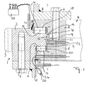
- the large rolling bearing 1 shown in FIG. 1 is typically used in a crane, whose superstructure rotatably supports it to its undercarriage. It includes an outer bearing ring 2, which has an outer toothing 3, and a inner bearing ring 4, which is formed in two parts and an upper ring 5 and a lower ring 6 comprises.
- the outer bearing ring 2 is by means of a plurality of screws 7, over the Scope of the bearing ring are distributed, attached to the flange 8.
- the inner one Bearing ring 4 is in a corresponding manner by means of a plurality of screws 7 on Attached flange 8 of the inner bearing ring 4 bearing member, wherein the screws 7 at the same time the connection of upper ring 5 and lower ring. 6 but they do not have to.
- the screws 7 extend parallel to Rotary axis of the large rolling bearing 1.
- the outer bearing ring 2 has a radially inwardly projecting Paragraph 9, at its upper and lower sides in each case a radial tread 10, 11 and on the inner peripheral surface of a circumferential tread 12 is formed is.
- the paragraph 9 jumps in a total groove-shaped, in the circumferential direction encircling recess 13 which, in the inner bearing ring 4, more precisely in the outer peripheral surface, is formed.
- the recess 13 has their upper and lower flanks radial treads 14 and 15 and at their Reason a peripheral tread 16, each of the tread 10 and 11 and 12 am Paragraph 9.
- FIG. 1 shows, run between the treads 10th and 14 or 11 and 15 cylindrical rolling elements 17 and 18, which form a thrust bearing, and between the peripheral treads 12 and 16 also cylindrical rolling elements 19, which cause a radial support and form a radial bearing.
- the rolling elements can be held in position by a cage 20 in a conventional manner become.
- the bearing gap 21 between the two bearing rings 2 and 4 can be sealed by seals 22 to the outside, so that the storage room against external influences is protected.
- the monitoring device associated with the large rolling bearing 1 comprises in the drawn embodiment four each non-contact Wegmesssensoren S1, S2, S3 and S4.
- the two displacement sensors S1 and S2 are included arranged in the interior of the inner bearing ring 4 and each extending in radial Direction. The head of the sensors S1 and S2 jumps into the bearing gap 21 before or ends at this.
- the sensors S1 and S2 key peripheral surfaces of outer bearing ring 2 from which limit the bearing gap 21 partially.
- the Wegmesssensor S1 thereby scans a cylindrical peripheral surface 23 between the two rows of rolling elements 17 and 18 from.
- the second displacement sensor S2 In contrast, it scans an oblique peripheral surface of the outer bearing ring 2, the is slightly conical, as Figure 1 shows.
- the cone angle of the conical peripheral surface 24 is preferably less than 25 °.
- the two displacement sensors S1 and S2 radial offset between the can measure both bearing rings 2 and 4, from the difference of the signals of the two Distance measuring sensors S1 and S2 in addition to the radial movements between the both bearing rings 2 and 4, the occurring axial movement are determined, through the conical peripheral surface 24, whose inclination is known.
- the two Sensors S1 and S2 are connected to the evaluation unit 25, which receives the signals on the one hand subtracted from each other, in addition to the radial movements and the To determine axial movements, and on the other hand with predetermined limits compares to determine and display wear. From the over the Sensors S1 and S2 specific radial and axial movements can tilt the game the two bearing rings 2 and 4 are determined to each other.
- Tilting play is a measure of the condition of the bearing.
- both show up Wear as well as deformation of the bearing rings as Kippspielveriere.
- To the others increase errors in the component, such as As cracks, the Kippspiel.
- the evaluation unit 25 compares this Tilting game with limits, which can be specified to the basis of this comparison To determine storage condition.
- the determination of the tilting game is also special here advantageous because an increased elongation of the screws in the axial direction increases the tilting play.
- the slewing bearings are designed differently can.
- the axial support and the radial support be effected by the same rolling elements, especially when the slewing bearings 1 is designed as a ball bearing.
- the slewing bearings 1 be designed as a double-row ball bearing. These are on the one hand in the outer Bearing ring 2 and on the other hand in the inner bearing ring 4, two in cross section formed approximately semicircular running surfaces (see Figure 3), which together the Form running surfaces for the trained as balls rolling elements 27.
- the order the sensors S1 to S4 substantially corresponds to those described above.
- the slewing bearings 1 may also be formed single row.
- the large roller bearing is a single-row ball bearing educated.
- the arrangement of the sensors S1 to S4 substantially corresponds the previously described.
Landscapes
- Engineering & Computer Science (AREA)
- General Engineering & Computer Science (AREA)
- Mechanical Engineering (AREA)
- Physics & Mathematics (AREA)
- General Physics & Mathematics (AREA)
- Rolling Contact Bearings (AREA)
Applications Claiming Priority (2)
| Application Number | Priority Date | Filing Date | Title |
|---|---|---|---|
| DE20316544U DE20316544U1 (de) | 2003-10-28 | 2003-10-28 | Überwachungsvorrichtung zur Überwachung von Großwälzlagern |
| DE20316544U | 2003-10-28 |
Publications (3)
| Publication Number | Publication Date |
|---|---|
| EP1528356A2 true EP1528356A2 (fr) | 2005-05-04 |
| EP1528356A3 EP1528356A3 (fr) | 2006-03-01 |
| EP1528356B1 EP1528356B1 (fr) | 2015-01-28 |
Family
ID=34306478
Family Applications (1)
| Application Number | Title | Priority Date | Filing Date |
|---|---|---|---|
| EP04025540.8A Expired - Lifetime EP1528356B1 (fr) | 2003-10-28 | 2004-10-27 | Dispositif pour la surveillance de grands paliers à roulement |
Country Status (2)
| Country | Link |
|---|---|
| EP (1) | EP1528356B1 (fr) |
| DE (1) | DE20316544U1 (fr) |
Cited By (24)
| Publication number | Priority date | Publication date | Assignee | Title |
|---|---|---|---|---|
| CN102072259A (zh) * | 2011-01-24 | 2011-05-25 | 南京工大数控科技有限公司 | 一种内植传感器的智能回转支承 |
| EP2290235A3 (fr) * | 2009-08-28 | 2012-01-11 | PRÜFTECHNIK Dieter Busch AG | Dispositif et procédé de détection du chargement de pales de rotor pivotantes |
| EP2532904A3 (fr) * | 2005-05-31 | 2012-12-19 | Mitsubishi Heavy Industries | Roulement annulaire pivotant |
| DE102012024269A1 (de) * | 2012-12-12 | 2014-06-12 | Imo Holding Gmbh | Momentenlager mit Abstandssensorik |
| CN106979755A (zh) * | 2017-03-31 | 2017-07-25 | 武汉理工大学 | 汽车水泵轴承轴向游隙自动测量仪 |
| WO2018041702A1 (fr) * | 2016-08-30 | 2018-03-08 | Thyssenkrupp Rothe Erde Gmbh | Palier et procédé de surveillance d'usure et/ou de mesure de charge |
| CN109470192A (zh) * | 2018-12-18 | 2019-03-15 | 南京磁谷科技有限公司 | 一种电磁轴承轴向传感器的安装结构 |
| CN109915492A (zh) * | 2019-04-23 | 2019-06-21 | 中铁工程服务有限公司 | 一种盾构机主轴承监测装置 |
| EP3483581B1 (fr) | 2017-11-08 | 2020-02-26 | Eolotec GmbH | Methode et dispositif permettant de surveiller le jeu de palier de roulements a rouleaux |
| US10975908B1 (en) | 2019-10-29 | 2021-04-13 | Schaeffler Monitoring Services Gmbh | Method and device for monitoring a bearing clearance of roller bearings |
| CN112709756A (zh) * | 2019-10-24 | 2021-04-27 | 斯凯孚公司 | 带有超声波距离传感器的滚动轴承 |
| CN112833091A (zh) * | 2019-11-25 | 2021-05-25 | 斯凯孚公司 | 具有滑动目标和相关联的传感器的轴承 |
| CN112833092A (zh) * | 2019-11-25 | 2021-05-25 | 斯凯孚公司 | 具有距离测量系统和相关联的槽的轴承 |
| CN112901652A (zh) * | 2019-11-19 | 2021-06-04 | 斯凯孚公司 | 具有距离传感器和锥形槽的轴承 |
| DE102020206785A1 (de) | 2020-05-29 | 2021-12-02 | Thyssenkrupp Ag | Wälzlager mit einem Sensor und Montagewerkzeug |
| CN113776827A (zh) * | 2020-05-20 | 2021-12-10 | 斯凯孚公司 | 涡流探头 |
| CN114033794A (zh) * | 2021-11-16 | 2022-02-11 | 武汉理工大学 | 一种回转支承运行状态在线监测装置 |
| US20220128096A1 (en) * | 2020-10-26 | 2022-04-28 | Aktiebolaget Skf | Rolling bearing assembly |
| CN114902019A (zh) * | 2020-01-03 | 2022-08-12 | 蒂森克虏伯罗特艾德德国有限公司 | 具有定位装置的滚动轴承 |
| CN115315581A (zh) * | 2020-02-11 | 2022-11-08 | 利勃海尔比伯拉赫零部件有限公司 | 具有监测装置的滚动轴承 |
| CN115681347A (zh) * | 2022-03-24 | 2023-02-03 | 于丽云 | 一种回转轴承磨损监测装置 |
| WO2023131540A1 (fr) * | 2022-01-10 | 2023-07-13 | Aktiebolaget Skf | Ensemble palier à roulement |
| WO2025012314A1 (fr) * | 2023-07-11 | 2025-01-16 | Liebherr-Components Biberach Gmbh | Grand roulement à rouleaux et procédé et dispositif de surveillance d'un tel grand roulement à rouleaux |
| WO2026041203A1 (fr) * | 2024-08-23 | 2026-02-26 | Vestas Wind Systems A/S | Procédé d'inspection d'une éolienne |
Families Citing this family (18)
| Publication number | Priority date | Publication date | Assignee | Title |
|---|---|---|---|---|
| DE102004052598A1 (de) * | 2004-10-29 | 2006-05-04 | Aktiebolaget Skf | Windenergieanlage |
| CN101410616A (zh) * | 2006-04-02 | 2009-04-15 | 维斯塔斯风力系统有限公司 | 用于风轮机的俯仰轴承,风轮机以及维护轴承的方法 |
| DE202007002609U1 (de) * | 2007-02-19 | 2008-04-03 | Landwehr, Markus | Drehverbindung |
| DE102007013160B4 (de) | 2007-03-20 | 2008-12-04 | ThyssenKrupp Fördertechnik GmbH | Verfahren und Einrichtung zur Kontrolle der Laufbahnen von Großwälzlagern |
| DE102007032972B4 (de) * | 2007-07-16 | 2015-08-06 | Knorr-Bremse Systeme für Nutzfahrzeuge GmbH | Messvorrichtung und Verfahren zur Erfassung einer axialen Verschiebung einer Welle |
| DE102008008727A1 (de) | 2008-02-12 | 2009-08-13 | Schaeffler Kg | Lager mit Positionsgeber |
| DE102008026081A1 (de) | 2008-05-30 | 2009-12-31 | Schaeffler Kg | Lagervorrichtung mit Positionsgeber |
| US8002472B2 (en) * | 2008-06-30 | 2011-08-23 | Nucor Corporation | Slew bearing system |
| DE102008046357A1 (de) * | 2008-09-09 | 2010-03-11 | Schaeffler Kg | Sensoranordnung zur Bestimmung einer Kenngröße für den Verschleiß eines Wälzlagers und Windkraftanlage |
| DE102012211566A1 (de) | 2012-07-03 | 2014-01-09 | Wobben Properties Gmbh | Überwachte Bauteilverbindung, Windenergieanlage, Verfahren zur Überwachung einer Bauteilverbindung auf ein ungewolltes Lösen der Bauteilverbindung im verbundenen Zustand |
| EP2743522A1 (fr) * | 2012-12-12 | 2014-06-18 | IMO Holding GmbH | Palier à moment ou roulement (de grande dimension) ou liaison rotative avec capteur(s) de rapprochement |
| DE112013007193A5 (de) | 2013-06-25 | 2016-03-03 | Imo Holding Gmbh | Federdrucksystem für Lageranordnung und damit ausgestattete Lageranordnung |
| DE102013010500B4 (de) | 2013-06-25 | 2018-12-27 | Imo Holding Gmbh | Mit Federdrucksystem ausgestattete Lageranordnung |
| DE102018200573A1 (de) * | 2018-01-15 | 2019-07-18 | Zf Friedrichshafen Ag | Schwenkantrieb mit Zustandsüberwachung |
| DE102019217789A1 (de) * | 2019-11-19 | 2021-05-20 | Aktiebolaget Skf | Lager mit Abstandssensoren und konischen Nuten |
| DE102021100222A1 (de) | 2021-01-08 | 2022-07-14 | Schaeffler Technologies AG & Co. KG | Verfahren zur Herstellung von verschiedenen Varianten einer Baureihe von Rundachslagern |
| NL2032602B1 (en) | 2022-07-26 | 2024-02-05 | Itrec Bv | Slew bearing with load monitoring |
| WO2026041202A1 (fr) * | 2024-08-23 | 2026-02-26 | Vestas Wind Systems A/S | Éolienne |
Citations (4)
| Publication number | Priority date | Publication date | Assignee | Title |
|---|---|---|---|---|
| US5336996A (en) | 1992-08-21 | 1994-08-09 | The Duriron Company, Inc. | Hall effect monitoring of wear of bearing supporting a rotor within a stationary housing |
| DE19755000C1 (de) | 1997-12-11 | 1999-03-04 | Krupp Ag Hoesch Krupp | Verschleißmessvorrichtung für Großwälzlager |
| US5955880A (en) | 1996-12-05 | 1999-09-21 | Beam; Palmer H. | Sealless pump rotor position and bearing monitor |
| DE10107067A1 (de) | 2000-02-14 | 2001-08-16 | Teikoku Denki Seisakusho Hyogo | Axiallagerverschleißanzeigevorrichtung für einen Motor, insbesondere einen gekapselten Motor |
Family Cites Families (4)
| Publication number | Priority date | Publication date | Assignee | Title |
|---|---|---|---|---|
| NL8503517A (nl) * | 1985-12-19 | 1987-07-16 | Skf Ind Trading & Dev | Zwenkring. |
| FR2680874B1 (fr) * | 1991-08-26 | 1995-03-24 | Roulements Soc Nouvelle | Circuits magnetiques. |
| DE4128807A1 (de) * | 1991-08-30 | 1993-03-04 | Hoesch Ag | Vorrichtung zum ueberwachen von waelzlagern |
| DE19919007B4 (de) * | 1999-04-27 | 2005-03-24 | Fag Kugelfischer Ag | Einrichtung zum Messen von Lagerdaten |
-
2003
- 2003-10-28 DE DE20316544U patent/DE20316544U1/de not_active Expired - Lifetime
-
2004
- 2004-10-27 EP EP04025540.8A patent/EP1528356B1/fr not_active Expired - Lifetime
Patent Citations (4)
| Publication number | Priority date | Publication date | Assignee | Title |
|---|---|---|---|---|
| US5336996A (en) | 1992-08-21 | 1994-08-09 | The Duriron Company, Inc. | Hall effect monitoring of wear of bearing supporting a rotor within a stationary housing |
| US5955880A (en) | 1996-12-05 | 1999-09-21 | Beam; Palmer H. | Sealless pump rotor position and bearing monitor |
| DE19755000C1 (de) | 1997-12-11 | 1999-03-04 | Krupp Ag Hoesch Krupp | Verschleißmessvorrichtung für Großwälzlager |
| DE10107067A1 (de) | 2000-02-14 | 2001-08-16 | Teikoku Denki Seisakusho Hyogo | Axiallagerverschleißanzeigevorrichtung für einen Motor, insbesondere einen gekapselten Motor |
Non-Patent Citations (1)
| Title |
|---|
| KRUPP: "Technische Mitteilungen", April 1993 |
Cited By (40)
| Publication number | Priority date | Publication date | Assignee | Title |
|---|---|---|---|---|
| EP2532904A3 (fr) * | 2005-05-31 | 2012-12-19 | Mitsubishi Heavy Industries | Roulement annulaire pivotant |
| EP2290235A3 (fr) * | 2009-08-28 | 2012-01-11 | PRÜFTECHNIK Dieter Busch AG | Dispositif et procédé de détection du chargement de pales de rotor pivotantes |
| CN102072259A (zh) * | 2011-01-24 | 2011-05-25 | 南京工大数控科技有限公司 | 一种内植传感器的智能回转支承 |
| DE102012024269A1 (de) * | 2012-12-12 | 2014-06-12 | Imo Holding Gmbh | Momentenlager mit Abstandssensorik |
| US20190195278A1 (en) * | 2016-08-30 | 2019-06-27 | Thyssenkrupp Rothe Erde Gmbh | Bearing and method for monitoring wear and/or measuring a load |
| WO2018041702A1 (fr) * | 2016-08-30 | 2018-03-08 | Thyssenkrupp Rothe Erde Gmbh | Palier et procédé de surveillance d'usure et/ou de mesure de charge |
| CN109690097A (zh) * | 2016-08-30 | 2019-04-26 | 蒂森克虏伯罗特艾德有限公司 | 轴承和用于监测磨损和/或测量载荷的方法 |
| US10738826B2 (en) | 2016-08-30 | 2020-08-11 | Thyssenkrupp Rothe Erde Gmbh | Bearing and method for monitoring wear and/or measuring a load |
| CN109690097B (zh) * | 2016-08-30 | 2020-12-11 | 蒂森克虏伯罗特艾德有限公司 | 轴承和用于监测磨损和/或测量载荷的方法 |
| CN106979755A (zh) * | 2017-03-31 | 2017-07-25 | 武汉理工大学 | 汽车水泵轴承轴向游隙自动测量仪 |
| EP3483581B1 (fr) | 2017-11-08 | 2020-02-26 | Eolotec GmbH | Methode et dispositif permettant de surveiller le jeu de palier de roulements a rouleaux |
| CN109470192A (zh) * | 2018-12-18 | 2019-03-15 | 南京磁谷科技有限公司 | 一种电磁轴承轴向传感器的安装结构 |
| CN109915492A (zh) * | 2019-04-23 | 2019-06-21 | 中铁工程服务有限公司 | 一种盾构机主轴承监测装置 |
| CN112709756A (zh) * | 2019-10-24 | 2021-04-27 | 斯凯孚公司 | 带有超声波距离传感器的滚动轴承 |
| US10975908B1 (en) | 2019-10-29 | 2021-04-13 | Schaeffler Monitoring Services Gmbh | Method and device for monitoring a bearing clearance of roller bearings |
| CN112901652A (zh) * | 2019-11-19 | 2021-06-04 | 斯凯孚公司 | 具有距离传感器和锥形槽的轴承 |
| CN112901652B (zh) * | 2019-11-19 | 2025-03-04 | 斯凯孚公司 | 具有距离传感器和锥形槽的轴承 |
| CN112833091A (zh) * | 2019-11-25 | 2021-05-25 | 斯凯孚公司 | 具有滑动目标和相关联的传感器的轴承 |
| CN112833092A (zh) * | 2019-11-25 | 2021-05-25 | 斯凯孚公司 | 具有距离测量系统和相关联的槽的轴承 |
| US12332272B2 (en) | 2020-01-03 | 2025-06-17 | thyssenkrupp rothe erde Germany GmbH | Rolling bearing having position-determining device |
| CN114902019A (zh) * | 2020-01-03 | 2022-08-12 | 蒂森克虏伯罗特艾德德国有限公司 | 具有定位装置的滚动轴承 |
| CN114902019B (zh) * | 2020-01-03 | 2024-03-08 | 蒂森克虏伯罗特艾德德国有限公司 | 具有定位装置的滚动轴承 |
| US12071984B2 (en) * | 2020-02-11 | 2024-08-27 | Liebherr-Components Biberach Gmbh | Rolling bearing with monitoring device |
| CN115315581A (zh) * | 2020-02-11 | 2022-11-08 | 利勃海尔比伯拉赫零部件有限公司 | 具有监测装置的滚动轴承 |
| US20220364605A1 (en) * | 2020-02-11 | 2022-11-17 | Oliver Born | Rolling bearing with monitoring device |
| CN113776827A (zh) * | 2020-05-20 | 2021-12-10 | 斯凯孚公司 | 涡流探头 |
| DE102020206785A1 (de) | 2020-05-29 | 2021-12-02 | Thyssenkrupp Ag | Wälzlager mit einem Sensor und Montagewerkzeug |
| DE102020206785B4 (de) * | 2020-05-29 | 2024-02-15 | Thyssenkrupp Ag | Wälzlager mit einem Sensor und Montagewerkzeug |
| AT524361B1 (de) * | 2020-10-26 | 2023-07-15 | Skf Ab | Wälzlageranordnung |
| US11624407B2 (en) * | 2020-10-26 | 2023-04-11 | Aktiebolaget Skf | Rolling bearing assembly |
| AT524361A3 (de) * | 2020-10-26 | 2022-07-15 | Skf Ab | Wälzlageranordnung |
| US20220128096A1 (en) * | 2020-10-26 | 2022-04-28 | Aktiebolaget Skf | Rolling bearing assembly |
| CN114033794B (zh) * | 2021-11-16 | 2022-11-15 | 武汉理工大学 | 一种回转支承运行状态在线监测装置 |
| CN114033794A (zh) * | 2021-11-16 | 2022-02-11 | 武汉理工大学 | 一种回转支承运行状态在线监测装置 |
| WO2023131540A1 (fr) * | 2022-01-10 | 2023-07-13 | Aktiebolaget Skf | Ensemble palier à roulement |
| AT526890A5 (de) * | 2022-01-10 | 2025-03-15 | Skf Ab | Wälzlageranordnung |
| AT526890B1 (de) * | 2022-01-10 | 2025-10-15 | Skf Ab | Wälzlageranordnung |
| CN115681347A (zh) * | 2022-03-24 | 2023-02-03 | 于丽云 | 一种回转轴承磨损监测装置 |
| WO2025012314A1 (fr) * | 2023-07-11 | 2025-01-16 | Liebherr-Components Biberach Gmbh | Grand roulement à rouleaux et procédé et dispositif de surveillance d'un tel grand roulement à rouleaux |
| WO2026041203A1 (fr) * | 2024-08-23 | 2026-02-26 | Vestas Wind Systems A/S | Procédé d'inspection d'une éolienne |
Also Published As
| Publication number | Publication date |
|---|---|
| EP1528356A3 (fr) | 2006-03-01 |
| EP1528356B1 (fr) | 2015-01-28 |
| DE20316544U1 (de) | 2005-03-10 |
Similar Documents
| Publication | Publication Date | Title |
|---|---|---|
| EP1528356B1 (fr) | Dispositif pour la surveillance de grands paliers à roulement | |
| EP3507513B1 (fr) | Palier et methode de surveillance d'usure et/ou de mesure de charge | |
| EP0413119B1 (fr) | Grand palier à roulement à centre ouvert | |
| EP4081719B1 (fr) | Palier à roulement doté d'un dispositif de surveillance | |
| DE102017207814A1 (de) | Schwenklager mit Dichtungsanordnung | |
| DE2947937C2 (de) | Verfahren und Vorrichtung zur Bestimmung von Wälzlagerschäden | |
| DE102019217789A1 (de) | Lager mit Abstandssensoren und konischen Nuten | |
| DE102019218884B4 (de) | Großwälzlager und Verfahren zur Verschleißmessung | |
| DE102019216610A1 (de) | Lager mit optischem Sensor und zugehöriger Nut | |
| DE102019218143A1 (de) | Lager mit einem gleitendem Zielobjekt und zugehörigem Sensor | |
| WO2014090347A1 (fr) | Ensemble palier à roulement ou à couple doté d'un ensemble de capteurs | |
| DE102007013160B4 (de) | Verfahren und Einrichtung zur Kontrolle der Laufbahnen von Großwälzlagern | |
| DE2721281A1 (de) | Exzentrizitaetsmessvorrichtung | |
| EP2743522A1 (fr) | Palier à moment ou roulement (de grande dimension) ou liaison rotative avec capteur(s) de rapprochement | |
| DE102006028294A1 (de) | Radiallageranordnung mit einer diese zentrierenden Spannringanordnung | |
| AT524361B1 (de) | Wälzlageranordnung | |
| EP4500040A1 (fr) | Palier à roulement doté d'un ensemble capteur ultrasonore pour surveiller un endommagement de chemin de roulement | |
| DE19713688B4 (de) | Wälzlager mit einer Wegmeßeinrichtung | |
| DE102005042776A1 (de) | Sensoranordnung | |
| DE102019218144A1 (de) | Lager mit einem Abstandsmesssystem und zugehöriger Nut | |
| DE102022206188A1 (de) | System zum Bestimmen des Verschleißes eines Lagers und zugehöriges Verfahren | |
| EP3339853B1 (fr) | Procédé d'analyse acoustique de la trajectoire d'un gros palier à roulement | |
| DE102021211491A1 (de) | System zum Bestimmen zumindest eines Defekts eines Lagers und zugehöriges Verfahren | |
| AT526890B1 (de) | Wälzlageranordnung | |
| DE102010005476B4 (de) | Verfahren und Vorrichtung zur Erfassung der Last in einem Wälzlager |
Legal Events
| Date | Code | Title | Description |
|---|---|---|---|
| PUAI | Public reference made under article 153(3) epc to a published international application that has entered the european phase |
Free format text: ORIGINAL CODE: 0009012 |
|
| AK | Designated contracting states |
Kind code of ref document: A2 Designated state(s): AT BE BG CH CY CZ DE DK EE ES FI FR GB GR HU IE IT LI LU MC NL PL PT RO SE SI SK TR |
|
| AX | Request for extension of the european patent |
Extension state: AL HR LT LV MK |
|
| PUAL | Search report despatched |
Free format text: ORIGINAL CODE: 0009013 |
|
| AK | Designated contracting states |
Kind code of ref document: A3 Designated state(s): AT BE BG CH CY CZ DE DK EE ES FI FR GB GR HU IE IT LI LU MC NL PL PT RO SE SI SK TR |
|
| AX | Request for extension of the european patent |
Extension state: AL HR LT LV MK |
|
| RIC1 | Information provided on ipc code assigned before grant |
Ipc: F16C 19/52 20060101ALI20060111BHEP Ipc: G01B 21/16 20060101AFI20050120BHEP Ipc: G01B 11/14 20060101ALI20060111BHEP Ipc: G01M 13/04 20060101ALI20060111BHEP Ipc: G01B 7/14 20060101ALI20060111BHEP |
|
| 17P | Request for examination filed |
Effective date: 20060725 |
|
| AKX | Designation fees paid |
Designated state(s): AT BE BG CH CY CZ DE DK EE ES FI FR GB GR HU IE IT LI LU MC NL PL PT RO SE SI SK TR |
|
| RAP1 | Party data changed (applicant data changed or rights of an application transferred) |
Owner name: LIEBHERR-COMPONENTS BIBERACH GMBH |
|
| 17Q | First examination report despatched |
Effective date: 20120928 |
|
| GRAP | Despatch of communication of intention to grant a patent |
Free format text: ORIGINAL CODE: EPIDOSNIGR1 |
|
| INTG | Intention to grant announced |
Effective date: 20140916 |
|
| GRAS | Grant fee paid |
Free format text: ORIGINAL CODE: EPIDOSNIGR3 |
|
| GRAA | (expected) grant |
Free format text: ORIGINAL CODE: 0009210 |
|
| AK | Designated contracting states |
Kind code of ref document: B1 Designated state(s): AT BE BG CH CY CZ DE DK EE ES FI FR GB GR HU IE IT LI LU MC NL PL PT RO SE SI SK TR |
|
| REG | Reference to a national code |
Ref country code: GB Ref legal event code: FG4D Free format text: NOT ENGLISH |
|
| REG | Reference to a national code |
Ref country code: CH Ref legal event code: EP |
|
| REG | Reference to a national code |
Ref country code: IE Ref legal event code: FG4D Free format text: LANGUAGE OF EP DOCUMENT: GERMAN |
|
| REG | Reference to a national code |
Ref country code: DE Ref legal event code: R096 Ref document number: 502004014818 Country of ref document: DE Effective date: 20150305 |
|
| REG | Reference to a national code |
Ref country code: AT Ref legal event code: REF Ref document number: 708419 Country of ref document: AT Kind code of ref document: T Effective date: 20150315 |
|
| REG | Reference to a national code |
Ref country code: NL Ref legal event code: T3 |
|
| PG25 | Lapsed in a contracting state [announced via postgrant information from national office to epo] |
Ref country code: FI Free format text: LAPSE BECAUSE OF FAILURE TO SUBMIT A TRANSLATION OF THE DESCRIPTION OR TO PAY THE FEE WITHIN THE PRESCRIBED TIME-LIMIT Effective date: 20150128 Ref country code: BG Free format text: LAPSE BECAUSE OF FAILURE TO SUBMIT A TRANSLATION OF THE DESCRIPTION OR TO PAY THE FEE WITHIN THE PRESCRIBED TIME-LIMIT Effective date: 20150428 Ref country code: SE Free format text: LAPSE BECAUSE OF FAILURE TO SUBMIT A TRANSLATION OF THE DESCRIPTION OR TO PAY THE FEE WITHIN THE PRESCRIBED TIME-LIMIT Effective date: 20150128 Ref country code: ES Free format text: LAPSE BECAUSE OF FAILURE TO SUBMIT A TRANSLATION OF THE DESCRIPTION OR TO PAY THE FEE WITHIN THE PRESCRIBED TIME-LIMIT Effective date: 20150128 |
|
| PG25 | Lapsed in a contracting state [announced via postgrant information from national office to epo] |
Ref country code: PL Free format text: LAPSE BECAUSE OF FAILURE TO SUBMIT A TRANSLATION OF THE DESCRIPTION OR TO PAY THE FEE WITHIN THE PRESCRIBED TIME-LIMIT Effective date: 20150128 Ref country code: GR Free format text: LAPSE BECAUSE OF FAILURE TO SUBMIT A TRANSLATION OF THE DESCRIPTION OR TO PAY THE FEE WITHIN THE PRESCRIBED TIME-LIMIT Effective date: 20150429 |
|
| REG | Reference to a national code |
Ref country code: FR Ref legal event code: PLFP Year of fee payment: 12 |
|
| REG | Reference to a national code |
Ref country code: DE Ref legal event code: R097 Ref document number: 502004014818 Country of ref document: DE |
|
| PG25 | Lapsed in a contracting state [announced via postgrant information from national office to epo] |
Ref country code: RO Free format text: LAPSE BECAUSE OF FAILURE TO SUBMIT A TRANSLATION OF THE DESCRIPTION OR TO PAY THE FEE WITHIN THE PRESCRIBED TIME-LIMIT Effective date: 20150128 Ref country code: CZ Free format text: LAPSE BECAUSE OF FAILURE TO SUBMIT A TRANSLATION OF THE DESCRIPTION OR TO PAY THE FEE WITHIN THE PRESCRIBED TIME-LIMIT Effective date: 20150128 Ref country code: EE Free format text: LAPSE BECAUSE OF FAILURE TO SUBMIT A TRANSLATION OF THE DESCRIPTION OR TO PAY THE FEE WITHIN THE PRESCRIBED TIME-LIMIT Effective date: 20150128 Ref country code: SK Free format text: LAPSE BECAUSE OF FAILURE TO SUBMIT A TRANSLATION OF THE DESCRIPTION OR TO PAY THE FEE WITHIN THE PRESCRIBED TIME-LIMIT Effective date: 20150128 Ref country code: DK Free format text: LAPSE BECAUSE OF FAILURE TO SUBMIT A TRANSLATION OF THE DESCRIPTION OR TO PAY THE FEE WITHIN THE PRESCRIBED TIME-LIMIT Effective date: 20150128 |
|
| PLBE | No opposition filed within time limit |
Free format text: ORIGINAL CODE: 0009261 |
|
| STAA | Information on the status of an ep patent application or granted ep patent |
Free format text: STATUS: NO OPPOSITION FILED WITHIN TIME LIMIT |
|
| PG25 | Lapsed in a contracting state [announced via postgrant information from national office to epo] |
Ref country code: IT Free format text: LAPSE BECAUSE OF FAILURE TO SUBMIT A TRANSLATION OF THE DESCRIPTION OR TO PAY THE FEE WITHIN THE PRESCRIBED TIME-LIMIT Effective date: 20150128 |
|
| 26N | No opposition filed |
Effective date: 20151029 |
|
| PG25 | Lapsed in a contracting state [announced via postgrant information from national office to epo] |
Ref country code: SI Free format text: LAPSE BECAUSE OF FAILURE TO SUBMIT A TRANSLATION OF THE DESCRIPTION OR TO PAY THE FEE WITHIN THE PRESCRIBED TIME-LIMIT Effective date: 20150128 |
|
| PG25 | Lapsed in a contracting state [announced via postgrant information from national office to epo] |
Ref country code: LU Free format text: LAPSE BECAUSE OF FAILURE TO SUBMIT A TRANSLATION OF THE DESCRIPTION OR TO PAY THE FEE WITHIN THE PRESCRIBED TIME-LIMIT Effective date: 20151027 |
|
| REG | Reference to a national code |
Ref country code: CH Ref legal event code: PL |
|
| PG25 | Lapsed in a contracting state [announced via postgrant information from national office to epo] |
Ref country code: MC Free format text: LAPSE BECAUSE OF FAILURE TO SUBMIT A TRANSLATION OF THE DESCRIPTION OR TO PAY THE FEE WITHIN THE PRESCRIBED TIME-LIMIT Effective date: 20150128 |
|
| REG | Reference to a national code |
Ref country code: IE Ref legal event code: MM4A |
|
| PG25 | Lapsed in a contracting state [announced via postgrant information from national office to epo] |
Ref country code: CH Free format text: LAPSE BECAUSE OF NON-PAYMENT OF DUE FEES Effective date: 20151031 Ref country code: LI Free format text: LAPSE BECAUSE OF NON-PAYMENT OF DUE FEES Effective date: 20151031 |
|
| REG | Reference to a national code |
Ref country code: FR Ref legal event code: PLFP Year of fee payment: 13 |
|
| PG25 | Lapsed in a contracting state [announced via postgrant information from national office to epo] |
Ref country code: IE Free format text: LAPSE BECAUSE OF NON-PAYMENT OF DUE FEES Effective date: 20151027 |
|
| REG | Reference to a national code |
Ref country code: AT Ref legal event code: MM01 Ref document number: 708419 Country of ref document: AT Kind code of ref document: T Effective date: 20151027 |
|
| PG25 | Lapsed in a contracting state [announced via postgrant information from national office to epo] |
Ref country code: AT Free format text: LAPSE BECAUSE OF NON-PAYMENT OF DUE FEES Effective date: 20151027 |
|
| PG25 | Lapsed in a contracting state [announced via postgrant information from national office to epo] |
Ref country code: HU Free format text: LAPSE BECAUSE OF FAILURE TO SUBMIT A TRANSLATION OF THE DESCRIPTION OR TO PAY THE FEE WITHIN THE PRESCRIBED TIME-LIMIT; INVALID AB INITIO Effective date: 20041027 |
|
| PG25 | Lapsed in a contracting state [announced via postgrant information from national office to epo] |
Ref country code: CY Free format text: LAPSE BECAUSE OF FAILURE TO SUBMIT A TRANSLATION OF THE DESCRIPTION OR TO PAY THE FEE WITHIN THE PRESCRIBED TIME-LIMIT Effective date: 20150128 |
|
| PG25 | Lapsed in a contracting state [announced via postgrant information from national office to epo] |
Ref country code: TR Free format text: LAPSE BECAUSE OF FAILURE TO SUBMIT A TRANSLATION OF THE DESCRIPTION OR TO PAY THE FEE WITHIN THE PRESCRIBED TIME-LIMIT Effective date: 20150128 |
|
| REG | Reference to a national code |
Ref country code: FR Ref legal event code: PLFP Year of fee payment: 14 |
|
| PG25 | Lapsed in a contracting state [announced via postgrant information from national office to epo] |
Ref country code: PT Free format text: LAPSE BECAUSE OF FAILURE TO SUBMIT A TRANSLATION OF THE DESCRIPTION OR TO PAY THE FEE WITHIN THE PRESCRIBED TIME-LIMIT Effective date: 20150128 |
|
| REG | Reference to a national code |
Ref country code: FR Ref legal event code: PLFP Year of fee payment: 15 |
|
| PGFP | Annual fee paid to national office [announced via postgrant information from national office to epo] |
Ref country code: NL Payment date: 20231023 Year of fee payment: 20 |
|
| PGFP | Annual fee paid to national office [announced via postgrant information from national office to epo] |
Ref country code: GB Payment date: 20231023 Year of fee payment: 20 |
|
| PGFP | Annual fee paid to national office [announced via postgrant information from national office to epo] |
Ref country code: FR Payment date: 20231024 Year of fee payment: 20 Ref country code: DE Payment date: 20231030 Year of fee payment: 20 |
|
| PGFP | Annual fee paid to national office [announced via postgrant information from national office to epo] |
Ref country code: BE Payment date: 20231023 Year of fee payment: 20 |
|
| REG | Reference to a national code |
Ref country code: DE Ref legal event code: R071 Ref document number: 502004014818 Country of ref document: DE |
|
| REG | Reference to a national code |
Ref country code: NL Ref legal event code: MK Effective date: 20241026 |
|
| REG | Reference to a national code |
Ref country code: GB Ref legal event code: PE20 Expiry date: 20241026 |
|
| REG | Reference to a national code |
Ref country code: BE Ref legal event code: MK Effective date: 20241027 |
|
| PG25 | Lapsed in a contracting state [announced via postgrant information from national office to epo] |
Ref country code: GB Free format text: LAPSE BECAUSE OF EXPIRATION OF PROTECTION Effective date: 20241026 |
|
| PG25 | Lapsed in a contracting state [announced via postgrant information from national office to epo] |
Ref country code: GB Free format text: LAPSE BECAUSE OF EXPIRATION OF PROTECTION Effective date: 20241026 |