EP1528406A1 - Radarsystem mit RQS Korrektur - Google Patents
Radarsystem mit RQS Korrektur Download PDFInfo
- Publication number
- EP1528406A1 EP1528406A1 EP04025842A EP04025842A EP1528406A1 EP 1528406 A1 EP1528406 A1 EP 1528406A1 EP 04025842 A EP04025842 A EP 04025842A EP 04025842 A EP04025842 A EP 04025842A EP 1528406 A1 EP1528406 A1 EP 1528406A1
- Authority
- EP
- European Patent Office
- Prior art keywords
- target
- harmonics
- radar system
- detected
- unit
- Prior art date
- Legal status (The legal status is an assumption and is not a legal conclusion. Google has not performed a legal analysis and makes no representation as to the accuracy of the status listed.)
- Withdrawn
Links
- 238000012937 correction Methods 0.000 title claims abstract description 18
- 238000001228 spectrum Methods 0.000 claims abstract description 7
- 238000012545 processing Methods 0.000 claims description 34
- 238000000034 method Methods 0.000 claims description 16
- 238000004891 communication Methods 0.000 claims description 13
- 230000005540 biological transmission Effects 0.000 claims description 9
- 230000008569 process Effects 0.000 claims description 7
- 238000001514 detection method Methods 0.000 claims description 6
- 238000003672 processing method Methods 0.000 claims description 2
- 230000003321 amplification Effects 0.000 abstract description 4
- 238000003199 nucleic acid amplification method Methods 0.000 abstract description 4
- 238000010276 construction Methods 0.000 description 11
- 238000010586 diagram Methods 0.000 description 10
- 238000005070 sampling Methods 0.000 description 4
- 230000008859 change Effects 0.000 description 3
- 230000007423 decrease Effects 0.000 description 3
- 230000000694 effects Effects 0.000 description 3
- 230000006866 deterioration Effects 0.000 description 2
- 238000005259 measurement Methods 0.000 description 2
- 238000012986 modification Methods 0.000 description 2
- 230000004048 modification Effects 0.000 description 2
- 238000012544 monitoring process Methods 0.000 description 2
- 230000005856 abnormality Effects 0.000 description 1
- 230000003044 adaptive effect Effects 0.000 description 1
- 238000006243 chemical reaction Methods 0.000 description 1
- 238000007796 conventional method Methods 0.000 description 1
Images




Classifications
-
- G—PHYSICS
- G01—MEASURING; TESTING
- G01S—RADIO DIRECTION-FINDING; RADIO NAVIGATION; DETERMINING DISTANCE OR VELOCITY BY USE OF RADIO WAVES; LOCATING OR PRESENCE-DETECTING BY USE OF THE REFLECTION OR RERADIATION OF RADIO WAVES; ANALOGOUS ARRANGEMENTS USING OTHER WAVES
- G01S7/00—Details of systems according to groups G01S13/00, G01S15/00, G01S17/00
- G01S7/02—Details of systems according to groups G01S13/00, G01S15/00, G01S17/00 of systems according to group G01S13/00
- G01S7/41—Details of systems according to groups G01S13/00, G01S15/00, G01S17/00 of systems according to group G01S13/00 using analysis of echo signal for target characterisation; Target signature; Target cross-section
- G01S7/411—Identification of targets based on measurements of radar reflectivity
-
- G—PHYSICS
- G01—MEASURING; TESTING
- G01S—RADIO DIRECTION-FINDING; RADIO NAVIGATION; DETERMINING DISTANCE OR VELOCITY BY USE OF RADIO WAVES; LOCATING OR PRESENCE-DETECTING BY USE OF THE REFLECTION OR RERADIATION OF RADIO WAVES; ANALOGOUS ARRANGEMENTS USING OTHER WAVES
- G01S13/00—Systems using the reflection or reradiation of radio waves, e.g. radar systems; Analogous systems using reflection or reradiation of waves whose nature or wavelength is irrelevant or unspecified
- G01S13/88—Radar or analogous systems specially adapted for specific applications
- G01S13/93—Radar or analogous systems specially adapted for specific applications for anti-collision purposes
- G01S13/931—Radar or analogous systems specially adapted for specific applications for anti-collision purposes of land vehicles
-
- G—PHYSICS
- G01—MEASURING; TESTING
- G01S—RADIO DIRECTION-FINDING; RADIO NAVIGATION; DETERMINING DISTANCE OR VELOCITY BY USE OF RADIO WAVES; LOCATING OR PRESENCE-DETECTING BY USE OF THE REFLECTION OR RERADIATION OF RADIO WAVES; ANALOGOUS ARRANGEMENTS USING OTHER WAVES
- G01S7/00—Details of systems according to groups G01S13/00, G01S15/00, G01S17/00
- G01S7/02—Details of systems according to groups G01S13/00, G01S15/00, G01S17/00 of systems according to group G01S13/00
- G01S7/35—Details of non-pulse systems
- G01S7/352—Receivers
- G01S7/354—Extracting wanted echo-signals
-
- G—PHYSICS
- G01—MEASURING; TESTING
- G01S—RADIO DIRECTION-FINDING; RADIO NAVIGATION; DETERMINING DISTANCE OR VELOCITY BY USE OF RADIO WAVES; LOCATING OR PRESENCE-DETECTING BY USE OF THE REFLECTION OR RERADIATION OF RADIO WAVES; ANALOGOUS ARRANGEMENTS USING OTHER WAVES
- G01S13/00—Systems using the reflection or reradiation of radio waves, e.g. radar systems; Analogous systems using reflection or reradiation of waves whose nature or wavelength is irrelevant or unspecified
- G01S13/88—Radar or analogous systems specially adapted for specific applications
- G01S13/93—Radar or analogous systems specially adapted for specific applications for anti-collision purposes
- G01S13/931—Radar or analogous systems specially adapted for specific applications for anti-collision purposes of land vehicles
- G01S2013/9321—Velocity regulation, e.g. cruise control
-
- G—PHYSICS
- G01—MEASURING; TESTING
- G01S—RADIO DIRECTION-FINDING; RADIO NAVIGATION; DETERMINING DISTANCE OR VELOCITY BY USE OF RADIO WAVES; LOCATING OR PRESENCE-DETECTING BY USE OF THE REFLECTION OR RERADIATION OF RADIO WAVES; ANALOGOUS ARRANGEMENTS USING OTHER WAVES
- G01S13/00—Systems using the reflection or reradiation of radio waves, e.g. radar systems; Analogous systems using reflection or reradiation of waves whose nature or wavelength is irrelevant or unspecified
- G01S13/88—Radar or analogous systems specially adapted for specific applications
- G01S13/93—Radar or analogous systems specially adapted for specific applications for anti-collision purposes
- G01S13/931—Radar or analogous systems specially adapted for specific applications for anti-collision purposes of land vehicles
- G01S2013/9327—Sensor installation details
- G01S2013/93271—Sensor installation details in the front of the vehicles
-
- G—PHYSICS
- G01—MEASURING; TESTING
- G01S—RADIO DIRECTION-FINDING; RADIO NAVIGATION; DETERMINING DISTANCE OR VELOCITY BY USE OF RADIO WAVES; LOCATING OR PRESENCE-DETECTING BY USE OF THE REFLECTION OR RERADIATION OF RADIO WAVES; ANALOGOUS ARRANGEMENTS USING OTHER WAVES
- G01S13/00—Systems using the reflection or reradiation of radio waves, e.g. radar systems; Analogous systems using reflection or reradiation of waves whose nature or wavelength is irrelevant or unspecified
- G01S13/88—Radar or analogous systems specially adapted for specific applications
- G01S13/93—Radar or analogous systems specially adapted for specific applications for anti-collision purposes
- G01S13/931—Radar or analogous systems specially adapted for specific applications for anti-collision purposes of land vehicles
- G01S2013/9327—Sensor installation details
- G01S2013/93275—Sensor installation details in the bumper area
-
- G—PHYSICS
- G01—MEASURING; TESTING
- G01S—RADIO DIRECTION-FINDING; RADIO NAVIGATION; DETERMINING DISTANCE OR VELOCITY BY USE OF RADIO WAVES; LOCATING OR PRESENCE-DETECTING BY USE OF THE REFLECTION OR RERADIATION OF RADIO WAVES; ANALOGOUS ARRANGEMENTS USING OTHER WAVES
- G01S7/00—Details of systems according to groups G01S13/00, G01S15/00, G01S17/00
- G01S7/02—Details of systems according to groups G01S13/00, G01S15/00, G01S17/00 of systems according to group G01S13/00
- G01S7/35—Details of non-pulse systems
- G01S7/352—Receivers
- G01S7/356—Receivers involving particularities of FFT processing
Definitions
- the invention relates to a radar system, a signal processing apparatus for the radar system, and a signal processing method for the radar system.
- RCS value is an index of easiness of reflection of a radio wave. It is generally known that the larger the RCS value is, the larger the target is, although it is influenced by a shape and a material. That is, the calculated RCS value is one of important indices to decide a degree of importance and a degree of danger of the target. Particularly, it is important information when the system is applied to pre-crash safety or the like using a vehicle-mounted radar system.
- JP-A-2-27283 there is disclosed a system in which an AGC (Auto Gain Controller) circuit is provided in an amplifier disposed between a receiving antenna and an A/D converter and when a large reception signal is inputted, an amplification gain is suppressed, thereby preventing an input signal from exceeding the dynamic (input voltage) range of the A/D converter.
- AGC Automatic Gain Controller
- An input of a reflection wave whose strength exceeds a dynamic (input voltage) range of an A/D converter of a radar system to the A/D converter is detected and input amplitude information is corrected in accordance with the strength.
- a radar system which can calculate an RCS at high precision can be provided.
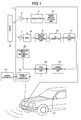
- the radar system 1 is often attached to a front side of a host vehicle 15. An outline of a measurement principle of the milli-meter wave radar will be explained.
- a modulation signal for switching the dual-tone is formed by a transmission control unit 3 and an electromagnetic wave of a milli-meter wave band formed by an oscillator 4 on the basis of the modulation signal is transmitted frontward of the host vehicle 15 from a transmitting antenna 5.
- a radio wave reflected from a front-running vehicle, an obstacle along a road, a pedestrian, or the like (hereinafter, referred to as a target 6) is received by a receiving antenna 7 and mixed with the transmission wave by a mixer 8, thereby frequency-converting it from the milli-meter wave frequency band into an IF (Intermediate Frequency band).
- a beat signal extracted by the mixer is amplified by an analog signal processing unit 9.
- the amplified beat signal is converted into a digital signal by an A/D converter 10 and FFT-processed by an FFT (Fast Fourier Transform) processing unit 11, so that a target peak is obtained.
- FFT Fast Fourier Transform
- the obtained target peak is signal-processed by a target processing unit 12 and a relative velocity, a distance, and an angle of direction (hereinafter, referred to as target information) are calculated.
- target information a relative velocity, a distance, and an angle of direction
- the RCS is calculated in an RCS calculation unit 18 by using the peak strength of the target peak, the distance to the target 6 calculated in the target processing unit 12, and a radar constant (A) recorded in a calibration data recording unit 25.
- a detailed calculating method of the RCS will be explained hereinafter.
- the calculated RCS and the target information are transmitted to an upper system 14 or the like such as ACC (Adaptive Cruise Control) unit, a collision warning system unit, and the like through a communication driver unit 13 and used for controlling the vehicle and controlling a warning to the operator.
- ACC Adaptive Cruise Control
- Fig. 2 shows a construction of the analog signal processing unit 9.
- the analog signal processing unit 9 is constructed by a preamplifier unit 16, a DC-servo unit 17, a demodulation unit 19, an S/H (Sample & Hold) unit 20, and a secondary amplifier unit 21.
- the beat signal inputted from the mixer 8 is amplified by the preamplifier unit 16.
- the DC-servo unit 17 functions to cancel a DC offset of the beat signal. Since beat signals (F1, F2) of different phases corresponding to two transmitting frequencies (CF1, CF2) which were modulated upon transmission have been superposed to the amplified signal, those signals are demodulated in the demodulation unit 19.
- the demodulated two kinds of beat signals are sampled and held in the S/H unit 20, again amplified in the secondary amplifier unit 21, and thereafter, outputted to the A/D converter 10.
- Figs. 3A to 3C are diagrams showing processes which are executed to the reception signal by the analog signal processing unit 9, A/D converter 10, and FFT processing unit 11.
- a beat signal 22 amplified in the secondary amplifier unit 21 of the analog signal processing unit 9 has a waveform as shown in Fig. 3A.
- the sampled signal 23 is FFT-processed by the FFT processing unit 11 by setting the number (N) of FFT samples to one frame, so that a frequency spectrum 24 of the beat signal 22 as shown in Fig. 3C in which an upper limit of the frequency is set to Fs/2 [Hz] is obtained.
- the input signal is assumed to be a sine wave of a frequency f1 for simplicity of explanation, even the input signal including a plurality of frequency components can be separated into frequency peaks so long as they are away by resolution Fs/2 ⁇ N [Hz] or more of the FFT from each other and the frequencies are smaller than Fs/2.
- Target peak strength S T after the FFT process is expressed by the following equation (2) by substituting a conversion gain (loss) G C in the mixer 8, a gain G A in the analog signal processing unit 9, and an FFT coefficient C F in the FFT processing unit 11 into the equation (1).
- S T Pt ⁇ Gt ⁇ Gr ⁇ Gc ⁇ G A ⁇ 2 ⁇ C F ⁇ (4 ⁇ ) 3
- R 4 A ⁇ R 4
- the RCS of the target 6 can be calculated by the equation (4) by using the target peak strength S T according to the actual target, the distance R to the target, and the radar constant (A) mentioned above.
- an FFT-processed frequency spectrum 29 becomes as shown in Fig. 4C.
- a target peak should appear inherently only in a position corresponding to the frequency f1
- a third harmonic 30 appears in a position corresponding to (3 ⁇ f1)
- a fifth harmonic 31 appears in a position corresponding to (5 ⁇ f1), ....
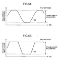
- the inherent target peak strength of fundamental wave S T is calculated to seem lower than inherent target peak strength 37. Since the target peak strength S T is obtained to be small, the RCS which is calculated by the equation (4) also decreases by such an amount and the target 6 is recognized to be a target whose reflection is smaller than the actual reflection. A change amount of the target peak strength S T at this time is proportional to the order of the harmonic which is detected. The changes in this case are shown in Figs. 5A and 5B.
- Fig. 5A shows an input signal waveform 32 in the case where the input signal strength is larger than the dynamic input voltage range by about 10%.
- Fig. 5B shows an input signal waveform 33 in the case where the input signal strength is larger than the dynamic (input voltage) range by about 100%.
- the waveform of Fig. 5B is closer to a rectangular wave than that of Fig. 5A and includes harmonic components of higher orders. Therefore, it will be understood that the higher the maximum order of the harmonic which is detected is, the larger the strength of the inherent input signal waveform is.
- a correction amount of the input amplitude can be uniquely determined by the order of the harmonic of the FFT waveform.
- Fig. 6 is a block diagram showing an embodiment of the radar system 1 using the invention.
- Fig. 6 differs from Fig. 1 in a point that the radar system of Fig. 6 has a harmonics detection unit 38 for searching for peaks corresponding to the frequencies of 3 times, 5 times, ... of the frequency of each peak with respect to all target peaks in the spectrum which was FFT-processed in the FFT processing unit 11.
- harmonics it is presumed that the beat signal has been clamped in the process in the A/D converter, the input signal has been lost, and an error has occurred in the digital signal which was inputted to the FFT processing unit 11 as described with reference to Figs. 4A to 4C, 5A, and 5B.
- the upper system such as an ACC control unit for controlling the vehicle by using the information measured by the radar system 1 can be notified that the information measured by the radar system 1 is unreliable. Therefore, the control can be stopped on the upper system side or the operator can be given a warning.
- the upper system 14 can detect the occurrence of abnormality in the radar system 1 and take a necessary measure such as stop of the control, provision of a warning, or the like.
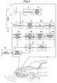
- Fig. 7 is a block diagram showing another embodiment of the radar system 1 using the invention.
- Fig. 7 differs from Fig. 1 in a point that the radar system there has a harmonic order measuring unit 34 for measuring the maximum order of the harmonics for the target peaks in the case where the harmonics detection unit 38 detects the harmonics for the target peaks and an input amplitude correction unit 36 for correcting amplitude information in accordance with the measured maximum order of the harmonics.
- the target processing unit 12 calculates the target information and the RCS calculation unit 18 calculates the RCS.
- the stop of the control and the provision of the warning to the. operator can be performed on the upper system side by using such a construction that the fact that the error is included in the information measured by the radar is transmitted to the upper system 14 or the like by using the communication driver unit 13, such a construction that the communication with the upper system by the communication driver unit 13 is stopped, or such a construction that the arithmetic operation of the RCS calculation unit 18 is stopped.
- the correction of the RCS is made by a method whereby a correction table 35 as shown in Fig. 8 showing a relation between the input amplitude correction amount and the order of the FFT-processed harmonics is recorded into the calibration data recording unit 25 and a correction value corresponding to the order of the detected harmonic is added to the input amplitude value.
- Fig. 9 is a flowchart showing an embodiment of the RCS calculation of the invention.
- the FFT process of the input signal is executed (step 901). All peaks of the FFT-processed frequency spectrum are detected (step 902). After that, peak strength of each peak is obtained (step 903). Subsequently, whether or not the harmonic peaks corresponding to the frequencies of 3 times, 5 times, ... of the frequency of each peak exist is searched with respect to each peak (step 904). If such peaks do not exist, a relative velocity is calculated (step 905), a distance is calculated (step 906), an angle is calculated (step 907), and an RCS is calculated (step 908) with respect to each peak.
- the obtained target information is outputted to the upper system or the like (step 909).
- the harmonics When the harmonics exist, the peaks of the 3rd harmonic, the 5th harmonic, ... are excluded (step 910).
- the orders of all of the harmonics are measured (step 911).
- the input amplitude is corrected with reference to the correction table (step 912).
- a harmonic flag showing that the RCS value is improper is added to the fundamental peak of the harmonics (step 913).
- the target information and the RCS are calculated in a manner similar to the case where no harmonics exist and outputted together with the harmonic flag to the upper system or the like (step 909).
- the embodiments have been described by using the milli-meter wave radar of the dual-tone CW (FSK) type, the invention is not limited to the modulating system of the radio wave but can be applied to radar of any system such as FMCW type or the like.
- FSK dual-tone CW
- the reception signal from the target exceeds the dynamic (input voltage) range of the A/D converter, the reception signal is clamped, and the harmonics appear in the FFT waveform, such a situation is detected and the input amplitude value can be corrected. Therefore, such a situation that the inherent target peak seems to be small and the RCS cannot be properly calculated can be avoided. Such a situation that the strength of the whole target peak decreases due to the AGC circuit and the target of the small receiving strength is below in the noise can be also avoided.
- the AGC circuit system since it is necessary to add a reception power monitoring unit for monitoring and controlling the reception power and a power correction unit for correcting the gain change amount due to the AGC, there are problems such as deterioration of measuring precision of the power, deterioration of reliability, and increase in costs due to the addition of those units. According to the invention, however, since the RCS can be measured without using the AGC, there are such effects that the measuring precision of the reception power is improved, the reliability is improved, and the costs are reduced as compared with the conventional technique using the AGC.
Landscapes
- Engineering & Computer Science (AREA)
- Radar, Positioning & Navigation (AREA)
- Remote Sensing (AREA)
- Physics & Mathematics (AREA)
- Computer Networks & Wireless Communication (AREA)
- General Physics & Mathematics (AREA)
- Electromagnetism (AREA)
- Radar Systems Or Details Thereof (AREA)
Applications Claiming Priority (2)
| Application Number | Priority Date | Filing Date | Title |
|---|---|---|---|
| JP2003371415A JP4222185B2 (ja) | 2003-10-31 | 2003-10-31 | 補正機能付きレーダ装置 |
| JP2003371415 | 2003-10-31 |
Publications (1)
| Publication Number | Publication Date |
|---|---|
| EP1528406A1 true EP1528406A1 (de) | 2005-05-04 |
Family
ID=34420222
Family Applications (1)
| Application Number | Title | Priority Date | Filing Date |
|---|---|---|---|
| EP04025842A Withdrawn EP1528406A1 (de) | 2003-10-31 | 2004-10-29 | Radarsystem mit RQS Korrektur |
Country Status (3)
| Country | Link |
|---|---|
| US (1) | US7295148B2 (de) |
| EP (1) | EP1528406A1 (de) |
| JP (1) | JP4222185B2 (de) |
Cited By (9)
| Publication number | Priority date | Publication date | Assignee | Title |
|---|---|---|---|---|
| EP1803612A1 (de) * | 2005-12-27 | 2007-07-04 | Mazda Motor Corporation | Steuervorrichtung zur Hinderniserkennung, Verfahren und Computerprogrammprodukt |
| EP1956389A1 (de) * | 2007-02-02 | 2008-08-13 | Omron Corporation | Zwei-Frequenz CW-Radar |
| CN106291487A (zh) * | 2016-08-04 | 2017-01-04 | 上海无线电设备研究所 | 一种基于agc电压和回波数据的雷达接收功率和rcs估计方法 |
| CN107783101A (zh) * | 2016-08-25 | 2018-03-09 | 大连楼兰科技股份有限公司 | 基于组合波形的旋翼无人机短距离防撞系统信号处理方法及装置 |
| CN107783127A (zh) * | 2016-08-25 | 2018-03-09 | 大连楼兰科技股份有限公司 | 旋翼无人机防撞毫米波雷达信号处理方法 |
| CN107783126A (zh) * | 2016-08-25 | 2018-03-09 | 大连楼兰科技股份有限公司 | 基于组合波形的自动驾驶汽车防撞雷达系统信号处理方法及装置 |
| CN107783120A (zh) * | 2016-08-25 | 2018-03-09 | 大连楼兰科技股份有限公司 | 无人驾驶汽车防撞毫米波雷达信号处理装置 |
| CN108169727A (zh) * | 2018-01-03 | 2018-06-15 | 电子科技大学 | 一种基于fpga的动目标雷达散射截面测量方法 |
| CN111175717A (zh) * | 2019-09-24 | 2020-05-19 | 纵目科技(上海)股份有限公司 | 可抑制雷达近距离谐波的辅助驾驶方法和场景应用 |
Families Citing this family (19)
| Publication number | Priority date | Publication date | Assignee | Title |
|---|---|---|---|---|
| GB0206766D0 (en) * | 2002-03-22 | 2002-05-01 | Koninkl Philips Electronics Nv | Method of, and apparatus for, determining position |
| JP4528670B2 (ja) * | 2005-06-07 | 2010-08-18 | 株式会社東芝 | 気象レーダ装置 |
| US7944391B2 (en) * | 2008-01-31 | 2011-05-17 | United Technologies Corporation | Correction for near field radar imaging |
| JP5733881B2 (ja) * | 2009-01-20 | 2015-06-10 | 日本無線株式会社 | Fm−cwレーダ装置 |
| JP2011002429A (ja) * | 2009-06-22 | 2011-01-06 | Fujitsu Ten Ltd | レーダ装置 |
| JP5690057B2 (ja) * | 2009-08-27 | 2015-03-25 | 富士通テン株式会社 | 信号処理装置、レーダ装置、車両制御システム、信号処理方法、および、プログラム |
| DE102010037163B4 (de) | 2009-08-27 | 2017-12-21 | Fujitsu Ten Ltd. | Signalverarbeitungsvorrichtung, Radarvorrichtung, Fahrzeugsteuersystem, Signalverarbeitungsverfahren und computerlesbares Medium |
| JP5976350B2 (ja) * | 2012-03-19 | 2016-08-23 | 中国電力株式会社 | 位置標定システム、及び位置標定システムの制御方法 |
| JP6127554B2 (ja) * | 2013-02-08 | 2017-05-17 | 株式会社デンソー | レーダ装置 |
| JP6305236B2 (ja) * | 2014-06-18 | 2018-04-04 | 日置電機株式会社 | 非接触型電圧検出装置 |
| US10473756B2 (en) | 2016-07-05 | 2019-11-12 | Panasonic Intellectual Property Management Co., Ltd. | Sensor and estimating method |
| DE102016223068A1 (de) * | 2016-11-23 | 2018-05-24 | Robert Bosch Gmbh | Verfahren zur Blindheitserkennung bei Radarsensoren für Kraftfahrzeuge |
| KR102080332B1 (ko) * | 2017-05-04 | 2020-02-21 | 광주과학기술원 | 전자파 반사단면적 측정 및 영상화 방법 및 시스템 |
| IT201900004243A1 (it) * | 2019-03-25 | 2020-09-25 | Inxpect S P A | Metodo per rilevare un target con calibrazione adattata ad un ambiente |
| US11294030B2 (en) * | 2019-04-02 | 2022-04-05 | GM Global Technology Operations LLC | Adaptive range-selective gain control in radar system |
| CN111175715B (zh) * | 2019-09-24 | 2024-03-29 | 纵目科技(上海)股份有限公司 | 可抑制雷达近距离谐波的辅助驾驶系统、方法 |
| CN111175716B (zh) * | 2019-09-24 | 2024-04-19 | 纵目科技(上海)股份有限公司 | 可抑制雷达近距离谐波的辅助驾驶方法 |
| WO2021097636A1 (zh) * | 2019-11-19 | 2021-05-27 | 深圳市大疆创新科技有限公司 | 标物雷达散射截面积确定方法、装置和存储介质 |
| CN111948616B (zh) * | 2020-07-28 | 2024-02-06 | 中国人民解放军63921部队 | 一种相控阵雷达目标rcs测量精度鉴定方法 |
Citations (4)
| Publication number | Priority date | Publication date | Assignee | Title |
|---|---|---|---|---|
| US3781883A (en) * | 1972-03-10 | 1973-12-25 | Hughes Aircraft Co | Dynamic range control system having amplitude restoration |
| US4672380A (en) * | 1984-10-02 | 1987-06-09 | The United States Of America As Represented By The Secretary Of The Air Force | Gain restoration after doppler filtering |
| JPH0968571A (ja) * | 1995-08-31 | 1997-03-11 | Nec Corp | 捜索レーダ装置 |
| US20020080062A1 (en) * | 1998-07-21 | 2002-06-27 | Aker John L. | Doppler complex FFT police radar with direction sensing capability |
Family Cites Families (6)
| Publication number | Priority date | Publication date | Assignee | Title |
|---|---|---|---|---|
| US4324258A (en) * | 1980-06-24 | 1982-04-13 | Werner Huebscher | Ultrasonic doppler flowmeters |
| JPS63244934A (ja) * | 1987-03-30 | 1988-10-12 | Matsushita Electric Ind Co Ltd | アナログ・デジタル変換装置 |
| JPH0227283A (ja) | 1988-07-15 | 1990-01-30 | Mitsubishi Electric Corp | レーダ装置 |
| US5570093A (en) * | 1995-02-10 | 1996-10-29 | Applied Concepts, Inc. | Police traffic radar using absolute signal strength information to improve target signal processing accuracy |
| US6466629B1 (en) * | 1996-09-02 | 2002-10-15 | Stmicroelectronics N.V. | Multi-carrier transmission systems |
| JP4065138B2 (ja) * | 2002-03-20 | 2008-03-19 | 松下電器産業株式会社 | 送信電力制御情報の生成を制御する方法および移動体端末装置 |
-
2003
- 2003-10-31 JP JP2003371415A patent/JP4222185B2/ja not_active Expired - Fee Related
-
2004
- 2004-10-28 US US10/974,846 patent/US7295148B2/en not_active Expired - Fee Related
- 2004-10-29 EP EP04025842A patent/EP1528406A1/de not_active Withdrawn
Patent Citations (4)
| Publication number | Priority date | Publication date | Assignee | Title |
|---|---|---|---|---|
| US3781883A (en) * | 1972-03-10 | 1973-12-25 | Hughes Aircraft Co | Dynamic range control system having amplitude restoration |
| US4672380A (en) * | 1984-10-02 | 1987-06-09 | The United States Of America As Represented By The Secretary Of The Air Force | Gain restoration after doppler filtering |
| JPH0968571A (ja) * | 1995-08-31 | 1997-03-11 | Nec Corp | 捜索レーダ装置 |
| US20020080062A1 (en) * | 1998-07-21 | 2002-06-27 | Aker John L. | Doppler complex FFT police radar with direction sensing capability |
Non-Patent Citations (1)
| Title |
|---|
| PATENT ABSTRACTS OF JAPAN vol. 1997, no. 07 31 July 1997 (1997-07-31) * |
Cited By (17)
| Publication number | Priority date | Publication date | Assignee | Title |
|---|---|---|---|---|
| US7504987B2 (en) | 2005-12-27 | 2009-03-17 | Mazda Motor Corporation | Obstacle detecting control device of vehicle |
| EP1803612A1 (de) * | 2005-12-27 | 2007-07-04 | Mazda Motor Corporation | Steuervorrichtung zur Hinderniserkennung, Verfahren und Computerprogrammprodukt |
| EP1956389A1 (de) * | 2007-02-02 | 2008-08-13 | Omron Corporation | Zwei-Frequenz CW-Radar |
| CN106291487B (zh) * | 2016-08-04 | 2019-01-08 | 上海无线电设备研究所 | 一种基于agc电压和回波数据的雷达接收功率和rcs估计方法 |
| CN106291487A (zh) * | 2016-08-04 | 2017-01-04 | 上海无线电设备研究所 | 一种基于agc电压和回波数据的雷达接收功率和rcs估计方法 |
| CN107783120B (zh) * | 2016-08-25 | 2021-02-19 | 大连楼兰科技股份有限公司 | 无人驾驶汽车防撞毫米波雷达信号处理装置 |
| CN107783126A (zh) * | 2016-08-25 | 2018-03-09 | 大连楼兰科技股份有限公司 | 基于组合波形的自动驾驶汽车防撞雷达系统信号处理方法及装置 |
| CN107783120A (zh) * | 2016-08-25 | 2018-03-09 | 大连楼兰科技股份有限公司 | 无人驾驶汽车防撞毫米波雷达信号处理装置 |
| CN107783127A (zh) * | 2016-08-25 | 2018-03-09 | 大连楼兰科技股份有限公司 | 旋翼无人机防撞毫米波雷达信号处理方法 |
| CN107783101A (zh) * | 2016-08-25 | 2018-03-09 | 大连楼兰科技股份有限公司 | 基于组合波形的旋翼无人机短距离防撞系统信号处理方法及装置 |
| CN107783126B (zh) * | 2016-08-25 | 2021-03-30 | 大连楼兰科技股份有限公司 | 基于组合波形的自动驾驶汽车防撞雷达系统信号处理方法及装置 |
| CN107783101B (zh) * | 2016-08-25 | 2021-04-09 | 大连楼兰科技股份有限公司 | 基于组合波形的旋翼无人机短距离防撞系统信号处理方法及装置 |
| CN107783127B (zh) * | 2016-08-25 | 2021-04-09 | 大连楼兰科技股份有限公司 | 旋翼无人机防撞毫米波雷达信号处理方法 |
| CN108169727A (zh) * | 2018-01-03 | 2018-06-15 | 电子科技大学 | 一种基于fpga的动目标雷达散射截面测量方法 |
| CN108169727B (zh) * | 2018-01-03 | 2019-12-27 | 电子科技大学 | 一种基于fpga的动目标雷达散射截面测量方法 |
| CN111175717A (zh) * | 2019-09-24 | 2020-05-19 | 纵目科技(上海)股份有限公司 | 可抑制雷达近距离谐波的辅助驾驶方法和场景应用 |
| CN111175717B (zh) * | 2019-09-24 | 2024-03-22 | 纵目科技(上海)股份有限公司 | 可抑制雷达近距离谐波的辅助驾驶方法和场景应用 |
Also Published As
| Publication number | Publication date |
|---|---|
| JP2005134266A (ja) | 2005-05-26 |
| US20050093736A1 (en) | 2005-05-05 |
| JP4222185B2 (ja) | 2009-02-12 |
| US7295148B2 (en) | 2007-11-13 |
Similar Documents
| Publication | Publication Date | Title |
|---|---|---|
| US7295148B2 (en) | Radar system with RCS correction | |
| US6396436B1 (en) | Radar method for measuring distances between and relative speeds of a vehicle and one or more obstacles | |
| US6795012B2 (en) | Radar for detecting a target based on a frequency component | |
| US7567204B2 (en) | Method for determining noise floor level and radar using the same | |
| US5841393A (en) | Failure determination device of radar apparatus | |
| US7187321B2 (en) | Interference determination method and FMCW radar using the same | |
| JP2020067455A (ja) | 妨害信号抑圧を行うfmcwレーダー | |
| JP3577240B2 (ja) | レーダ装置 | |
| US7012561B2 (en) | Device and method for registering, detecting, and/or analyzing at least one object | |
| JPH10197626A (ja) | 特に自動車のための障害物検出用レーダ | |
| US6593874B2 (en) | Radar for detecting the distance to a target | |
| KR20150063639A (ko) | Cw 레이더 센싱 신호 및 fmcw 레이더 센싱 신호 기반의 주변 환경 감지 방법 및 장치 | |
| US7057550B1 (en) | System and method for calibrating a vehicular traffic surveillance Doppler radar | |
| US6229474B1 (en) | Radar apparatus | |
| US6956521B2 (en) | Radar device for detecting a distance and relative speed of an object | |
| US6686870B2 (en) | Radar | |
| US6977611B1 (en) | FM-CW altimeter detector | |
| US6369748B1 (en) | Radar system mounted on vehicle | |
| JPH10253750A (ja) | Fm−cwレーダ装置 | |
| KR20060037777A (ko) | Fmcw 레이더의 누설신호 제거장치 | |
| JPH09145826A (ja) | Fm−cwレーダ装置 | |
| JP3473577B2 (ja) | レーダー装置 | |
| JPH0145593B2 (de) | ||
| JPH0755925A (ja) | Fmcwレーダの距離補正方法およびfmcwレーダ | |
| JP3226399B2 (ja) | Fm−cwレーダ |
Legal Events
| Date | Code | Title | Description |
|---|---|---|---|
| PUAI | Public reference made under article 153(3) epc to a published international application that has entered the european phase |
Free format text: ORIGINAL CODE: 0009012 |
|
| AK | Designated contracting states |
Kind code of ref document: A1 Designated state(s): AT BE BG CH CY CZ DE DK EE ES FI FR GB GR HU IE IT LI LU MC NL PL PT RO SE SI SK TR |
|
| AX | Request for extension of the european patent |
Extension state: AL HR LT LV MK |
|
| 17P | Request for examination filed |
Effective date: 20050826 |
|
| AKX | Designation fees paid |
Designated state(s): DE |
|
| STAA | Information on the status of an ep patent application or granted ep patent |
Free format text: STATUS: THE APPLICATION IS DEEMED TO BE WITHDRAWN |
|
| 18D | Application deemed to be withdrawn |
Effective date: 20130501 |