EP1528449B1 - Dispositif de commande d'un appareil - Google Patents
Dispositif de commande d'un appareil Download PDFInfo
- Publication number
- EP1528449B1 EP1528449B1 EP05002529A EP05002529A EP1528449B1 EP 1528449 B1 EP1528449 B1 EP 1528449B1 EP 05002529 A EP05002529 A EP 05002529A EP 05002529 A EP05002529 A EP 05002529A EP 1528449 B1 EP1528449 B1 EP 1528449B1
- Authority
- EP
- European Patent Office
- Prior art keywords
- axis
- guide element
- supported
- holding arm
- elements
- Prior art date
- Legal status (The legal status is an assumption and is not a legal conclusion. Google has not performed a legal analysis and makes no representation as to the accuracy of the status listed.)
- Expired - Lifetime
Links
Images


Classifications
-
- G—PHYSICS
- G05—CONTROLLING; REGULATING
- G05G—CONTROL DEVICES OR SYSTEMS INSOFAR AS CHARACTERISED BY MECHANICAL FEATURES ONLY
- G05G9/00—Manually-actuated control mechanisms provided with one single controlling member co-operating with two or more controlled members, e.g. selectively, simultaneously
- G05G9/02—Manually-actuated control mechanisms provided with one single controlling member co-operating with two or more controlled members, e.g. selectively, simultaneously the controlling member being movable in different independent ways, movement in each individual way actuating one controlled member only
- G05G9/04—Manually-actuated control mechanisms provided with one single controlling member co-operating with two or more controlled members, e.g. selectively, simultaneously the controlling member being movable in different independent ways, movement in each individual way actuating one controlled member only in which movement in two or more ways can occur simultaneously
- G05G9/047—Manually-actuated control mechanisms provided with one single controlling member co-operating with two or more controlled members, e.g. selectively, simultaneously the controlling member being movable in different independent ways, movement in each individual way actuating one controlled member only in which movement in two or more ways can occur simultaneously the controlling member being movable by hand about orthogonal axes, e.g. joysticks
-
- G—PHYSICS
- G05—CONTROLLING; REGULATING
- G05G—CONTROL DEVICES OR SYSTEMS INSOFAR AS CHARACTERISED BY MECHANICAL FEATURES ONLY
- G05G9/00—Manually-actuated control mechanisms provided with one single controlling member co-operating with two or more controlled members, e.g. selectively, simultaneously
- G05G9/02—Manually-actuated control mechanisms provided with one single controlling member co-operating with two or more controlled members, e.g. selectively, simultaneously the controlling member being movable in different independent ways, movement in each individual way actuating one controlled member only
- G05G9/04—Manually-actuated control mechanisms provided with one single controlling member co-operating with two or more controlled members, e.g. selectively, simultaneously the controlling member being movable in different independent ways, movement in each individual way actuating one controlled member only in which movement in two or more ways can occur simultaneously
- G05G9/047—Manually-actuated control mechanisms provided with one single controlling member co-operating with two or more controlled members, e.g. selectively, simultaneously the controlling member being movable in different independent ways, movement in each individual way actuating one controlled member only in which movement in two or more ways can occur simultaneously the controlling member being movable by hand about orthogonal axes, e.g. joysticks
- G05G2009/04703—Mounting of controlling member
- G05G2009/04714—Mounting of controlling member with orthogonal axes
- G05G2009/04718—Mounting of controlling member with orthogonal axes with cardan or gimbal type joint
-
- Y—GENERAL TAGGING OF NEW TECHNOLOGICAL DEVELOPMENTS; GENERAL TAGGING OF CROSS-SECTIONAL TECHNOLOGIES SPANNING OVER SEVERAL SECTIONS OF THE IPC; TECHNICAL SUBJECTS COVERED BY FORMER USPC CROSS-REFERENCE ART COLLECTIONS [XRACs] AND DIGESTS
- Y10—TECHNICAL SUBJECTS COVERED BY FORMER USPC
- Y10T—TECHNICAL SUBJECTS COVERED BY FORMER US CLASSIFICATION
- Y10T74/00—Machine element or mechanism
- Y10T74/20—Control lever and linkage systems
- Y10T74/20012—Multiple controlled elements
- Y10T74/20018—Transmission control
- Y10T74/2003—Electrical actuator
-
- Y—GENERAL TAGGING OF NEW TECHNOLOGICAL DEVELOPMENTS; GENERAL TAGGING OF CROSS-SECTIONAL TECHNOLOGIES SPANNING OVER SEVERAL SECTIONS OF THE IPC; TECHNICAL SUBJECTS COVERED BY FORMER USPC CROSS-REFERENCE ART COLLECTIONS [XRACs] AND DIGESTS
- Y10—TECHNICAL SUBJECTS COVERED BY FORMER USPC
- Y10T—TECHNICAL SUBJECTS COVERED BY FORMER US CLASSIFICATION
- Y10T74/00—Machine element or mechanism
- Y10T74/20—Control lever and linkage systems
- Y10T74/20012—Multiple controlled elements
- Y10T74/20201—Control moves in two planes
Definitions
- the present invention relates to a device for controlling a device, such as. Airplane, aircraft simulator, robot od. Like., With a handle which is movable about two mutually perpendicular axes.
- Such devices are known in many forms and designs in the market and in use. They serve primarily to control an aircraft, flight simulator, robot od. Like. Element.
- a handle is substantially pivotable about two axes to make a control of a corresponding device.
- a disadvantage of conventional devices is that they are extremely large and complex, if this For example, are equipped with drive motors for the corresponding two axes of motion to track a movement of the handle and / or to control.
- these facilities are far too complex and expensive, so that they find only limited use and application.
- a device for controlling liquid transport devices is described.
- This device has a joystick, which is movable about two mutually offset axes.
- US 4,520,355 describes a joystick provided with a plurality of potentiometers in the respective axes to generate a signal through a corresponding angle of rotation.
- EP 0 151 479 describes a joystick associated with strain gauges. When the joystick is moved, the movement name stripes generate signals that can be displayed on a screen.
- US 4,772,836 discloses a motorized electrically-described control device for stabilized weapons in a tank, in particular for moving pipes of machine guns of tanks. In this case, a movement of a joystick is braked via externally connected motors.
- the present invention has for its object to provide a device of the type mentioned, which eliminates the disadvantages mentioned and with which a simple and inexpensive way a device for the exact control of facilities of all kinds is possible.
- a holding arm adjoins a guide element, on which, perpendicular to the axis, another guide element, on which the handle is seated, is mounted rotatably about the axis.
- the two guide elements can contain drive motors within drive elements which support the movement of the handle and, if necessary, are computer-controlled and positively guided, so that a corresponding movement is not carried out too quickly.
- Corresponding force sensors connected to the handle and / or to the guide element can influence the movement of the guide elements.
- a rotational movement is assisted by the corresponding drive device for controlling the device by means of the drive motor.
- a corresponding movement of the handle can be displayed and driven along by means of the drive devices.
- Such a device offers many uses, especially in aerospace.
- the invention should not be limited to this application.
- a device according to the invention to any devices, flight simulators, Robot od. Like. Use.
- a robot eg. As a surgical aid possible.
- Such a device should also be used for fun parks, games, with a corresponding power or torque feedback as well as in the field of telemanipulation.
- the invention is not limited here.
- corresponding stop elements arranged separately for each rotational movement about the respective axis ensure freedom of movement of the two axes independently of each other.
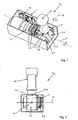
- an apparatus R 1 has a housing 1 in which a first guide element 3.1 is arranged so as to be rotatable about an axis A on an end wall 2.
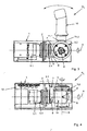
- the guide element 3.1 is connected to a drive device 4.1, in particular a preferably electrically operated drive motor 5.1 and a subsequent transmission 6.1 in combination, as shown in more detail in Figures 3 and 4.
- the guide element 3.1 in the preferred embodiment, a holding arm 7, which runs out of the axis A approximately at right angles by means of a holding plate 8 and forms a right angle with a thereto approximately at a right angle receiving plate 9.
- the receiving plate 9 extends approximately parallel to the axis A.
- a second guide element 3.2 is preferably mounted at right angles to the axis A, which is rotatably supported about the axis B via a second drive means 4.2, in particular drive motor 5.2.
- intersection S between the two axes A and B is preferably the fulcrum P of a handle 10, which approximately perpendicular to the second guide member 3.2 rests perpendicular projecting upwards.
- At least one force sensor 11.1, 11.2 can be associated with the handle 10 and / or the guide element 3.2, as shown in particular in FIGS. 1 to 3.
- the force sensor 11.1. 11.2 has the task of manually moving the handle 10 to detect a force and a direction of movement to a forced guidance or a supported movement of the handle 10 in the respective desired direction by corresponding rotation of the guide elements 3.1, 3.2 by means of the drive 4.1 To allow 4.2.
- FIG 5 shows that the guide element 3.1 is mounted on one side via bearing elements 13 relative to the housing 1.
- bearing elements 13 can be used, so that the guide element 3.1 one side about the axis A rotatable relative to the housing 1 can be stored.
- the bearing elements 13 can absorb large forces.
- the guide element 3.1 includes as its part of the support arm 7 at an angle.
- the holding plate 8 is seated on which off-center to the axis A and approximately parallel to the axis A, the receiving plate 9 connects.
- bearing elements 14 are arranged, which store the guide member 3.2 rotatable and pivotable about the axis B.
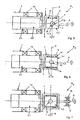
- a device R 2 is shown in which essentially all the components described above are included according to FIGS. 1 to 5. It is different that the guide element 3.2 with integrated drive device 4.2 at both ends is rotatably mounted relative to the support arm 7 via additional bearing elements 14 about the axis B. A two-sided storage is realized here. For this purpose, another receiving plate 9 adjoins the holding plate 8 at the other end.
- a device R 3 is shown, in which according to the embodiment according to Figure 6, although the guide elements 3.2 are mounted on both sides about the axis B, but the support arm 7 not only at one end on the bearing elements 13 but also at the other end via further bearing elements 13, as schematically indicated here about the axis A is rotatably mounted. At a two-sided storage is thought here.
- a device R 4 is shown, in which the guide element 3.2 according to the embodiment of the device R 1 according to Figure 5 is mounted on one side about the axis B rotatable.
- a device R 5 which essentially corresponds to its construction of the device according to FIGS. 1 to 4,
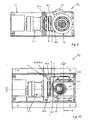
- a stop element 15.1 is arranged on the holding plate 8, which limits a rotational movement of the guide element 3.2 with respect to its end positions.
- Corresponding Stopperlemente 16.1, 16.2 can limit the movement of the guide element 3.1, 3.2. These close the front side of the guide element 3.2.
- stop element 15.1 and stopper element 16.1, 16.2 are arranged approximately near the axis A within the holding plate 8 of the holding arm 7.
- another stop element 15.2 is preferably fixed to the end wall 2 of the housing 1, with the two radially on the holding plate 8 of the holding arm 7 rear side stopper elements 16.3, 16.4 a direction of movement of the guide element 3.1 about the axis A. to restrict.
- An advantage of the present invention is that each direction of movement of the guide elements 3.1, 3.2 is independent either about the axis A or about the axis B and the two stop elements 15.1, 15.2 are not coupled together.
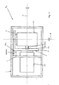
- the operation of the device R 5 is shown schematically as a plan view.
- the movement of the guide element 3.1, about the axis A by the stop element 15.2 which end side of the holding plate 8 and / or the receiving plate 9 is disposed opposite to two arranged on the end wall 2 of the housing 1 stopper elements 16.3, 16.4, as well as in Figure 12th shown limited.
- the stopper elements 16.1 to 16.4 can have corresponding adjusting devices in order to limit an exact stop accordingly.
- the stopper elements 16.1 to 16.4 and also the stop elements 15.1, 15.2 may be made of nylon, metal or the like. Materials may also be made in combination. It is also contemplated to attenuate the respective SLopper electrode 16.1 to 16.4 to attenuate an impact on a stop.
Landscapes
- Physics & Mathematics (AREA)
- General Physics & Mathematics (AREA)
- Engineering & Computer Science (AREA)
- Automation & Control Theory (AREA)
- Toys (AREA)
- Manipulator (AREA)
- Transmission Devices (AREA)
- Mechanical Control Devices (AREA)
Claims (11)
- Dispositif de commande d'un appareil, tel que par exemple un avion, un simulateur de vol, un robot ou autre, avec une poignée (10) qui est mobile autour de deux axes (A, B) perpendiculaires entre eux,
caractérisé par le fait que
à la poignée (10) est associé au moins un capteur de force (11.1, 11.2) destiné à commander et/ou à régler un mouvement d'éléments de guidage (3.1, 3.2) sur les axes (A, B) et que les éléments de guidage (3.1, 3.2) montés dans les axes (A, B) peuvent être entraînés séparément, chacun par l'intermédiaire un dispositif d'entraînement (4.1, 4.2) intégré dans ces derniers. - Dispositif selon la revendication 1, caractérisé par le fait que la poignée (10) est montée autour d'un point de rotation (P) correspondant à une intersection (S) des axes (A, B), un élément de guidage (3.1) étant monté dans un boîtier (1) et qu'en dehors du boîtier (1) est prévu un bras de support (7) disposé à angle avec une branche excentrée par rapport à l'axe (A), auquel est raccordé, perpendiculairement à l'axe (A), le deuxième élément de guidage (3.2) de manière rotative autour de l'axe (B), et que le premier élément de guidage (3.1) est monté, par l'intermédiaire d'éléments de roulement (13), de manière rotative autour de l'axe (A), d'un côté par rapport au boîtier (1).
- Dispositif selon au moins l'une des revendications 1 ou 2, caractérisé par le fait que le dispositif d'entraînement (4.1, 4.2) présente un moteur d'entraînement (5.1, 5.2) et éventuellement un engrenage (6.1, 6.2).
- Dispositif selon au moins l'une des revendications 1 à 3, caractérisé par le fait que les dispositifs d'entraînement (4.1, 4.2), les moteurs d'entraînement (5.1, 5.2), les engrenages (6.1, 6.2) ainsi que l'au moins un capteur de force (11.1, 11.2) sont reliés à une commande (12).
- Dispositif selon au moins l'une des revendications 2 à 4, caractérisé par le fait que le deuxième élément de guidage (3.2) est monté perpendiculairement au premier élément de guidage (3.1) par rapport à son bras de support (7), par l'intermédiaire d'autres éléments de roulement (14).
- Dispositif selon au moins l'une des revendications 2 à 5, caractérisé par le fait que le deuxième élément de guidage (3.2) est monté d'un côté au bras de support (7), de manière excentrique par rapport à l'axe (A), de manière rotative autour de l'axe (B).
- Dispositif selon au moins l'une des revendications 2 à 6, caractérisé par le fait que le bras de support (7) est monté de part et d'autre autour, de l'axe (A).
- Dispositif selon au moins l'une des revendications 2 à 7, caractérisé par le fait que le bras de support (7) est réalisé en forme de U, entre lequel est monté, des deux côtés, le deuxième élément de guidage (3.2) de manière excentrée par rapport à l'axe (A), de manière rotative autour de l'axe (B).
- Dispositif selon au moins l'une des revendication 2 à 8, caractérisé par le fait que le bras de support (7) est monté de manière rotative des deux côtés autour de l'axe (A) et qu'à ce dernier est monté des deux côtés le deuxième élément de guidage (3.2), de manière rotative autour de l'axe (B).
- Dispositif selon au moins l'une des revendications 1 à 9, caractérisé par le fait que le premier élément de guidage (3.1) avec un élément de butée (15.2) est pivotable de manière limitée autour de l'axe (A) par rapport à au moins un élément d'arrêt (16.3, 16.4) et/ou que le deuxième élément de guidage (3.2) est pivotable de manière limitée autour de l'axe (B) avec au moins un élément d'arrêt (16.1, 16.2) par rapport à au moins un élément de butée (15.1), sans que ne soit chaque fois limitée ou réduite la liberté de mouvement de l'autre axe (A ou B), et est disposé, pour limiter le mouvement de l'élément de guidage (3.1) autour de l'axe (A) sur une plaque de réception (9) du bras de support (7), au moins un élément d'arrêt (16.3, 16.4) approprié étant associé à une paroi latérale (2) du boîtier (1).
- Dispositif selon la revendication 10, caractérisé par le fait que les éléments d'arrêt (16.1 à 16.4) limitent de manière réglable un trajet des éléments de butée (15.1, 15.2) et sont éventuellement munis d'un dispositif d'ajustage en vue du réglage fin des positions de fin de course.
Applications Claiming Priority (3)
| Application Number | Priority Date | Filing Date | Title |
|---|---|---|---|
| DE19926784A DE19926784A1 (de) | 1999-06-11 | 1999-06-11 | Vorrichtung zum Steuern einer Einrichtung |
| DE19926784 | 1999-06-11 | ||
| EP00943765A EP1185912B1 (fr) | 1999-06-11 | 2000-06-06 | Dispositif de commande d'un appareil |
Related Parent Applications (1)
| Application Number | Title | Priority Date | Filing Date |
|---|---|---|---|
| EP00943765A Division EP1185912B1 (fr) | 1999-06-11 | 2000-06-06 | Dispositif de commande d'un appareil |
Publications (2)
| Publication Number | Publication Date |
|---|---|
| EP1528449A1 EP1528449A1 (fr) | 2005-05-04 |
| EP1528449B1 true EP1528449B1 (fr) | 2006-03-29 |
Family
ID=7911002
Family Applications (2)
| Application Number | Title | Priority Date | Filing Date |
|---|---|---|---|
| EP00943765A Expired - Lifetime EP1185912B1 (fr) | 1999-06-11 | 2000-06-06 | Dispositif de commande d'un appareil |
| EP05002529A Expired - Lifetime EP1528449B1 (fr) | 1999-06-11 | 2000-06-06 | Dispositif de commande d'un appareil |
Family Applications Before (1)
| Application Number | Title | Priority Date | Filing Date |
|---|---|---|---|
| EP00943765A Expired - Lifetime EP1185912B1 (fr) | 1999-06-11 | 2000-06-06 | Dispositif de commande d'un appareil |
Country Status (4)
| Country | Link |
|---|---|
| US (1) | US6708580B1 (fr) |
| EP (2) | EP1185912B1 (fr) |
| DE (3) | DE19926784A1 (fr) |
| WO (1) | WO2000077589A1 (fr) |
Families Citing this family (13)
| Publication number | Priority date | Publication date | Assignee | Title |
|---|---|---|---|---|
| DE10258197A1 (de) * | 2002-12-12 | 2004-07-08 | Tonic Fitness Technology, Inc., Hsi Kang | Direkt angetriebene Antriebs-Schwingstangen-Einrichtung ohne Totpunkte |
| DE10305261A1 (de) * | 2003-02-07 | 2004-08-26 | Wittenstein Ag | Vorrichtung zum Steuern eines Fahrzeuges |
| US7701161B2 (en) | 2006-10-02 | 2010-04-20 | Honeywell International Inc. | Motor balanced active user interface assembly |
| WO2009016361A2 (fr) * | 2007-07-31 | 2009-02-05 | Wittenstein Aerospace & Simulation Limited | Dispositif de commande |
| GB0714916D0 (en) | 2007-07-31 | 2007-09-12 | Wittenstein Aerospace & Simula | Control device |
| US8096206B2 (en) * | 2007-12-05 | 2012-01-17 | Liebherr-Aerospace Lindenberg Gmbh | Control device |
| US20090266948A1 (en) * | 2008-04-29 | 2009-10-29 | Honeywell International Inc. | Human-machine interface two axis gimbal mechanism |
| DE202017105886U1 (de) | 2017-09-27 | 2017-11-29 | Spohn & Burkhardt GmbH & Co. KG | Schalteinrichtung |
| CN112870630B (zh) * | 2021-02-04 | 2022-10-04 | 李从宇 | 一种适用于残障人士的神经科用下肢康复训练器 |
| US12158388B2 (en) * | 2021-03-30 | 2024-12-03 | Cae Inc. | Calibration adaptor bracket, apparatus and method |
| DE102022134686A1 (de) * | 2022-12-22 | 2024-06-27 | Inventus Engineering Gmbh | Bedieneinrichtung mit wenigstens einem schwenkbaren Bedienhebel |
| WO2024156994A1 (fr) * | 2023-01-25 | 2024-08-02 | Bae Systems Plc | Agencement de manette active et système de commande |
| EP4406847A1 (fr) * | 2023-01-25 | 2024-07-31 | BAE SYSTEMS plc | Agencement de papillon actif et système de commande |
Family Cites Families (10)
| Publication number | Priority date | Publication date | Assignee | Title |
|---|---|---|---|---|
| US3776058A (en) * | 1972-05-17 | 1973-12-04 | Us Navy | Multi-axis hand controller |
| US4704798A (en) * | 1976-07-06 | 1987-11-10 | Hird Edwin A | Measurement digitizer |
| SE436154B (sv) | 1980-01-24 | 1984-11-12 | Olsbergs Hydraulic Ab | Anordning for att styra medietillforseln till ett antal forbrukare |
| JPS5868634U (ja) * | 1981-10-31 | 1983-05-10 | テクトロニクス・インコ−ポレイテツド | ジヨイステイツク |
| DE3404047A1 (de) | 1984-02-06 | 1985-08-08 | Siemens AG, 1000 Berlin und 8000 München | Steuerstab |
| FR2590044B1 (fr) | 1985-09-27 | 1988-01-29 | Applic Mach Motrices | Dispositif de commande electrique motorise |
| JP2996930B2 (ja) * | 1997-04-04 | 2000-01-11 | 三和電子株式会社 | ジョイスティックコントローラー |
| DE19818866C1 (de) * | 1998-04-28 | 1999-11-11 | Daimler Chrysler Ag | Wähleinrichtung für ein automatisches Kraftfahrzeuggetriebe |
| US6128971A (en) * | 1998-12-21 | 2000-10-10 | Caterpillar Inc. | Control device |
| US6429849B1 (en) * | 2000-02-29 | 2002-08-06 | Microsoft Corporation | Haptic feedback joystick |
-
1999
- 1999-06-11 DE DE19926784A patent/DE19926784A1/de not_active Withdrawn
-
2000
- 2000-06-06 US US10/009,185 patent/US6708580B1/en not_active Expired - Lifetime
- 2000-06-06 EP EP00943765A patent/EP1185912B1/fr not_active Expired - Lifetime
- 2000-06-06 DE DE50012502T patent/DE50012502D1/de not_active Expired - Lifetime
- 2000-06-06 WO PCT/EP2000/005134 patent/WO2000077589A1/fr not_active Ceased
- 2000-06-06 DE DE50012165T patent/DE50012165D1/de not_active Expired - Lifetime
- 2000-06-06 EP EP05002529A patent/EP1528449B1/fr not_active Expired - Lifetime
Also Published As
| Publication number | Publication date |
|---|---|
| EP1185912A1 (fr) | 2002-03-13 |
| DE50012165D1 (de) | 2006-04-13 |
| WO2000077589A1 (fr) | 2000-12-21 |
| DE19926784A1 (de) | 2000-12-14 |
| EP1185912B1 (fr) | 2006-02-01 |
| EP1528449A1 (fr) | 2005-05-04 |
| DE50012502D1 (de) | 2006-05-18 |
| US6708580B1 (en) | 2004-03-23 |
Similar Documents
| Publication | Publication Date | Title |
|---|---|---|
| DE2301423C3 (de) | Handhabungsgerät | |
| EP1528449B1 (fr) | Dispositif de commande d'un appareil | |
| DE2751579C2 (de) | Motorgetriebener Manipulator | |
| DE2852635C3 (de) | Vorderradantrieb für ein fernlenkbares Spielfahrzeug | |
| EP1152182A1 (fr) | Microscope chirurgical | |
| AT502864A2 (de) | Parallelkinematischer roboter | |
| DE3124181A1 (de) | "lenkvorrichtung fuer lenkspindel fuer fahrzeuge insbesondere kraftfahrzeuge" | |
| DE102016210498A1 (de) | Patientenpositioniervorrichtung und medizinischer Arbeitsplatz | |
| EP1433576B1 (fr) | Robot de type à bras articulé muni d'un laser disposé au niveau de son deuxième axe | |
| DE4041676A1 (de) | Einstellbarer fahrzeugscheinwerfer | |
| DE60302802T2 (de) | Transportvorrichtung mit untergeordneter steuerung | |
| EP3343311B1 (fr) | Levier de commande pourvu d'unité de rétroaction active | |
| EP0319885A1 (fr) | Simulateur de thérapie | |
| EP1216787A1 (fr) | Dispositif de positionnement | |
| DE3504233A1 (de) | Greiferarm fuer handhabungsgeraete | |
| DE3513056A1 (de) | Gelenk-antriebsanordnung | |
| DE102019126390A1 (de) | Flurgebundenes Fahrzeug | |
| DE10257631B4 (de) | Verstellbares Fußhebelwerk | |
| DE69411370T2 (de) | Einschlaggraviervorrichtung | |
| EP0960850A2 (fr) | Chariot de manutention, en particulier élévateur à fourche à siège frontale | |
| DE29917818U1 (de) | Vorrichtung zum Steuern einer Einrichtung | |
| DE69004666T2 (de) | Fahrzeug für Einsätze, insbesondere in Gebäuden. | |
| DE102006022242B4 (de) | Verfahrsystem | |
| EP1878964A2 (fr) | Chariot de caméra doté de roues avant et/ou arrière orientables | |
| EP1601571B1 (fr) | Dispositif de commande d'un vehicule |
Legal Events
| Date | Code | Title | Description |
|---|---|---|---|
| PUAI | Public reference made under article 153(3) epc to a published international application that has entered the european phase |
Free format text: ORIGINAL CODE: 0009012 |
|
| AC | Divisional application: reference to earlier application |
Ref document number: 1185912 Country of ref document: EP Kind code of ref document: P |
|
| AK | Designated contracting states |
Kind code of ref document: A1 Designated state(s): DE FR GB IT |
|
| 17P | Request for examination filed |
Effective date: 20050618 |
|
| GRAP | Despatch of communication of intention to grant a patent |
Free format text: ORIGINAL CODE: EPIDOSNIGR1 |
|
| GRAS | Grant fee paid |
Free format text: ORIGINAL CODE: EPIDOSNIGR3 |
|
| AKX | Designation fees paid |
Designated state(s): DE FR GB IT |
|
| GRAA | (expected) grant |
Free format text: ORIGINAL CODE: 0009210 |
|
| AC | Divisional application: reference to earlier application |
Ref document number: 1185912 Country of ref document: EP Kind code of ref document: P |
|
| AK | Designated contracting states |
Kind code of ref document: B1 Designated state(s): DE FR GB IT |
|
| REG | Reference to a national code |
Ref country code: GB Ref legal event code: FG4D Free format text: NOT ENGLISH |
|
| GBT | Gb: translation of ep patent filed (gb section 77(6)(a)/1977) |
Effective date: 20060329 |
|
| REF | Corresponds to: |
Ref document number: 50012502 Country of ref document: DE Date of ref document: 20060518 Kind code of ref document: P |
|
| ET | Fr: translation filed | ||
| PLBE | No opposition filed within time limit |
Free format text: ORIGINAL CODE: 0009261 |
|
| STAA | Information on the status of an ep patent application or granted ep patent |
Free format text: STATUS: NO OPPOSITION FILED WITHIN TIME LIMIT |
|
| 26N | No opposition filed |
Effective date: 20070102 |
|
| PGFP | Annual fee paid to national office [announced via postgrant information from national office to epo] |
Ref country code: FR Payment date: 20090615 Year of fee payment: 10 Ref country code: IT Payment date: 20090624 Year of fee payment: 10 |
|
| PGFP | Annual fee paid to national office [announced via postgrant information from national office to epo] |
Ref country code: GB Payment date: 20090618 Year of fee payment: 10 |
|
| GBPC | Gb: european patent ceased through non-payment of renewal fee |
Effective date: 20100606 |
|
| REG | Reference to a national code |
Ref country code: FR Ref legal event code: ST Effective date: 20110228 |
|
| PG25 | Lapsed in a contracting state [announced via postgrant information from national office to epo] |
Ref country code: IT Free format text: LAPSE BECAUSE OF NON-PAYMENT OF DUE FEES Effective date: 20100606 |
|
| PG25 | Lapsed in a contracting state [announced via postgrant information from national office to epo] |
Ref country code: FR Free format text: LAPSE BECAUSE OF NON-PAYMENT OF DUE FEES Effective date: 20100630 |
|
| PG25 | Lapsed in a contracting state [announced via postgrant information from national office to epo] |
Ref country code: GB Free format text: LAPSE BECAUSE OF NON-PAYMENT OF DUE FEES Effective date: 20100606 |
|
| REG | Reference to a national code |
Ref country code: DE Ref legal event code: R082 Ref document number: 50012502 Country of ref document: DE Representative=s name: PATENTANWAELTE UND RECHTSANWALT DR. WEISS, ARA, DE Ref country code: DE Ref legal event code: R082 Ref document number: 50012502 Country of ref document: DE Representative=s name: PATENTANWAELTE UND RECHTSANWALT WEISS, ARAT & , DE |
|
| REG | Reference to a national code |
Ref country code: DE Ref legal event code: R082 Ref document number: 50012502 Country of ref document: DE Representative=s name: PATENTANWAELTE UND RECHTSANWALT WEISS, ARAT & , DE Ref country code: DE Ref legal event code: R081 Ref document number: 50012502 Country of ref document: DE Owner name: WITTENSTEIN SE, DE Free format text: FORMER OWNER: WITTENSTEIN AG, 97999 IGERSHEIM, DE |
|
| PGFP | Annual fee paid to national office [announced via postgrant information from national office to epo] |
Ref country code: DE Payment date: 20190827 Year of fee payment: 20 |
|
| REG | Reference to a national code |
Ref country code: DE Ref legal event code: R071 Ref document number: 50012502 Country of ref document: DE |