EP1528713A2 - Télésurveillance de terminaux graphiques de télécommunications - Google Patents
Télésurveillance de terminaux graphiques de télécommunications Download PDFInfo
- Publication number
- EP1528713A2 EP1528713A2 EP04024132A EP04024132A EP1528713A2 EP 1528713 A2 EP1528713 A2 EP 1528713A2 EP 04024132 A EP04024132 A EP 04024132A EP 04024132 A EP04024132 A EP 04024132A EP 1528713 A2 EP1528713 A2 EP 1528713A2
- Authority
- EP
- European Patent Office
- Prior art keywords
- terminal
- graphical
- monitoring
- monitored
- user
- Prior art date
- Legal status (The legal status is an assumption and is not a legal conclusion. Google has not performed a legal analysis and makes no representation as to the accuracy of the status listed.)
- Withdrawn
Links
Images


Classifications
-
- H—ELECTRICITY
- H04—ELECTRIC COMMUNICATION TECHNIQUE
- H04L—TRANSMISSION OF DIGITAL INFORMATION, e.g. TELEGRAPHIC COMMUNICATION
- H04L43/00—Arrangements for monitoring or testing data switching networks
-
- H—ELECTRICITY
- H04—ELECTRIC COMMUNICATION TECHNIQUE
- H04L—TRANSMISSION OF DIGITAL INFORMATION, e.g. TELEGRAPHIC COMMUNICATION
- H04L41/00—Arrangements for maintenance, administration or management of data switching networks, e.g. of packet switching networks
- H04L41/22—Arrangements for maintenance, administration or management of data switching networks, e.g. of packet switching networks comprising specially adapted graphical user interfaces [GUI]
-
- H—ELECTRICITY
- H04—ELECTRIC COMMUNICATION TECHNIQUE
- H04L—TRANSMISSION OF DIGITAL INFORMATION, e.g. TELEGRAPHIC COMMUNICATION
- H04L43/00—Arrangements for monitoring or testing data switching networks
- H04L43/10—Active monitoring, e.g. heartbeat, ping or trace-route
- H04L43/106—Active monitoring, e.g. heartbeat, ping or trace-route using time related information in packets, e.g. by adding timestamps
Definitions
- This invention relates in general to telecommunications and, more particularly, to a digital communications network.
- a communications system includes a data network and a monitored terminal coupled to the network for communicating by sending and receiving data over the network.
- a monitoring terminal monitors user activity on the monitored terminal.
- a graphical proxy server in communication with the monitored terminal and with the monitoring terminal sends graphical commands to implement a graphical interface on the monitored terminal and sends graphical commands to the monitoring terminal indicative of actions taken on the monitored terminal.
- Figure 1 illustrates a block diagram of a VOIP network
- Figure 2 illustrates a basic block diagram of a system for remote monitoring of a communication session
- Figure 3 illustrates a block diagram of a graphical proxy server
- Figure 4 illustrates a block diagram of terminal controller used in the graphical proxy and it interaction with other components of the graphical proxy
- Figure 5 illustrates a block diagram of a graphical client of a graphical terminal associated with a graphical proxy server.
- Figure 6 illustrates the steps for registration/log-in
- Figure 7 illustrates a call flow for an outgoing call from a terminal
- Figure 8 illustrate a call flow for putting a caller on hold
- Figure 9 illustrates a flow chart describing operation of the block diagram of Figure 3 in a monitoring mode.
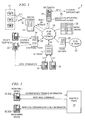
- FIG. 1 illustrates a block diagram of a VOIP network 8 of the type described in U.S. Ser. No. 10/092,075, entitled “Graphical Telephone System", filed March 6, 2002 to Ransom, which is incorporated by reference herein.
- a packet-based network 10 is the main carrier of telecommunications traffic.
- the network 10 could use, for example, IP (Internet Protocol) or ATM (Asynchronous Transfer Mode).
- Legacy telephone equipment 12 i.e., present-day telephones and similar equipment compatible with the public switched telephone network
- the access gateways 14 interface between the analog legacy telephone equipment and the network 10, using a protocol such as MGCP (Media Gateway Control Protocol) or MEGACO (H.248).
- MGCP Media Gateway Control Protocol
- MEGACO H.248
- SIP telephones 18 (or other VOIP phones, such as H.323 phones) and SIP proxy server 19 can be connected directly to the network 10.
- SIP telephones 18 are intelligent devices that contain processors that are independent from a central switching location (i.e., a central office) and have one or more processors to create, modify and terminate communication sessions.
- a trunk gateway 20 provides an interface between the packet network 10 and the PSTN (public switched telephone network) 22.
- Softswitches 24, application servers 26 and media servers 28 are instrumental in providing advanced functions.
- a softswitch 24 is a software-based entity that provides call control functionality.
- a softswitch 24 may support multiple packet-based protocols, such as SIP, MGCP, MEGACO and multiple telephony and data protocols, such as CAS, INAP, ISDN, SS7, TCAP, TCP/IP.
- a softswitch 24 may interface with the PSTN 22 through various gateways.
- a softswitch 24 may act as a SIP proxy server for name resolution and user location - similar to a domain server.
- a name (similar to a domain name) can be dynamically associated with a current IP address.
- a SIP proxy server may be used for redirection of packets, where the proxy server "pretends" to the other network elements that it is the user's SIP terminal and forwards messages to the real SIP terminal (or conceivably to another SIP Proxy).
- Application servers 26 provide services that may result in termination of a call, such as voice mail, conference bridging, pre-paid calling, or delivering services and information to an end user.
- An application server can be coupled to other data networks, such as the Internet, to gain access to information systems.
- Media servers 26 provide media processing under control of a media gateway controller (not shown).
- the media server 26 could provide, for example, voice storage and responses for voice mail, or video streams.
- Graphical terminals (described below) 32 communicate with an associated graphical proxy 34 with other SIP phones (and similar VOIP devices) over the network 10 using a graphics protocol between the graphics terminals 32 and the graphical proxy 34, where the graphics protocol controls the GUI of the graphics terminal and provides control information to the graphical proxy 34 regarding a user's actions with the packet phone's GUI.
- the graphical proxy 34 communicates with other devices over the network using SIP (or similar protocol).
- U.S. Ser. No. 10/092,075 describes the use of a graphical proxy 34 to control the GUI of a "dumb" packet phone, rather than an "intelligent" SIP phone. Responsive to actions by the user, the graphical proxy sends commands to the dumb packet phone to control the operation of the user interface, as opposed to the SIP phone controlling the user interface internally. This provides a significant advantage over the prior art, since the network provider could control the GUI of the packet telephones to add value to its network services and can improve the consistency of the user interface between phones.
- a large class of computing devices could function as a graphics terminal 32, even though these devices do not have the client communication stack normally associated with a packet phone.
- a graphics terminal 32 includes sound and display capabilities, with network communications functionality.
- Devices of this type would include personal computers (including desktop and portable computers), personal digital assistants (PDAs, including pocket PCs) and so on. It is assumed that these devices include browser software with pluggable and downloadable MACROMEDIA FLASH (or other interactive graphics design software) and have a TCP/IP and RTP (Real-time Transport Protocol) stack.
- FIG. 2 illustrates a basic block diagram of a system for remote monitoring of a communication session.
- a monitored terminal 32a is coupled to the graphical proxy 34 along with a monitoring terminal 32b. It is assumed that the monitoring terminal 32b has registered with the graphical proxy 34 to allow monitoring of the monitored terminal 32a. With law enforcement, registration would be made through the service provider that controls the graphical proxy 34. In other cases, the owner of the monitored terminal 32a (for example, a parent or business owner) could register directly with the graphical proxy 34.
- the graphical proxy 34 In operation, when there is activity on the graphical interface of the monitored terminal 32a, the graphical proxy 34 sends graphical commands to both the monitored terminal 32a and the monitoring terminal 32b. From the viewpoint of the user of the monitored terminal 34a, operation of the telephone is normal, and the user interacts with the user interface to operate the device 32a to create and terminate connections with other devices in the telecommunications network 8. Additionally, the monitored terminal 32a may send presence information, discussed below, to the graphical proxy 34.
- the monitoring terminal 32b receives the same graphical commands as the monitored terminal 32a and thus displays actions being performed on the monitored terminal 32a, allowing the user of the monitoring terminal 32b to visually observe the activity on the monitored terminal 32a.
- the monitoring terminal 32b may also receive presence information associated with the monitored terminal.
- the remote monitoring system of Figure 2 could assume several different modes of operation.
- First, graphical commands could be sent simultaneously from the graphical proxy 34 to both the monitored terminal 32a and monitoring terminal 32b, such that the monitoring terminal 32b observes real-time operation of the monitored terminal 32a.
- the graphical proxy 34 could store the graphical commands from a communication session, and optionally time-stamp the commands, such that an authorized observer could observe the communication session at a later time (or archive the communications sessions).
- the graphical proxy 34 could send the graphical commands from a communication session to the monitoring terminal 34b in real-time, or near real-time, and the monitoring terminal could save the graphical commands for later playback.
- the monitored terminal 32a could be identified by the user of the monitoring terminal 32b by IP address or a name mapped to the IP address, or the monitored terminal 32 could be a terminal currently being used by a particular user identified by the user of the monitoring terminal 32b.
- Figures 3-8 illustrate an embodiment of a graphical proxy which could be used to implement the monitoring capabilities shown in Figure 2. Other architectures could also be used.
- Figure 3 illustrates a block diagram of a graphical proxy 34 which could be used to coordinate remote monitoring as described above.
- the graphical proxy 34 of Figure 3 preferably supports graphical terminals 32 that do not have a client communication stack, as described in detail in connection with U.S. Ser. No. 10/317,447, entitled, "GRAPHICAL PROXY FOR LESS CAPABLE TERMINALS" to Suhail et al filed December 12, 2002, which is incorporated by reference herein.
- the graphical proxy 34 includes two major functional blocks, a graphical server 40 and a terminal management system 42.
- the graphical server 40 includes a request parser 44, a GUI generator 46 and a GUI customizer 48.
- the terminal management system 42 includes a terminal manager 50, a SIP stack 52, a translator 54, and multiple instances of terminal controllers 56, where each instance of a terminal controller 56 is associated with a respective graphical terminal 32.
- the graphical server 40 and the terminal management system 42 are in communication with a database 58.
- three graphical terminals are shown: a personal computer 32a, a generic processing device 32b and a PDA 32c.
- Each graphical terminal 32 includes graphical client software 60 and GUI software 62.
- Any one of the graphical terminals 32 shown in Figure 3 could be either the monitored terminal 32a or the monitoring terminal 32b.
- the monitoring terminal 32b does not need to all the capabilities of a typical terminal 32, since it does not necessarily need to send or receive packetized data.
- the monitoring terminal 32b could be any general computing device, with or without audio input or output capabilities.
- the terminal management system 42 is responsible for registering the associated graphical terminals 32 with the graphical proxy 34 and then registering on behalf of each associated graphical terminal 32 with the SIP Proxy 19.
- the terminal management system 42 handles the calls for each associated graphical terminal 32 and interacts with the graphical server 40 to provide a customized GUI for each graphical terminal 32 to display current call status.
- the terminal manager 50 manages all the associated graphical terminals 32.
- the graphical terminal establishes a connection with the terminal manager 50.
- the terminal manager 50 then instantiates a terminal controller 56 for that graphical terminal 32 and maintains the mapping between the graphical terminal 32 and the respective terminal controller 50.
- the terminal manager 50 implements a Super user agent 64, which receives requests for connection for all terminals 32, identifies which terminal is associated with the request, and then passes the request to the user agent 66 (see Figure 4) in the terminal controller 56 for the particular terminal.
- the Super User Agent 64 passes requests to the user agents 66 associated with both the monitored terminal 32a and the monitoring terminal 32b.
- the Super User Agent 64 is also responsible for registering each terminal 32 with the SIP Proxy server 19. To the SIP proxy server 19, the Super user agent 64 appears as the individual user agent for a terminal.
- FIG. 4 shows different components of the terminal controller 56 and their interaction with other components of the graphical proxy 34.
- Each terminal controller 56 includes a user agent 66, a call control system 68 and a presentation manager 70.
- the User agent 66 receives and sends SIP messages on behalf of the associated graphical terminal 32 (while the present invention is described in connection with the SIP protocol, the user agents 66 could support any available protocol, such as H.323, MGCP, MEGACO, any protocol developed in the future, or multiple protocols).
- the user agent 66 processes SIP requests and response messages coming to the terminal 32 and provides relevant information to the call control system 68.
- the user agent 66 when the user agent 66 receives an INVITE message for its terminal 32, it processes that message and informs the call control system 68 that there is a request for connection or incoming call for its associated terminal 32 from Caller X and the desired media for communication. The user agent 66 also generates appropriate SIP requests and response messages based on the information it gets from the call control system 68 responsive to user responses.
- the call control system 68 handles incoming and outgoing calls for its associated terminal 32 and manages all active calls. It gets information on the incoming messages from the user agent 66 and provides information on user responses back to the user agent. The call control system 68 also generates service requests and sends them to the graphical server 40 to get a URL (Uniform Resource Locator) for an appropriate FLASH page displaying the desired user interface screen.
- URL Uniform Resource Locator
- the call control system 68 For example, if there is an incoming call, the call control system 68 generates a request to "show incoming call". The graphical server 40 then returns the URL of the FLASH page with the display for an incoming call.
- the incoming call FLASH page may include multiple graphical elements, but will not include specific text relevant to the current call, such as the name of the caller.
- the call control system 68 assembles the URL and the data that has to be filled in the FLASH page such as the Callers and Callee's name in the form of XML message and passes it to the presentation manager 70.
- the FLASH client 60 on the associated terminal 32 has a built in XML parser 61; it loads the FLASH page from the given URL and fills the fields with the data provided in the XML message.
- the call control system 68 also receives GUI response messages from the terminal 32 through the presentation manager 70 and invokes the translator 54 to parse the XML messages and translate them to JAVA objects that can be used by the call control system 68.
- the call control system 68 also sends RTP setup and RTP tear down messages to the RTP controller 74 (See Figure 5) through FLASH on the terminal.
- RTP setup message is sent when the call setup is complete and the terminal has to set up RTP session with the remote party to start sending/receiving media.
- RTP tear down message is sent to the terminal if the user at the terminal or the remote party ends the call.
- the presentation manager 70 manages the display of its associated terminal 32.
- the terminal 32 could support several "phone lines "; in other words a single terminal can handle more than one active call at a time.
- the presentation manager 70 maintains individual folders for different calls.
- the call control system 68 sends the graphical representation of call status for a particular call to the presentation manager 70.
- the presentation manager 70 decides where to display this graphical representation.
- the presentation manager 70 communicates with the graphical client 60 in FLASH through XML sockets.
- a copy of the XML socket is sent to the presentation manager 70 associated with the monitoring terminal 32b.
- the presentation manager 70 associated with the monitoring terminal 32b does not receive XML messages from the monitoring terminal 32b; i.e., the user of the monitored terminal 32b cannot interact with the call activity. Further, the user agent 66 associated with the monitored terminal 32b does not send outgoing SIP messages for the monitored call.
- the translator 54 translates the GUI response messages (indicating user actions, such as pressing a button or icon) coming from the terminal 32 in XML format to JAVA objects and translates JAVA objects to XML messages that have to be sent to the terminal 32.
- This two way mapping between JAVA and XML may be done using JAVA Architecture for XML Binding (JAXB).
- JAXB compiles an XML schema into one or more JAVA technology classes. The combination of the schema derived classes and the binding framework enables to perform the following operations on an XML document:
- the graphical server 40 generates the GUI for the terminals 32. For each associated terminal 32, the graphical server queries the database 58 to get the display capabilities of the terminal, such as size of the screen, depth of color etc. These capabilities are provided to the terminal manager 50 by the terminal 32 at the time of registration and stored in the database 58. When the graphical server 40 receives a request for a GUI, it customizes the GUI to the capabilities of the particular terminal.
- the graphical server 40 includes a GUI generator 46 and a GUI customizer 48.
- the GUI generator 46 stores a stack of static FLASH pages.
- the request parser 44 parses the service requests coming from the terminal controllers 56. Based on the particular service request, the GUI generator returns an appropriate FLASH page URL to the requesting terminal controller 56.
- the GUI customizer 48 customizes a selected FLASH page based on the capabilities of the particular graphical terminal 32.
- the graphical proxy 34 uses the database 58 (which could be part of the graphical proxy 34 or a separate device) to store user related information.
- the information stored in the database 58 includes: (1) user name and password of registered users, (2) current IP address of active registered users; (3) display capabilities of different terminals such as size of the screen color depth, etc., (4) media features that the user would like to use for communication with the remote party and (5) telephony features that the user has subscribed to such as Call Forwarding, Conferencing, Breakout room etc.
- a graphical client application 60 runs on each terminal 32.
- Figure 5 illustrates a block diagram of the graphical client 60.
- the graphical client 60 includes: (1) A FLASH client 72 to establish a TCP/IP connection with the graphical proxy 34 and for loading the login FLASH page from the graphical server 40 and (2) an RTP controller 74 responsible for setting up and tearing down the RTP session between the terminal 32 connected to the graphical proxy 34 and the remote party terminal.
- the RTP session has to be set up by the terminal because media does not go through the graphical proxy. Since the call set-up and tear down is controlled by the graphical proxy 34, the graphical proxy sends messages to the RTP controller 72 on the terminal 32 regarding when to set up and break down the RTP session along with the required parameters.
- Figure 6 illustrates the steps for registration/log-in.
- the steps include:
- Figure 7 illustrates a call flow for an outgoing call from a terminal 32.
- FIG 8 illustrate a call flow for putting a caller on hold.
- the call flow associated with the "resume” action (by the user) and the “establish RTP connection” signal are not shown; this call flow would be similar to that shown between the initial “click on hold” action and the "stop RTP connection” signal.
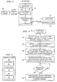
- Figure 9 illustrates a flow chart describing operation of the block diagram of Figure 3 in a monitoring mode.
- a user requests monitoring activity on another terminal or user.
- the graphical proxy requests information identifying the terminal/user to be monitored. This information is used to search database 58 to identify the address of the monitored terminal 32a and to verify that the user of the monitoring terminal has authorization to monitor the activity of the terminal/user.
- a terminal controller 56 is instantiated for the monitoring terminal 32b.
- the monitoring terminal 32b is registered with the Super User Agent 64 to identify the monitoring terminal 32b as a recipient of copies of SIP messages sent to the monitored terminal 32a.
- the monitoring terminal 32b is registered with the presentation manager 70 of the monitored terminal 32a to receive copies of XML objects from the monitored terminal 32a.
- the monitoring terminal 32b will have a display that mirrors the actions on the interface of the monitored terminal 32a. Since the monitoring terminal 32b has its own terminal controller 56, however, the display will be optimized for the capabilities of the monitoring terminal 32b.
- the monitoring station 32b may provide a notification when the monitored station receives or initiates a call.
- each call will have a separate folder in the presentation manager 70 of the monitoring station 72.
- the monitoring station 32b could be allowed to bridge into a communication session established by a monitored terminal 32a, i.e., the monitoring terminal 32a could receive voice packets as well has display information.
- the recording of the conversation could be done in the monitored terminal 32a in an audio file, such as a .WAV or .MP3 file; and this file could be transmitted to the monitoring terminal 32b upon completion of the conversation, or intermittently during the conversation (to avoid detection).
- the program for recording and transmitting the conversation could be initiated by the graphical proxy 34.
- the SIP messages and XML objects sent to the terminal controller 56 of the monitored terminal 32a can be time stamped and stored in a file.
- the XML objects received by the monitoring terminal 32b can be time stamped and stored in a file on the monitoring terminal 32b.
- the monitoring terminal could also perform presence monitoring.
- the monitoring terminal 32b can receive information on the identity of any persons using the monitoring terminal 32a and the times of such use, how the monitoring terminal is used (i.e., what programs were used), and the identities of parties in communication with the monitoring terminal 32a, including web sites, new groups, other data networks, intermediate sites providing communication between two users, and other persons.
- the presence information can be transferred to the monitoring terminal 32b via the graphical proxy 34.
- the monitoring terminal 32b could use the presence information, for example, to indicate whether a co-worker is in his/her office, in a telephonic conversation, or otherwise occupied.
Landscapes
- Engineering & Computer Science (AREA)
- Computer Networks & Wireless Communication (AREA)
- Signal Processing (AREA)
- Human Computer Interaction (AREA)
- Telephonic Communication Services (AREA)
- Data Exchanges In Wide-Area Networks (AREA)
Applications Claiming Priority (2)
| Application Number | Priority Date | Filing Date | Title |
|---|---|---|---|
| US699409 | 1985-02-07 | ||
| US10/699,409 US20050114497A1 (en) | 2003-10-31 | 2003-10-31 | Remote monitoring of graphical telecommunications terminal |
Publications (2)
| Publication Number | Publication Date |
|---|---|
| EP1528713A2 true EP1528713A2 (fr) | 2005-05-04 |
| EP1528713A3 EP1528713A3 (fr) | 2006-12-20 |
Family
ID=34423451
Family Applications (1)
| Application Number | Title | Priority Date | Filing Date |
|---|---|---|---|
| EP04024132A Withdrawn EP1528713A3 (fr) | 2003-10-31 | 2004-10-09 | Télésurveillance de terminaux graphiques de télécommunications |
Country Status (2)
| Country | Link |
|---|---|
| US (1) | US20050114497A1 (fr) |
| EP (1) | EP1528713A3 (fr) |
Cited By (2)
| Publication number | Priority date | Publication date | Assignee | Title |
|---|---|---|---|---|
| CN103220181A (zh) * | 2013-04-27 | 2013-07-24 | 北京百度网讯科技有限公司 | 数据中心移动巡检系统、服务器、终端设备 |
| CN104897201A (zh) * | 2015-04-29 | 2015-09-09 | 深圳市共济科技有限公司 | 一种移动巡检终端外接件辅助巡检的方法及系统 |
Families Citing this family (11)
| Publication number | Priority date | Publication date | Assignee | Title |
|---|---|---|---|---|
| US8266266B2 (en) | 1998-12-08 | 2012-09-11 | Nomadix, Inc. | Systems and methods for providing dynamic network authorization, authentication and accounting |
| US8713641B1 (en) | 1998-12-08 | 2014-04-29 | Nomadix, Inc. | Systems and methods for authorizing, authenticating and accounting users having transparent computer access to a network using a gateway device |
| US7941520B1 (en) * | 2001-09-28 | 2011-05-10 | Bellsouth Intellectual Property Corp. | System and method for tracking telephone network capacity and equipment |
| US7917167B1 (en) * | 2003-11-22 | 2011-03-29 | Iwao Fujisaki | Communication device |
| US20060002403A1 (en) * | 2004-06-30 | 2006-01-05 | Glenayre Electronics, Inc. | Distributed IP architecture for telecommunications system |
| CA2576133C (fr) * | 2005-11-21 | 2012-01-24 | Bce Inc. | Methode, systeme et dispositif permettant d'annoncer l'information d'un demandeur par liaison televisee |
| US8689317B2 (en) | 2005-12-19 | 2014-04-01 | Level 3 Communications, Llc | Providing SIP signaling data for third party surveillance |
| US8611962B2 (en) * | 2007-06-29 | 2013-12-17 | Microsoft Corporation | Activity illumination |
| KR100960111B1 (ko) * | 2008-07-30 | 2010-05-27 | 한국전자통신연구원 | 리버스 캐싱 프록시를 이용한 웹 기반의 역추적 시스템 |
| US8966555B2 (en) | 2010-09-15 | 2015-02-24 | At&T Intellectual Property I, L.P. | Method and system for performance monitoring of network terminal devices |
| CN103780451B (zh) * | 2012-10-24 | 2018-12-28 | 南京中兴软件有限责任公司 | 互联网访问的控制方法及装置 |
Family Cites Families (11)
| Publication number | Priority date | Publication date | Assignee | Title |
|---|---|---|---|---|
| US4575827A (en) * | 1984-05-18 | 1986-03-11 | International Business Machines Corporation | Self-archiving data recording |
| US5835696A (en) * | 1995-11-22 | 1998-11-10 | Lucent Technologies Inc. | Data router backup feature |
| US6055552A (en) * | 1997-10-31 | 2000-04-25 | Hewlett Packard Company | Data recording apparatus featuring spatial coordinate data merged with sequentially significant command data |
| US7027398B2 (en) * | 2001-04-12 | 2006-04-11 | General Instrument Corporation | Method and apparatus for monitoring voice conversations from customer premises equipment |
| MXPA01000893A (es) * | 1998-07-27 | 2002-06-04 | Webtv Networks Inc | Acceso remoto a computadora. |
| US6470075B1 (en) * | 1999-06-08 | 2002-10-22 | Telefonaktiebolaget L M Ericsson (Publ) | Automatic monitoring service for telecommunications networks |
| US6978304B2 (en) * | 2000-05-26 | 2005-12-20 | Pearl Software, Inc. | Method of remotely monitoring an internet session |
| US7296070B2 (en) * | 2000-12-22 | 2007-11-13 | Tier-3 Pty. Ltd. | Integrated monitoring system |
| US20040049530A1 (en) * | 2001-06-11 | 2004-03-11 | Simon Lok | Distributed computer system using a graphical user interface toolkit |
| US6775362B1 (en) * | 2002-03-06 | 2004-08-10 | Alcatel | Graphical telephone system |
| US6853710B2 (en) * | 2002-07-17 | 2005-02-08 | Timothy M Harris | Telephone call messaging device |
-
2003
- 2003-10-31 US US10/699,409 patent/US20050114497A1/en not_active Abandoned
-
2004
- 2004-10-09 EP EP04024132A patent/EP1528713A3/fr not_active Withdrawn
Cited By (2)
| Publication number | Priority date | Publication date | Assignee | Title |
|---|---|---|---|---|
| CN103220181A (zh) * | 2013-04-27 | 2013-07-24 | 北京百度网讯科技有限公司 | 数据中心移动巡检系统、服务器、终端设备 |
| CN104897201A (zh) * | 2015-04-29 | 2015-09-09 | 深圳市共济科技有限公司 | 一种移动巡检终端外接件辅助巡检的方法及系统 |
Also Published As
| Publication number | Publication date |
|---|---|
| US20050114497A1 (en) | 2005-05-26 |
| EP1528713A3 (fr) | 2006-12-20 |
Similar Documents
| Publication | Publication Date | Title |
|---|---|---|
| US7110763B2 (en) | Graphical proxy for less capable terminals | |
| CN101297537B (zh) | 电话和网络服务的协调方法 | |
| US7376129B2 (en) | Enabling collaborative applications using Session Initiation Protocol (SIP) based Voice over Internet protocol Networks (VoIP) | |
| US20050135598A1 (en) | Display accessory for non-graphical phone | |
| EP1989866B1 (fr) | Telecommande de dispositif par telephone ou autres dispositifs de communication | |
| TW200414722A (en) | Method and apparatus for implementing call processing in packet telephony networks | |
| WO2007098155A2 (fr) | Méthode et réseau de fourniture d'un mélange de services à un abonné | |
| KR20050084360A (ko) | 동적 사용자 상태에 따른 처리 | |
| EP1528713A2 (fr) | Télésurveillance de terminaux graphiques de télécommunications | |
| US20090175270A1 (en) | Telephone recording and storing arbitrary keystrokes sequence with replay with a single stroke | |
| CN101686247A (zh) | 信息处理方法和系统 | |
| EP1487167B1 (fr) | Méthode pour fournir des services supplémentaires à un terminal utilisateur appelé via un serveur d'applications, un élément associé du réseau chargé du contrôle de sessions d'appels, et un serveur primaire d'applications associé | |
| Penton et al. | iLanga: A next generation VOIP-based, TDM-enabled PBX | |
| US20050138032A1 (en) | Network based client-server communications | |
| EP1649393B1 (fr) | Fourniture de service de telephonie modulaire | |
| Jung et al. | Call/messaging open API for telecommunication services | |
| US8165108B1 (en) | Graphical communications device using translator | |
| US20030177242A1 (en) | Trigger-based session completion using external parties | |
| Dianda et al. | Service authoring for third‐party programmable, service‐mediation‐enabled feature servers in the multiservice core | |
| WO2025094201A2 (fr) | Système et procédé de gestion de demandes de service dans un réseau | |
| WO2001091433A2 (fr) | Traitement d'informations sur des sessions de communication | |
| Ferry | A study of a Java based framework for telecommunications services: a dissertation submitted in fulfilment of the requirements for the degree of Master of Science in Computer Science, Massey University, New Zealand | |
| WO2006010193A1 (fr) | Communication vocale sur l'internet | |
| Ackermann et al. | Using DMIF for abstracting from IP-Telephony signaling protocols | |
| Claxton | Messaging API's for voice networks |
Legal Events
| Date | Code | Title | Description |
|---|---|---|---|
| PUAI | Public reference made under article 153(3) epc to a published international application that has entered the european phase |
Free format text: ORIGINAL CODE: 0009012 |
|
| AK | Designated contracting states |
Kind code of ref document: A2 Designated state(s): AT BE BG CH CY CZ DE DK EE ES FI FR GB GR HU IE IT LI LU MC NL PL PT RO SE SI SK TR |
|
| AX | Request for extension of the european patent |
Extension state: AL HR LT LV MK |
|
| PUAL | Search report despatched |
Free format text: ORIGINAL CODE: 0009013 |
|
| AK | Designated contracting states |
Kind code of ref document: A3 Designated state(s): AT BE BG CH CY CZ DE DK EE ES FI FR GB GR HU IE IT LI LU MC NL PL PT RO SE SI SK TR |
|
| AX | Request for extension of the european patent |
Extension state: AL HR LT LV MK |
|
| RAP1 | Party data changed (applicant data changed or rights of an application transferred) |
Owner name: ALCATEL LUCENT |
|
| AKX | Designation fees paid | ||
| STAA | Information on the status of an ep patent application or granted ep patent |
Free format text: STATUS: THE APPLICATION IS DEEMED TO BE WITHDRAWN |
|
| 18D | Application deemed to be withdrawn |
Effective date: 20070621 |
|
| REG | Reference to a national code |
Ref country code: DE Ref legal event code: 8566 |