EP1528756B1 - Klappbares Kommunikationsgerät - Google Patents
Klappbares Kommunikationsgerät Download PDFInfo
- Publication number
- EP1528756B1 EP1528756B1 EP04025426A EP04025426A EP1528756B1 EP 1528756 B1 EP1528756 B1 EP 1528756B1 EP 04025426 A EP04025426 A EP 04025426A EP 04025426 A EP04025426 A EP 04025426A EP 1528756 B1 EP1528756 B1 EP 1528756B1
- Authority
- EP
- European Patent Office
- Prior art keywords
- folder
- hinge
- main body
- support part
- movement preventing
- Prior art date
- Legal status (The legal status is an assumption and is not a legal conclusion. Google has not performed a legal analysis and makes no representation as to the accuracy of the status listed.)
- Expired - Lifetime
Links
- 238000000034 method Methods 0.000 claims description 7
- 238000004891 communication Methods 0.000 description 1
- 230000008878 coupling Effects 0.000 description 1
- 238000010168 coupling process Methods 0.000 description 1
- 238000005859 coupling reaction Methods 0.000 description 1
- 230000008571 general function Effects 0.000 description 1
- 230000002452 interceptive effect Effects 0.000 description 1
- 239000004973 liquid crystal related substance Substances 0.000 description 1
- 238000010295 mobile communication Methods 0.000 description 1
- 238000012986 modification Methods 0.000 description 1
- 230000004048 modification Effects 0.000 description 1
- 230000000149 penetrating effect Effects 0.000 description 1
- 230000008569 process Effects 0.000 description 1
- 238000000926 separation method Methods 0.000 description 1
- 125000006850 spacer group Chemical group 0.000 description 1
Images




Classifications
-
- H—ELECTRICITY
- H04—ELECTRIC COMMUNICATION TECHNIQUE
- H04B—TRANSMISSION
- H04B1/00—Details of transmission systems, not covered by a single one of groups H04B3/00 - H04B13/00; Details of transmission systems not characterised by the medium used for transmission
- H04B1/38—Transceivers, i.e. devices in which transmitter and receiver form a structural unit and in which at least one part is used for functions of transmitting and receiving
- H04B1/40—Circuits
-
- H—ELECTRICITY
- H04—ELECTRIC COMMUNICATION TECHNIQUE
- H04M—TELEPHONIC COMMUNICATION
- H04M1/00—Substation equipment, e.g. for use by subscribers
- H04M1/02—Constructional features of telephone sets
- H04M1/0202—Portable telephone sets, e.g. cordless phones, mobile phones or bar type handsets
- H04M1/0206—Portable telephones comprising a plurality of mechanically joined movable body parts, e.g. hinged housings
- H04M1/0208—Portable telephones comprising a plurality of mechanically joined movable body parts, e.g. hinged housings characterized by the relative motions of the body parts
- H04M1/0214—Foldable telephones, i.e. with body parts pivoting to an open position around an axis parallel to the plane they define in closed position
- H04M1/0216—Foldable in one direction, i.e. using a one degree of freedom hinge
-
- H—ELECTRICITY
- H04—ELECTRIC COMMUNICATION TECHNIQUE
- H04M—TELEPHONIC COMMUNICATION
- H04M1/00—Substation equipment, e.g. for use by subscribers
- H04M1/02—Constructional features of telephone sets
- H04M1/0202—Portable telephone sets, e.g. cordless phones, mobile phones or bar type handsets
- H04M1/0206—Portable telephones comprising a plurality of mechanically joined movable body parts, e.g. hinged housings
- H04M1/0208—Portable telephones comprising a plurality of mechanically joined movable body parts, e.g. hinged housings characterized by the relative motions of the body parts
- H04M1/0214—Foldable telephones, i.e. with body parts pivoting to an open position around an axis parallel to the plane they define in closed position
- H04M1/0216—Foldable in one direction, i.e. using a one degree of freedom hinge
- H04M1/0218—The hinge comprising input and/or output user interface means
-
- H—ELECTRICITY
- H04—ELECTRIC COMMUNICATION TECHNIQUE
- H04M—TELEPHONIC COMMUNICATION
- H04M1/00—Substation equipment, e.g. for use by subscribers
- H04M1/02—Constructional features of telephone sets
- H04M1/0202—Portable telephone sets, e.g. cordless phones, mobile phones or bar type handsets
- H04M1/026—Details of the structure or mounting of specific components
- H04M1/0264—Details of the structure or mounting of specific components for a camera module assembly
-
- H—ELECTRICITY
- H04—ELECTRIC COMMUNICATION TECHNIQUE
- H04M—TELEPHONIC COMMUNICATION
- H04M2250/00—Details of telephonic subscriber devices
- H04M2250/20—Details of telephonic subscriber devices including a rotatable camera
Definitions
- the present invention relates to a folder type mobile terminal according to the preamble of claim 1.
- a related art folder type mobile terminal includes a main body 110 having various circuit components therein and provided with menu buttons 102 and dial buttons 104.
- the folder type mobile terminal further includes a folder 120 rotatably connected to the main body 110 and having an LCD 122 for displaying terminal information.
- a camera 140 is rotatably mounted at a side of a hinge connection part 130 to allow a user take a photograph.
- the main body 110 also includes a battery 114 detachably attached at a rear side thereof and an antenna 116 mounted at an upper side thereof for transmitting and receiving a radio wave.
- the hinge connection part 130 includes a first support part 132 formed at the center of an upper end of the main body 110, a second support part 134 formed at an end portion of the upper end of the main body 110 at a distance from the first support part 132, a hinge part 136 formed at a lower end of the folder 120 and rotatably disposed between the first support part 132 and the second support part 134, and a hinge module 138, as shown in Figure 2, inserted in the second support part 134 and the hinge part 136 for rotatably supporting the hinge part 136.
- the first support part 132 has a cylindrical form.
- a hinge protrusion 142 is inserted at an end portion of the hinge part 136 and is rotatably supported therein, wherein the hinge protrusion 142 is protruded in a cylindrical form from a side of the first support part 132.
- the camera 140 is rotatably mounted at a side of the first support part 132 opposite the hinge protrusion 142.
- the second support part 134 is formed at an end portion of an upper end of the main body 110 at a distance from the first support part 132. An end portion of the hinge module 138 is insertedly supported within the second support part 134.
- the hinge part 136 having the cylindrical form, is positioned off-center from the lower end of the folder 120.
- the hinge module 138 is inserted and rotatably supported at a side of the hinge part 136 and the hinge protrusion 142 formed at the first hinge part 132 is inserted and rotatably supported at a side of the hinge part 136 opposite to where the hinge module 138 is inserted.
- the hinge protrusion 142 is inserted at and rotatably supports a side of the hinge part 136 formed at the folder 120.
- the hinge module 138 at the second support part 134 rotatably supports the other side of the hinge part 136, whereby the folder 120 can be relatively rotated over the main body 110.
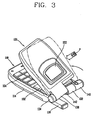
- the related art folder type mobile terminal has its problems. Because the camera 140 is mounted at the hinge connection part 130, the support area (L) of the hinge part 136 of the folder 120, as shown in Figure 2, is reduced. This is due to the hinge part 136's cantilever form design such that the hinge part 136 is eccentrically supported off-center at the upper end of the main body 110. As shown in Figure 3, if a user inadvertently drops the terminal so that an external force is applied to the terminal in the direction of an arrow 'P', the hinge part 136 is moved in a right direction (direction of the arrow 'P'). This movement is problematic because the hinge part 136 would then be released from the hinge protrusion 142 of the first support part 132.
- the folder 120 would be released from the main body 110. Additionally, if an external force is applied to the folder 120 in the left direction (direction opposite to the arrow 'P'), the folder 120 would be deformed, interfering with rotation of or damaging the camera 140.
- a folder type mobile terminal according to preamble of claim 1 is known from EP-A-1 267 576 .
- the hinge connection part of the mobile terminal disclosed in EP-A-1 267 576 consists of two hinge parts mounted at opposite outer sides of the lower end of the folder and of two support parts mounted at the upper end of the main body and located inwardly of the hinge parts.
- a camera unit is rotatably supported between the two support parts formed at the upper end of the main body and is thus located in the center of the hinge connection part.
- WO-A-02/090785 and US-A-2002/0168948 both disclose a folder type mobile terminal including a hinge connection part between a main body and a folder rotatably connected to the main body.
- the hinge connection includes two support parts formed at opposite outer side end portions of the upper end of the main body and further includes two hinge parts formed at the lower end of the folder inwardly of the two support parts.
- the folder type mobile terminals disclosed in WO-A-02/090785 and US-A-2002/0168948 do not include any camera unit.
- the present invention relates to a folder type mobile terminal capable of preventing separation of a folder from a main body when an external force is applied to the terminal.
- the present invention does so by improving a hinge structure of a hinge connection part between the folder and the main body to prevent movement of the folder in a horizontal or left/right direction.
- a folder type mobile terminal apparatus according to claim 1 and a method according to claim 14 is provided.
- the movement preventing part prevents movement of the folder in a horizontal direction.
- the hinge connection part comprises a first support part formed at an upper end of the main body, a second support part formed at an end portion of the upper end of the main body at a distance from the first support part, and a hinge part formed at a lower end of the folder and rotatably disposed between the first support part and the second support part.
- the movement preventing part is formed at a lower end of the folder at a distance from the hinge part, wherein the movement preventing part has a ring-like shape.
- the movement preventing part is also disposed between the camera unit and the first support part, wherein a hinge protrusion is formed at a side of the camera unit, the hinge protrusion being slidably inserted at an inner circumferential surface of the movement preventing part to rotatably support the movement preventing part.
- a space part is formed between the first support part and the camera unit so that the movement preventing part can be inserted in the space part, wherein the space part has a larger width than a width of the movement preventing part so that the movement preventing part can be inserted into the space part.
- a plug is mounted in the space part to cover a remaining space of the space part after the movement preventing part is inserted into the space part, wherein the plug prevents movement of the movement preventing part in a horizontal direction.
- the plug comprises a plug opening and at least one hooking jaw formed on at least one unbounded end of the plug for engaging the main body.
- the plug further comprises a first hooking protrusion formed at a side of the plug, the first hooking protrusion being engaged with a second hooking protrusion formed at a side of the first support part.
- a folder type mobile terminal has a main body and a folder rotatably connected to the main body, wherein a method for preventing movement of the folder in a horizontal direction, comprises inserting a hinge part formed at the folder into a first support part and a second support part formed at the main body, inserting a hinge protrusion of the first support part into a first side of the hinge part, hinge-connecting a second side of the hinge part by a second support part and a hinge module, inserting a movement preventing part formed at the folder into a space part formed at the main body, and inserting a plug into the space part to fill in a residual space not occupied by the movement preventing part.
- the space part is located between the first support part and a camera unit.
- the method further comprises inserting the camera unit into a side of the first support part, inserting a hinge protrusion of the camera unit into an inner surface of the movement preventing part, and mounting a stopper to a side of the main body so that the camera unit is rotatably supported at the first support part.
- a clamshell mobile communication terminal comprises a first body for housing a keypad, a second body for housing a display, and a hinge rotatably connecting a first side of the first body and a first side of the second body together, the hinge having a first pin for engaging the first and second bodies, along a cylindrical joint comprising hollow first and second support members.
- An inner surface of the first body is approximately tangent to a front surface of the second body in a closed position. The inner surface of the first body can rotate away from the front surface of the second body about a first axis to expose the inner surface of the first body and the front surface of the second body in an open position.
- the first side of the first body and the first side of the second body are connected along said first axis by way of the first pin penetrating the first and second support members of the cylindrical joint along the first axis.
- the first and second support members are spaced apart.
- a digital camera unit is mounted along said first axis juxtaposed to the second support member.
- the terminal further comprises a spacer ring mounted in between the first and second support members for tightly securing the first and second support members along the first axis.
- Figure 1 is a perspective view of a folder type mobile terminal in accordance with the related art.
- Figure 2 is an exploded perspective view of a main body and a folder of a folder type mobile terminal in accordance with the related art.
- Figure 3 is a perspective view of an external force being applied to a folder type mobile terminal in accordance with the related art.
- Figure 4 is a perspective view of a folder type mobile terminal in accordance with one embodiment of the invention.
- Figure 5 is an exploded perspective view of a folder and a main body of a folder type mobile terminal in accordance with one embodiment of the invention.
- Figure 6 is a sectional view of a hinge connection part of a folder type mobile terminal in accordance with one embodiment of the invention.
- Figure 7 is a perspective view of a folder in accordance with one embodiment of the invention.
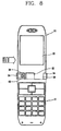
- Figure 8 is a front view of an external force being applied to a folder type mobile terminal in accordance with one embodiment of the invention.
- a folder type mobile terminal comprises a main body 10 having a printed circuit board (PCB) with various circuit components mounted thereon. Menu buttons 12 and dial buttons 14 are also mounted on the main body 10.
- the terminal further comprises a folder 20 rotatably connected to the main body 10.
- the folder includes a display device 22, such as a liquid crystal display (LCD), for displaying user information.
- a hinge connection part 30 is formed between the main body 10 and the folder 20 for rotatably connecting the folder 20 with the main body 10.
- a camera unit 24 may be rotatably mounted at the hinge connection part 30 to allow the user to take a photograph with the terminal.
- the main body 10 further comprises a battery 16 detachably attached at a rear surface of the main body to supply power to the terminal.
- An antenna 18 is mounted at an upper side of the main body to transmit and receive a communication signal.
- the hinge connection part 30 comprises a first support part 32 formed at the center of an upper end of the main body 10.
- a second support part 34 is formed at an end portion of the upper end of the main body 10 at a certain distance from the first support part 32.
- a hinge part 36 is formed at a lower end of the folder 20 rotatably disposed between the first support part 32 and the second support part 34.
- a hinge module 40 is inserted in the second support part 34 and the hinge part 36.
- a movement preventing part 38 is formed at a lower end of the folder 20 at a certain distance from the hinge part 36. The movement preventing part 38 serves to prevent movement of the folder 20, particularly to prevent movement in a horizontal or left/right direction.
- the first support part 32 may have a cylindrical form and is formed at the center of the upper end of the main body 10.
- the camera unit 24 is rotatably supported at one side of the first support part 32.
- a cylindrical hinge protrusion 50 is formed on the other side of the first support part 32.
- the hinge protrusion 50 preferably has a smaller diameter than the hinge part 36 so that it may be inserted into the hinge part 36.
- the second support part 34 has a fixed groove 52 in which the hinge module 40 is insertedly fixed.
- the hinge part 36 may have a cylindrical form and is preferably disposed to one side of the lower end of the folder 20.
- a first hinge part 54, into which the hinge module 40 can be rotatably inserted, is formed at one side of the hinge part 36.
- a second hinge part 56 is formed at the other side of the hinge part 36 and is rotatably inserted at an outer circumferential surface of the hinge protrusion 50 of the first support part 32.
- the movement preventing part 38 may have a cylindrical or ring-like shape and is preferably formed at a lower end of the folder 20 at a certain distance from the hinge part 36.
- the camera unit 24 is inserted in the movement preventing part 38 wherein the camera unit is rotatably supported.
- a space part 58 is formed between the first support part 32 and the camera unit 24, into which the movement preventing part 38 is inserted.
- a width (S) of the space part 58 is larger than a width (T) of the movement preventing part 38, thus allowing the movement preventing part to be placed within the space part.
- a plug 60 is used for filling in a remaining space of the space part 58 after the movement preventing part 38 is inserted therein.
- the plug 60 serves to prevent movement of the movement preventing part 38 in a horizontal or left/right direction.
- the plug 60 may also be mounted in the space part 58 to give the outer surface of the mobile terminal a more aesthetically pleasing appearance.
- the plug 60 may have an unbounded ring-like shape. At an opening of the plug, unbounded ends of the plug 60 may comprise hooking jaws 62 for insertedly coupling the plug 60 to the upper end of the main body 10. As shown in Figure 6, the plug 60 has a first hooking protrusion 76 formed at a side thereof. The first hooking protrusion 76 may be engaged to a second hooking protrusion 78 formed at a side of the first support part 32.
- a hinge protrusion 66 is formed at a side of the camera unit 24.
- the hinge protrusion 66 is slidably inserted at an inner circumferential surface of the movement preventing part 38 to rotatably support the movement preventing part 38.
- a stopper 70 is engaged so that the camera unit 24 can be rotatably supported at the first support part 32.
- the hinge part 36 formed at the folder 20 is inserted into the first support part 32 and the second support part 34 formed at the main body 10. Then, the hinge protrusion 50 of the first support part 32 is inserted into one side of the hinge part 36. The other side of the hinge part 36 is hinge-connected by the second support part 34 and the hinge module 40.
- the movement preventing part 38 of the folder 20 is inserted into the space part 58 between the first support part 32 and the camera unit 24.
- the space part 58 has a sufficient (residual) space, so that the movement preventing part 38 can be easily inserted therein.
- the hinge protrusion 66 of the camera 24 is inserted to the inner circumferential surface of the movement preventing part 38, so that the movement preventing part 38 can be rotatably supported.
- the plug 60 is inserted into the space part 58 to fill in the residual space, and the stopper 70 is mounted at one side of the main body 10 so that the camera unit 24 can be rotatably supported at the first support part 32.
- the folder type mobile terminal of the present invention has the following advantages. Because the movement preventing part 38 is formed at the folder 20 and rotatably supported between the first support part 32 of the main body 10 and the camera unit 24, even if a terminal is inadvertently dropped or an external force is applied in a side direction of the folder, as shown in Figure 8, the hinge part 36 of the folder is prevented from moving in the horizontal or left/right direction, thereby preventing the folder from being released from the main body.
Landscapes
- Engineering & Computer Science (AREA)
- Signal Processing (AREA)
- Human Computer Interaction (AREA)
- Computer Networks & Wireless Communication (AREA)
- Telephone Set Structure (AREA)
- Casings For Electric Apparatus (AREA)
- Transmitters (AREA)
- Pivots And Pivotal Connections (AREA)
Claims (16)
- Faltbares mobiles Endgerät, mit:- einem Hauptkörper (10),- einem drehbar mit dem Hauptkörper (10) verbundenen Klappdeckel (20),- einem Scharnierverbindungsteil (30), das zwischen dem Hauptkörper (10) und dem Klappdeckel (20) ausgebildet ist, um den Klappdeckel (20) drehbar mit dem Hauptkörper (10) zu verbinden, wobei das Scharnierverbindungsteil (30) ein an einem oberen Ende des Hauptkörpers (10) ausgebildetes erstes Halteteil (32), ein zweites Halteteil (34), das an einem ersten Seitenendabschnitt des oberen Endes des Hauptkörpers (10) in einem Abstand von dem ersten Halteteil (32) ausbildet ist, und ein Scharnierteil (36) aufweist, das an einem unteren Ende des Klappdeckels (20) ausgebildet und drehbar zwischen dem ersten Halteteil (32) und dem zweiten Halteteil (34) angeordnet ist,dadurch gekennzeichnet, dass es zusätzlich ein Bewegungsverhinderungsteil (38) aufweist, das am unteren Ende des Klappdeckels (20) in einem Abstand von dem Scharnierteil (36) ausgebildet ist, um eine Bewegung des Klappdeckels (20) von dem Hauptkörper (10) zu verhindern, und dass eine Kameraeinheit (24) drehbar an einer Seite des Scharnierverbindungsteils (30) entgegengesetzt dem ersten Seitenendabschnitt des oberen Endes des Hauptkörpers (10) angebracht ist, wobei ein Scharniervorsprung (66) der Kameraeinheit (24) in eine Innenfläche des Bewegungsverhinderungsteils (38) eingesetzt ist und das Bewegungsverhinderungsteil (38) die Kameraeinheit (24) drehbar abstützt.
- Endgerät nach Anspruch 1,
bei dem das Bewegungsverhinderungsteil (38) eine Bewegung des Klappdeckels (20) in einer horizontalen Richtung verhindert. - Endgerät nach Anspruch 1,
bei dem der Klappdeckel (20) eine auf ihm befestigte Anzeigeeinrichtung umfasst. - Endgerät nach Anspruch 1,
bei dem die Kameraeinheit (24) drehbar an einer Seite des ersten Halteteils (32) befestigt ist. - Endgerät nach Anspruch 1,
bei dem das Bewegungsverhinderungsteil (38) eine ringartige Gestalt hat. - Endgerät nach Anspruch 1,
bei dem das Bewegungsverhinderungsteil (38) zwischen der Kameraeinheit (24) und dem ersten Halteteil (32) angeordnet ist. - Endgerät nach Anspruch 1,
bei dem der Scharniervorsprung (66) an einer Seite der Kameraeinheit (24) ausgebildet ist, wobei der Scharniervorsprung gleitbeweglich an einer Innenumfangsfläche des Bewegungsverhinderungsteils (38) eingesetzt ist, um das Bewegungsverhinderungsteil (38) drehbar abzustützen. - Endgerät nach Anspruch 1,
bei dem das erste Halteteil (32) und die Kameraeinheit (24) durch einen Zwischenraum getrennt sind, wobei das Bewegungsverhinderungsteil (38) in den Zwischenraum einsetzt ist. - Endgerät nach Anspruch 8,
bei dem der Zwischenraum eine größere Breite (S) als eine Breite (T) des Bewegungsverhinderungsteils (38) hat, so dass das Bewegungsverhinderungsteil (38) in den Zwischenraum einsetzbar ist. - Endgerät nach Anspruch 9,
bei dem ein Stopfen (60) in dem Zwischenraum befestigt ist, um einen verbleibenden Bereich des Zwischenraums abzudecken, nachdem das Bewegungsverhinderungsteil (38) in den Zwischenraum einsetzt worden ist. - Endgerät nach Anspruch 10,
bei dem der Stopfen (60) eine Bewegung des Bewegungsverhinderungsteils (38) in einer horizontalen Richtung verhindert. - Endgerät nach Anspruch 10,
bei dem der Stopfen (60) eine Stopfenöffnung und wenigstens eine Einhängebacke (62) aufweist, die an wenigstens einem freien Ende des Stopfens (60) zum Eingriff mit dem Hauptkörper (10) ausgebildet ist. - Endgerät nach Anspruch 10,
bei dem der Stopfen (60) einen ersten an einer Seite des Stopfens (60) ausgebildeten Einhängevorsprung (76) aufweist, wobei der erste Einhängevorsprung (76) mit einem zweiten Einhängevorsprung (78) in Eingriff steht, der an einer Seite des ersten Halteteils (32) ausgebildet ist. - Verfahren, für ein faltbares mobiles Endgerät mit einem Hauptkörper (10) und einem drehbar mit dem Hauptkörper (10) verbundenen Klappdeckel (20), zum Verhindern einer Bewegung des Klappdeckels (20) in einer horizontalen Richtung, umfassend:- Einsetzen eines an einem unteren Ende des Klappdeckels (20) ausgebildeten Scharnierteils (36) in ein erstes, an einem oberen Ende des Hauptkörpers (10) ausgebildetes Halteteil (32) und ein an einem ersten Seitenendabschnitt des oberen Endes des Hauptkörpers (10) in einem Abstand von dem ersten Halteteil (32) ausgebildetes zweites Halteteil (34),- Einsetzen eines Scharniervorsprungs (50) des ersten Halteteils (32) in eine erste Seite des Scharnierteils (36),- Anlenken einer zweiten Seite des Scharnierteils (36) mittels eines zweiten Halteteils (34) und eines Scharniermoduls (40),- Einsetzen eines Bewegungsverhinderungsteils (38), das am unteren Ende des Klappdeckels (20) ausgebildet ist, in ein am Hauptkörper (10) ausgebildetes Zwischenraumteil (58),- Einsetzen eines Scharniervorsprungs (66) einer Kameraeinheit (24) in eine Innenfläche des Bewegungsverhinderungsteils (38), und- Einsetzen eines Stopfens (60) in das Zwischenraumteil (58), um einen von dem Bewegungsverhinderungsteil (38) nicht eingenommenen Restzwischenraum auszufüllen.
- Verfahren nach Anspruch 14,
bei dem das Zwischenraumteil (58) zwischen dem ersten Halteteil (32) und der Kameraeinheit (24) angeordnet ist. - Verfahren nach Anspruch 15,
ferner umfassend:- Einsetzen der Kameraeinheit (24) in eine Seite des ersten Halteteils (32), und- Befestigen eines Anschlags (70) an einer Seite des Hauptkörpers (10), so dass die Kameraeinheit (24) drehbar an dem ersten Halteteil (32) abgestützt ist.
Applications Claiming Priority (2)
| Application Number | Priority Date | Filing Date | Title |
|---|---|---|---|
| KR1020030075628A KR100575746B1 (ko) | 2003-10-28 | 2003-10-28 | 폴더형 휴대 단말기 |
| KR2003075628 | 2003-10-28 |
Publications (2)
| Publication Number | Publication Date |
|---|---|
| EP1528756A1 EP1528756A1 (de) | 2005-05-04 |
| EP1528756B1 true EP1528756B1 (de) | 2007-12-19 |
Family
ID=34420678
Family Applications (1)
| Application Number | Title | Priority Date | Filing Date |
|---|---|---|---|
| EP04025426A Expired - Lifetime EP1528756B1 (de) | 2003-10-28 | 2004-10-26 | Klappbares Kommunikationsgerät |
Country Status (7)
| Country | Link |
|---|---|
| US (1) | US7437185B2 (de) |
| EP (1) | EP1528756B1 (de) |
| JP (1) | JP2005136996A (de) |
| KR (1) | KR100575746B1 (de) |
| CN (1) | CN100588208C (de) |
| AT (1) | ATE381847T1 (de) |
| DE (1) | DE602004010772T2 (de) |
Families Citing this family (13)
| Publication number | Priority date | Publication date | Assignee | Title |
|---|---|---|---|---|
| US20030228884A1 (en) * | 2002-05-23 | 2003-12-11 | Hiroshi Iwai | Two folding mobile telephone and mobile telephone |
| US7089035B2 (en) * | 2003-10-28 | 2006-08-08 | Omron Corporation | Wireless operating system |
| KR100617688B1 (ko) * | 2004-05-19 | 2006-08-28 | 삼성전자주식회사 | 휴대 단말기의 힌지 장치 |
| KR100630068B1 (ko) * | 2005-01-25 | 2006-09-27 | 삼성전자주식회사 | 디스플레이 회전형 휴대 단말기의 힌지 장치 |
| KR100667531B1 (ko) * | 2005-03-09 | 2007-01-10 | 엘지전자 주식회사 | 폴더부의 흔들림이 방지되는 폴더형 휴대폰 |
| JP4541412B2 (ja) * | 2005-08-22 | 2010-09-08 | スガツネ工業株式会社 | ヒンジ装置 |
| US8186015B2 (en) * | 2005-09-29 | 2012-05-29 | Sony Mobile Communications Ab | Self-contained floating shaft hinge mechanism |
| USD567205S1 (en) * | 2006-02-10 | 2008-04-22 | Samsung Electronics Co., Ltd. | Portable phone with removable wireless earpiece |
| KR101007611B1 (ko) | 2006-03-17 | 2011-01-12 | 갤럭시아디바이스 주식회사 | 개인휴대단말기의 단자 결합구조 및 그 결합방법 |
| JP5114035B2 (ja) * | 2006-09-08 | 2013-01-09 | 日本電気株式会社 | ヒンジ構造及びこれを用いた折り畳み型携帯端末 |
| CN100510205C (zh) * | 2007-06-06 | 2009-07-08 | 中国科学院安徽光学精密机械研究所 | Yb掺杂的锗酸钆、锗酸镧及其熔体法生长方法 |
| CN103795827B (zh) * | 2013-08-16 | 2016-09-21 | 南昌欧菲光电技术有限公司 | 移动终端电路板组件及移动终端 |
| KR102664692B1 (ko) | 2019-08-08 | 2024-05-09 | 삼성전자주식회사 | 플렉시블 디스플레이 및 카메라를 포함하는 전자 장치 |
Family Cites Families (21)
| Publication number | Priority date | Publication date | Assignee | Title |
|---|---|---|---|---|
| JP3516328B2 (ja) * | 1997-08-22 | 2004-04-05 | 株式会社日立製作所 | 情報通信端末装置 |
| KR100274623B1 (ko) * | 1997-12-23 | 2000-12-15 | 윤종용 | 디지털 스틸 카메라 |
| JP3265572B2 (ja) * | 1998-11-20 | 2002-03-11 | 日本電気株式会社 | 折畳式携帯電話器の開閉装置 |
| KR100678082B1 (ko) * | 1998-12-30 | 2007-05-17 | 삼성전자주식회사 | 폴더 타입 휴대폰에서 메인 보드와 엘씨디 모듈간의연결장치 |
| KR20010068807A (ko) * | 2000-01-10 | 2001-07-23 | 윤종용 | 영상 통신용 무선 단말기 |
| JP3739641B2 (ja) * | 2000-04-19 | 2006-01-25 | 富士通株式会社 | 折りたたみ型携帯機 |
| JP3448547B2 (ja) * | 2000-05-12 | 2003-09-22 | 三洋電機株式会社 | 折り畳み式携帯電話機 |
| JP4637332B2 (ja) * | 2000-08-04 | 2011-02-23 | パナソニック株式会社 | 折り畳み式携帯無線装置 |
| JP2002290523A (ja) | 2001-03-22 | 2002-10-04 | Minolta Co Ltd | カメラ付き折畳式携帯機器 |
| JP3643787B2 (ja) * | 2001-05-09 | 2005-04-27 | 三洋電機株式会社 | 折畳み式携帯端末機器 |
| JP5036103B2 (ja) * | 2001-05-14 | 2012-09-26 | 日本電気株式会社 | 携帯用通信機 |
| JP3483144B2 (ja) | 2001-05-31 | 2004-01-06 | 松下電器産業株式会社 | カメラ付き携帯端末装置 |
| KR100539527B1 (ko) * | 2001-06-12 | 2005-12-29 | 엘지전자 주식회사 | 카메라를 구비한 휴대전화기 |
| JP4578727B2 (ja) * | 2001-06-19 | 2010-11-10 | パナソニック株式会社 | 回動機能付きカメラを備えた情報端末装置 |
| KR100449451B1 (ko) * | 2001-12-08 | 2004-09-21 | 삼성전자주식회사 | 휴대폰의 카메라 렌즈 장착 장치 |
| KR100672095B1 (ko) * | 2002-06-26 | 2007-01-19 | 교세라 가부시키가이샤 | 촬상 기능을 구비한 휴대 단말 장치 |
| KR100474292B1 (ko) * | 2002-07-02 | 2005-03-10 | 엘지전자 주식회사 | 이동 단말기의 폴더 |
| KR100469361B1 (ko) * | 2002-07-24 | 2005-01-31 | 삼성전기주식회사 | 휴대전화기의 폴더 구동장치 |
| JP4071568B2 (ja) * | 2002-07-30 | 2008-04-02 | シャープ株式会社 | 携帯機器 |
| JP2004120670A (ja) * | 2002-09-30 | 2004-04-15 | Hitachi Ltd | 折畳み式携帯端末装置 |
| KR100480434B1 (ko) * | 2002-11-13 | 2005-04-07 | 삼성전자주식회사 | 카메라 렌즈 어셈블리 및 그를 구비하는 휴대용 무선 단말기 |
-
2003
- 2003-10-28 KR KR1020030075628A patent/KR100575746B1/ko not_active Expired - Fee Related
-
2004
- 2004-10-26 EP EP04025426A patent/EP1528756B1/de not_active Expired - Lifetime
- 2004-10-26 DE DE602004010772T patent/DE602004010772T2/de not_active Expired - Lifetime
- 2004-10-26 AT AT04025426T patent/ATE381847T1/de not_active IP Right Cessation
- 2004-10-27 JP JP2004313156A patent/JP2005136996A/ja active Pending
- 2004-10-27 US US10/975,939 patent/US7437185B2/en not_active Expired - Fee Related
- 2004-10-28 CN CN200410089630A patent/CN100588208C/zh not_active Expired - Fee Related
Also Published As
| Publication number | Publication date |
|---|---|
| CN1612576A (zh) | 2005-05-04 |
| CN100588208C (zh) | 2010-02-03 |
| DE602004010772T2 (de) | 2008-12-24 |
| DE602004010772D1 (de) | 2008-01-31 |
| KR100575746B1 (ko) | 2006-05-03 |
| JP2005136996A (ja) | 2005-05-26 |
| EP1528756A1 (de) | 2005-05-04 |
| ATE381847T1 (de) | 2008-01-15 |
| US20050090297A1 (en) | 2005-04-28 |
| KR20050040433A (ko) | 2005-05-03 |
| US7437185B2 (en) | 2008-10-14 |
Similar Documents
| Publication | Publication Date | Title |
|---|---|---|
| EP1530346B1 (de) | Handy mit schwenkbarer Anzeigevorrichtung | |
| EP1528756B1 (de) | Klappbares Kommunikationsgerät | |
| EP1381207B1 (de) | Mobiles Endgerät mit drehbar gelagertem Kameraobjektiv | |
| US7212845B2 (en) | Portable terminal device capable of displaying information in a closed state | |
| EP1630331B1 (de) | Biaxiales Scharnier für tragbaren Geräte und Montagevorrichtung | |
| EP1553748A2 (de) | Tragbares kabelloses Endgerät mit einer zusätzlichen drehbaren Anzeige | |
| KR100664184B1 (ko) | 듀얼힌지장치 및 이를 구비한 이동통신 단말기 | |
| EP1684491A2 (de) | Scharniervorrichtung für ein Mobilendgerät | |
| JPH10155013A (ja) | 携帯通信機 | |
| KR100630127B1 (ko) | 보조 표시부를 구비한 폴더 타입 무선 단말기 및 보조표시부 구동방법 | |
| KR100663553B1 (ko) | 카메라 렌즈 어셈블리를 구비하는 휴대용 단말기 | |
| KR20080011574A (ko) | 와치 타입 휴대용 단말기 | |
| KR20090006372A (ko) | 다기능 커버를 구비한 휴대용 전자 기기 | |
| KR200174762Y1 (ko) | 휴대폰의 카메라 렌즈 장착장치 | |
| KR100542950B1 (ko) | 휴대폰의 회전식 카메라용 고정장치 | |
| KR20020078373A (ko) | 삼중 폴더형 단말기 | |
| KR100469421B1 (ko) | 휴대용 단말기의 로고회전장치 | |
| KR200369496Y1 (ko) | 휴대 단말기의 연성회로 고정 장치 | |
| KR100995029B1 (ko) | 이동통신 단말기의 카메라 회동장치 | |
| JP2003258973A (ja) | 携帯通信端末装置 | |
| KR100318923B1 (ko) | 복합 휴대용 무선단말기의 지피에스 안테나 장치 | |
| KR200241098Y1 (ko) | 폴더형 이동통신 단말기 | |
| KR20050021097A (ko) | 수평 회전형 휴대용 단말기 | |
| KR100434455B1 (ko) | 이중 힌지 장치를 구비한 플립이 제공된 휴대폰 | |
| KR20060036015A (ko) | 이동통신단말기의 내장형 안테나 장치 |
Legal Events
| Date | Code | Title | Description |
|---|---|---|---|
| PUAI | Public reference made under article 153(3) epc to a published international application that has entered the european phase |
Free format text: ORIGINAL CODE: 0009012 |
|
| 17P | Request for examination filed |
Effective date: 20041026 |
|
| AK | Designated contracting states |
Kind code of ref document: A1 Designated state(s): AT BE BG CH CY CZ DE DK EE ES FI FR GB GR HU IE IT LI LU MC NL PL PT RO SE SI SK TR |
|
| AX | Request for extension of the european patent |
Extension state: AL HR LT LV MK |
|
| AKX | Designation fees paid |
Designated state(s): AT BE BG CH CY CZ DE DK EE ES FI FR GB GR HU IE IT LI LU MC NL PL PT RO SE SI SK TR |
|
| 17Q | First examination report despatched |
Effective date: 20060307 |
|
| GRAP | Despatch of communication of intention to grant a patent |
Free format text: ORIGINAL CODE: EPIDOSNIGR1 |
|
| GRAJ | Information related to disapproval of communication of intention to grant by the applicant or resumption of examination proceedings by the epo deleted |
Free format text: ORIGINAL CODE: EPIDOSDIGR1 |
|
| GRAP | Despatch of communication of intention to grant a patent |
Free format text: ORIGINAL CODE: EPIDOSNIGR1 |
|
| GRAS | Grant fee paid |
Free format text: ORIGINAL CODE: EPIDOSNIGR3 |
|
| GRAA | (expected) grant |
Free format text: ORIGINAL CODE: 0009210 |
|
| AK | Designated contracting states |
Kind code of ref document: B1 Designated state(s): AT BE BG CH CY CZ DE DK EE ES FI FR GB GR HU IE IT LI LU MC NL PL PT RO SE SI SK TR |
|
| REG | Reference to a national code |
Ref country code: GB Ref legal event code: FG4D |
|
| REG | Reference to a national code |
Ref country code: IE Ref legal event code: FG4D |
|
| REG | Reference to a national code |
Ref country code: CH Ref legal event code: EP |
|
| REF | Corresponds to: |
Ref document number: 602004010772 Country of ref document: DE Date of ref document: 20080131 Kind code of ref document: P |
|
| REG | Reference to a national code |
Ref country code: SE Ref legal event code: TRGR |
|
| PG25 | Lapsed in a contracting state [announced via postgrant information from national office to epo] |
Ref country code: CH Free format text: LAPSE BECAUSE OF FAILURE TO SUBMIT A TRANSLATION OF THE DESCRIPTION OR TO PAY THE FEE WITHIN THE PRESCRIBED TIME-LIMIT Effective date: 20071219 Ref country code: LI Free format text: LAPSE BECAUSE OF FAILURE TO SUBMIT A TRANSLATION OF THE DESCRIPTION OR TO PAY THE FEE WITHIN THE PRESCRIBED TIME-LIMIT Effective date: 20071219 |
|
| PG25 | Lapsed in a contracting state [announced via postgrant information from national office to epo] |
Ref country code: PL Free format text: LAPSE BECAUSE OF FAILURE TO SUBMIT A TRANSLATION OF THE DESCRIPTION OR TO PAY THE FEE WITHIN THE PRESCRIBED TIME-LIMIT Effective date: 20071219 Ref country code: SI Free format text: LAPSE BECAUSE OF FAILURE TO SUBMIT A TRANSLATION OF THE DESCRIPTION OR TO PAY THE FEE WITHIN THE PRESCRIBED TIME-LIMIT Effective date: 20071219 |
|
| REG | Reference to a national code |
Ref country code: CH Ref legal event code: PL |
|
| PG25 | Lapsed in a contracting state [announced via postgrant information from national office to epo] |
Ref country code: AT Free format text: LAPSE BECAUSE OF FAILURE TO SUBMIT A TRANSLATION OF THE DESCRIPTION OR TO PAY THE FEE WITHIN THE PRESCRIBED TIME-LIMIT Effective date: 20071219 |
|
| PG25 | Lapsed in a contracting state [announced via postgrant information from national office to epo] |
Ref country code: CZ Free format text: LAPSE BECAUSE OF FAILURE TO SUBMIT A TRANSLATION OF THE DESCRIPTION OR TO PAY THE FEE WITHIN THE PRESCRIBED TIME-LIMIT Effective date: 20071219 Ref country code: ES Free format text: LAPSE BECAUSE OF FAILURE TO SUBMIT A TRANSLATION OF THE DESCRIPTION OR TO PAY THE FEE WITHIN THE PRESCRIBED TIME-LIMIT Effective date: 20080330 |
|
| ET | Fr: translation filed | ||
| PG25 | Lapsed in a contracting state [announced via postgrant information from national office to epo] |
Ref country code: RO Free format text: LAPSE BECAUSE OF FAILURE TO SUBMIT A TRANSLATION OF THE DESCRIPTION OR TO PAY THE FEE WITHIN THE PRESCRIBED TIME-LIMIT Effective date: 20071219 Ref country code: BE Free format text: LAPSE BECAUSE OF FAILURE TO SUBMIT A TRANSLATION OF THE DESCRIPTION OR TO PAY THE FEE WITHIN THE PRESCRIBED TIME-LIMIT Effective date: 20071219 Ref country code: SK Free format text: LAPSE BECAUSE OF FAILURE TO SUBMIT A TRANSLATION OF THE DESCRIPTION OR TO PAY THE FEE WITHIN THE PRESCRIBED TIME-LIMIT Effective date: 20071219 |
|
| PG25 | Lapsed in a contracting state [announced via postgrant information from national office to epo] |
Ref country code: PT Free format text: LAPSE BECAUSE OF FAILURE TO SUBMIT A TRANSLATION OF THE DESCRIPTION OR TO PAY THE FEE WITHIN THE PRESCRIBED TIME-LIMIT Effective date: 20080519 |
|
| PLBE | No opposition filed within time limit |
Free format text: ORIGINAL CODE: 0009261 |
|
| STAA | Information on the status of an ep patent application or granted ep patent |
Free format text: STATUS: NO OPPOSITION FILED WITHIN TIME LIMIT |
|
| PG25 | Lapsed in a contracting state [announced via postgrant information from national office to epo] |
Ref country code: DK Free format text: LAPSE BECAUSE OF FAILURE TO SUBMIT A TRANSLATION OF THE DESCRIPTION OR TO PAY THE FEE WITHIN THE PRESCRIBED TIME-LIMIT Effective date: 20071219 |
|
| 26N | No opposition filed |
Effective date: 20080922 |
|
| PG25 | Lapsed in a contracting state [announced via postgrant information from national office to epo] |
Ref country code: GR Free format text: LAPSE BECAUSE OF FAILURE TO SUBMIT A TRANSLATION OF THE DESCRIPTION OR TO PAY THE FEE WITHIN THE PRESCRIBED TIME-LIMIT Effective date: 20080320 |
|
| PG25 | Lapsed in a contracting state [announced via postgrant information from national office to epo] |
Ref country code: EE Free format text: LAPSE BECAUSE OF FAILURE TO SUBMIT A TRANSLATION OF THE DESCRIPTION OR TO PAY THE FEE WITHIN THE PRESCRIBED TIME-LIMIT Effective date: 20071219 Ref country code: BG Free format text: LAPSE BECAUSE OF FAILURE TO SUBMIT A TRANSLATION OF THE DESCRIPTION OR TO PAY THE FEE WITHIN THE PRESCRIBED TIME-LIMIT Effective date: 20080319 |
|
| PG25 | Lapsed in a contracting state [announced via postgrant information from national office to epo] |
Ref country code: MC Free format text: LAPSE BECAUSE OF NON-PAYMENT OF DUE FEES Effective date: 20081031 |
|
| PG25 | Lapsed in a contracting state [announced via postgrant information from national office to epo] |
Ref country code: CY Free format text: LAPSE BECAUSE OF FAILURE TO SUBMIT A TRANSLATION OF THE DESCRIPTION OR TO PAY THE FEE WITHIN THE PRESCRIBED TIME-LIMIT Effective date: 20071219 |
|
| PG25 | Lapsed in a contracting state [announced via postgrant information from national office to epo] |
Ref country code: IE Free format text: LAPSE BECAUSE OF NON-PAYMENT OF DUE FEES Effective date: 20081027 |
|
| PG25 | Lapsed in a contracting state [announced via postgrant information from national office to epo] |
Ref country code: HU Free format text: LAPSE BECAUSE OF FAILURE TO SUBMIT A TRANSLATION OF THE DESCRIPTION OR TO PAY THE FEE WITHIN THE PRESCRIBED TIME-LIMIT Effective date: 20080620 Ref country code: LU Free format text: LAPSE BECAUSE OF NON-PAYMENT OF DUE FEES Effective date: 20081026 |
|
| PG25 | Lapsed in a contracting state [announced via postgrant information from national office to epo] |
Ref country code: TR Free format text: LAPSE BECAUSE OF FAILURE TO SUBMIT A TRANSLATION OF THE DESCRIPTION OR TO PAY THE FEE WITHIN THE PRESCRIBED TIME-LIMIT Effective date: 20071219 |
|
| REG | Reference to a national code |
Ref country code: FR Ref legal event code: PLFP Year of fee payment: 12 |
|
| PGFP | Annual fee paid to national office [announced via postgrant information from national office to epo] |
Ref country code: GB Payment date: 20150911 Year of fee payment: 12 Ref country code: FI Payment date: 20150911 Year of fee payment: 12 |
|
| PGFP | Annual fee paid to national office [announced via postgrant information from national office to epo] |
Ref country code: SE Payment date: 20150911 Year of fee payment: 12 Ref country code: FR Payment date: 20150915 Year of fee payment: 12 |
|
| PGFP | Annual fee paid to national office [announced via postgrant information from national office to epo] |
Ref country code: DE Payment date: 20150911 Year of fee payment: 12 Ref country code: IT Payment date: 20151014 Year of fee payment: 12 |
|
| PGFP | Annual fee paid to national office [announced via postgrant information from national office to epo] |
Ref country code: NL Payment date: 20150911 Year of fee payment: 12 |
|
| REG | Reference to a national code |
Ref country code: DE Ref legal event code: R119 Ref document number: 602004010772 Country of ref document: DE |
|
| REG | Reference to a national code |
Ref country code: NL Ref legal event code: MM Effective date: 20161101 |
|
| GBPC | Gb: european patent ceased through non-payment of renewal fee |
Effective date: 20161026 |
|
| REG | Reference to a national code |
Ref country code: FR Ref legal event code: ST Effective date: 20170630 |
|
| PG25 | Lapsed in a contracting state [announced via postgrant information from national office to epo] |
Ref country code: GB Free format text: LAPSE BECAUSE OF NON-PAYMENT OF DUE FEES Effective date: 20161026 Ref country code: FR Free format text: LAPSE BECAUSE OF NON-PAYMENT OF DUE FEES Effective date: 20161102 Ref country code: FI Free format text: LAPSE BECAUSE OF NON-PAYMENT OF DUE FEES Effective date: 20161026 Ref country code: DE Free format text: LAPSE BECAUSE OF NON-PAYMENT OF DUE FEES Effective date: 20170503 |
|
| PG25 | Lapsed in a contracting state [announced via postgrant information from national office to epo] |
Ref country code: SE Free format text: LAPSE BECAUSE OF NON-PAYMENT OF DUE FEES Effective date: 20161027 Ref country code: NL Free format text: LAPSE BECAUSE OF NON-PAYMENT OF DUE FEES Effective date: 20161101 |
|
| PG25 | Lapsed in a contracting state [announced via postgrant information from national office to epo] |
Ref country code: IT Free format text: LAPSE BECAUSE OF NON-PAYMENT OF DUE FEES Effective date: 20161026 |