EP1528783A1 - Verfahren und Gerät für Energieversorgung in einem drahtgebundenen Telekommunikationssystem - Google Patents
Verfahren und Gerät für Energieversorgung in einem drahtgebundenen Telekommunikationssystem Download PDFInfo
- Publication number
- EP1528783A1 EP1528783A1 EP03447287A EP03447287A EP1528783A1 EP 1528783 A1 EP1528783 A1 EP 1528783A1 EP 03447287 A EP03447287 A EP 03447287A EP 03447287 A EP03447287 A EP 03447287A EP 1528783 A1 EP1528783 A1 EP 1528783A1
- Authority
- EP
- European Patent Office
- Prior art keywords
- satellite
- converter
- main
- power supply
- source
- Prior art date
- Legal status (The legal status is an assumption and is not a legal conclusion. Google has not performed a legal analysis and makes no representation as to the accuracy of the status listed.)
- Withdrawn
Links
- 238000000034 method Methods 0.000 title claims abstract description 5
- 230000005540 biological transmission Effects 0.000 claims abstract 2
- 238000012423 maintenance Methods 0.000 description 3
- 238000012360 testing method Methods 0.000 description 2
- 101000836649 Homo sapiens Selenoprotein V Proteins 0.000 description 1
- 102100027056 Selenoprotein V Human genes 0.000 description 1
- 241001080024 Telles Species 0.000 description 1
- 238000006243 chemical reaction Methods 0.000 description 1
- 238000010276 construction Methods 0.000 description 1
- 230000001419 dependent effect Effects 0.000 description 1
- 238000013461 design Methods 0.000 description 1
- 230000037213 diet Effects 0.000 description 1
- 235000005911 diet Nutrition 0.000 description 1
- 238000004146 energy storage Methods 0.000 description 1
- 239000000446 fuel Substances 0.000 description 1
- 238000002955 isolation Methods 0.000 description 1
- 238000013021 overheating Methods 0.000 description 1
- 230000000284 resting effect Effects 0.000 description 1
- 238000011144 upstream manufacturing Methods 0.000 description 1
- 238000012795 verification Methods 0.000 description 1
Images

Classifications
-
- H—ELECTRICITY
- H04—ELECTRIC COMMUNICATION TECHNIQUE
- H04M—TELEPHONIC COMMUNICATION
- H04M19/00—Current supply arrangements for telephone systems
- H04M19/08—Current supply arrangements for telephone systems with current supply sources at the substations
Definitions
- the present invention relates to a device power supply for telecommunication wire system, comprising a main converter, arranged to be connected to a source of main energy and to provide a main voltage to power a satellite unit of the telecommunication system; a source of energy backup power supply, connected to the satellite unit and arranged at provide auxiliary voltage to the satellite unit in case of non-compliance from the main voltage to at least one predetermined criterion.
- the auxiliary power source consists of energy storage elements, for example batteries directly connected to the satellite unit. This generates costs investment in infrastructure and high maintenance costs. In in addition, these local systems are cumbersome.
- An object of the present invention is to mitigate at least one of these disadvantages.
- the device is characterized in that the auxiliary energy source comprises a central module having an input arranged to be connected to a source of energy available at the central office, and an output arranged to be connected to at least one pair of wires (TP), said pair of wires being connected to the satellite unit.
- TP wires
- the remote power system as a source of auxiliary energy, not only is it possible to obtain higher, but also at a lower cost than the systems local power supplies (with batteries) or remote power systems in main source used until today.
- the main source remote supply systems it is possible to reduce the number of pairs, including increasing the current maximum per pair, since losses are generated only by Occasional way when using in rescue mode.
- the invention also relates to a method of power supply for a telecommunication wire system, as well as the use of the remote power system as an auxiliary power source.
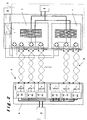
- the satellite unit 3 comprises the satellite converters 7, charge 6, and where applicable, the main converter 1. Each satellite converter may, where appropriate, be replaced by several converters in parallel.
- the central module 4 and the source of energy available at the central station 9 constitute the auxiliary energy source 2.
- the current charged by the remote power supply in normal conditions, is almost zero. If the local AC power disappears the remote power supply serves as backup and has a battery life (eg 48V) for several hours.
- the criterion predetermined indicating the non-compliance of the main voltage consists in the non-existence of a tension.
- the conformity of the predetermined criterion is to fall into a voltage range of example +/- 20% around the nominal voltage.
- the converter Principal 1 may integrate this conformity check function with the predetermined criterion.
- the control of compliance with the predetermined criterion would consist of the verification of the temperature of the main converter in a given range.
- Another advantage of the system according to the invention is that it simplifies the main converter and reduces its power nominal.
- the main converter 1 compared to a local food system Classically including batteries as an auxiliary power source, the main converter 1 must be oversized to ensure the possible recharging of the batteries while feeding the load.
- the main converter in conventional systems must in this case integrate battery management functions, such as the control of autonomy, temperature compensation, equalization ("boost mode ”) battery sub-elements, ...
- batteries at the local level are not necessary because the auxiliary power supply is provided by the remote power supply.
- the main converter 1 according to the invention should therefore not be equipped with these battery management functions.
- redundancy of N + x type where N is the number of power base units necessary to feed the load and x being backup units in case of default of one of the N base units.
- a remote power supply redundancy 3 + 1 includes three power supply units as well as a backup unit.
- An advantageous way to implement the system is to design the main converter in the same form and dimensions than a satellite converter. This allows easily transform a known system of conventional tele-power in the system according to the invention by replacing the satellite converter redundant by the main converter.
- the converter principal 1 is part of the satellite unit 3.
- the redundant power supply (3 + 1) it is also advantageous to provide the power of the main power equal to three times the power of a satellite converter.
- Another consequence of using remote power as an auxiliary source is to enable the implementation of parallel of the outputs of the central converters by limiting the disadvantages due to the increase in the maximum current of the series of central converters.
- An example of the inconvenience of Parallel Central Converters in Remote Power Systems used as the main source is dissipation excessive energy due to the larger current in the wire pair.
- the remote power supply is used only in emergency mode, in other words exceptionally. The dissipation of energy is therefore exceptional. This explains in part the efficiency gain of the system according to the invention.
- the lifespan of the whole chain is increased (by a factor four to five) because in normal feeding mode the load is powered by the main converter without going through the remote power supply relief, and in particular without going through the satellite converters. The maintenance costs are therefore greatly reduced.
- the main converter 1 preferably comprises means of testing the emergency power supply. For this purpose, the output voltage of the main converter to a lower value to that of the output voltage under load (for example 48 V) satellite converters for a short period of time (from a few seconds) and simultaneously the main converter checks that its output current is almost zero, in order to check the correct operation of the remote power supply.
- This test could be programmed automatically with a fixed cycle of, for example, one (1) week for a duration of one (1) minute.
- a second form would be to use diet differently, that is to say power the satellite converters 7 at the input, on the twisted pair side, with a higher voltage (for example +/- 180V) to that coming from the central converters (+/- 160V), through an additional diode bridge.
- a very form simple of the main converter 1 would be to use a transformer of 50/60 Hz voltage having a peak-to-peak secondary voltage of 360 V AC. In practice this embodiment would only work with very stable electrical networks.
- a variant of this last montage would be that the local power supply would have as many isolated +/- 180V outputs as tele-power supplies (RPB), so that all RPBs remain well independent.
- RPB tele-power supplies
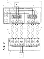
- Figure 3 shows a shape according to Figure 1 improved at the performance level by adding a local auxiliary power supply supplying the auxiliary circuits of the RPBs, the main source of resting consumption. It has the advantage of not having to be in compliance with the constraints of the RFT circuits in the event of a bridge failure diode, but should have (galvanic) isolation between the output of the main converter and the input of the satellite converter. This supply voltage is low (SELV) compared to the shape according to the figure 2.
- the remote power system can be if necessary that described in European Patent Application No. 03391001.9, the content is incorporated by reference, as well as that described in the European Patent Application No. 02077059.0.
Landscapes
- Engineering & Computer Science (AREA)
- Signal Processing (AREA)
- Direct Current Feeding And Distribution (AREA)
Applications Claiming Priority (2)
| Application Number | Priority Date | Filing Date | Title |
|---|---|---|---|
| BE200300589 | 2003-11-03 | ||
| BE200300589 | 2003-11-03 |
Publications (1)
| Publication Number | Publication Date |
|---|---|
| EP1528783A1 true EP1528783A1 (de) | 2005-05-04 |
Family
ID=34397929
Family Applications (1)
| Application Number | Title | Priority Date | Filing Date |
|---|---|---|---|
| EP03447287A Withdrawn EP1528783A1 (de) | 2003-11-03 | 2003-12-10 | Verfahren und Gerät für Energieversorgung in einem drahtgebundenen Telekommunikationssystem |
Country Status (1)
| Country | Link |
|---|---|
| EP (1) | EP1528783A1 (de) |
Citations (7)
| Publication number | Priority date | Publication date | Assignee | Title |
|---|---|---|---|---|
| EP0936798A1 (de) * | 1998-02-11 | 1999-08-18 | Sagem Sa | Faksimilegerät mit Notstromversorgung für Verbindungsmitteln |
| EP1161074A1 (de) * | 2000-05-30 | 2001-12-05 | Sagem S.A. | Verfahren zur sicherung einer telefonverbindung |
| EP1176792A1 (de) * | 2000-07-24 | 2002-01-30 | Alcatel | Verfahren und Vorrichtung zur optimierte Leistungsversorgung in einem digitalen Übertragungssystem |
| EP1189422A2 (de) * | 2000-08-29 | 2002-03-20 | Lucent Technologies Inc. | Vorrichtung und Verfahren zur Bereitstellung von Leistungsnotdiensten für DSL-Teilnehmern |
| US20020042229A1 (en) * | 2000-10-05 | 2002-04-11 | Alcatel | Terminal adapted to be powered locally and to receive a remote power feed via a link connecting it to a local area network |
| US20020130641A1 (en) * | 2001-03-09 | 2002-09-19 | Schofield Wade S. | Apparatus and method for providing span power to communication equipment at a customer premise |
| US6577882B1 (en) * | 1999-09-24 | 2003-06-10 | Telefonaktiebolaget Lm Ericsson | Arrangement and a method relating to power supply in a communications network |
-
2003
- 2003-12-10 EP EP03447287A patent/EP1528783A1/de not_active Withdrawn
Patent Citations (7)
| Publication number | Priority date | Publication date | Assignee | Title |
|---|---|---|---|---|
| EP0936798A1 (de) * | 1998-02-11 | 1999-08-18 | Sagem Sa | Faksimilegerät mit Notstromversorgung für Verbindungsmitteln |
| US6577882B1 (en) * | 1999-09-24 | 2003-06-10 | Telefonaktiebolaget Lm Ericsson | Arrangement and a method relating to power supply in a communications network |
| EP1161074A1 (de) * | 2000-05-30 | 2001-12-05 | Sagem S.A. | Verfahren zur sicherung einer telefonverbindung |
| EP1176792A1 (de) * | 2000-07-24 | 2002-01-30 | Alcatel | Verfahren und Vorrichtung zur optimierte Leistungsversorgung in einem digitalen Übertragungssystem |
| EP1189422A2 (de) * | 2000-08-29 | 2002-03-20 | Lucent Technologies Inc. | Vorrichtung und Verfahren zur Bereitstellung von Leistungsnotdiensten für DSL-Teilnehmern |
| US20020042229A1 (en) * | 2000-10-05 | 2002-04-11 | Alcatel | Terminal adapted to be powered locally and to receive a remote power feed via a link connecting it to a local area network |
| US20020130641A1 (en) * | 2001-03-09 | 2002-09-19 | Schofield Wade S. | Apparatus and method for providing span power to communication equipment at a customer premise |
Similar Documents
| Publication | Publication Date | Title |
|---|---|---|
| EP0578531B1 (de) | Unterbrechnungsfreie Stromversorgung mit verteiltem Speichersystem | |
| EP0734111B1 (de) | Photovoltaische Hochspannungsanlage mit individuellen Speichermitteln | |
| EP2820920B1 (de) | Intelligente tragbare beleuchtungsvorrichtung | |
| FR2784517A1 (fr) | Circuit d'alimentation en energie pour un reseau de bord de vehicule automobile a deux branches d'alimentation de tensions differentes | |
| EP2416468A2 (de) | Batterieausgleichsverfahren und Steuerungssystem dafür | |
| FR2972581A1 (fr) | Systeme d'equilibrage de charge pour batteries | |
| FR2713028A1 (fr) | Dispositif et procédé destinés à déterminer le type d'alimentation externe. | |
| EP2783443A1 (de) | Gesichertes und geregeltes kontinuierliches stromversorgungssystem mit mehreren eingängen | |
| FR2976745A1 (fr) | Mecanisme de commande securise pour systeme photovoltaique distribue | |
| FR2715779A3 (fr) | Système de commande de charge de batterie. | |
| FR3053851A1 (fr) | Dispositif de commande d'un systeme d'alimentation pour vehicule a couplage pile a combustible/batteries | |
| EP0035727B1 (de) | Energieversorgungssystem für elektronische Anlagen | |
| EP1815576B1 (de) | Autonomes elektrisches ladegerät | |
| EP2951904A1 (de) | Verfahren und system zur versorgung eines flugzeugs mit elektrischer energie | |
| CA2320871C (fr) | Systeme d'alimentation electrique permettant de simplifier l'architecture des installations d'energie et de climatisation | |
| CH699964A2 (fr) | Systeme d'alimentation electrique a cellules solaires incorporees pour machine de vente automatique. | |
| EP3465861B1 (de) | Verfahren zur stromversorgung einer vorrichtung durch eine autonome hybride station | |
| EP1528783A1 (de) | Verfahren und Gerät für Energieversorgung in einem drahtgebundenen Telekommunikationssystem | |
| WO2012028572A1 (fr) | Procede de charge d'une batterie electrique | |
| WO2025046181A1 (fr) | Dispositif d'alimentation sans interruption pour deux charges de niveaux de criticite differentes | |
| EP1040731B1 (de) | Speiseschaltung eines leuchtkastens | |
| FR2631753A1 (fr) | Regulateur de charge de batterie d'accumulateurs pour generateur photovoltaique | |
| EP1519467B1 (de) | Stromversorgung einer Einrichtung und Stromversorgungssystem für Einrichtung | |
| CA2605800A1 (fr) | Circuit d'alimentation sans interruption | |
| EP1177673B1 (de) | Telefonleitungsgespeistes stromversorgungssystem |
Legal Events
| Date | Code | Title | Description |
|---|---|---|---|
| PUAI | Public reference made under article 153(3) epc to a published international application that has entered the european phase |
Free format text: ORIGINAL CODE: 0009012 |
|
| AK | Designated contracting states |
Kind code of ref document: A1 Designated state(s): AT BE BG CH CY CZ DE DK EE ES FI FR GB GR HU IE IT LI LU MC NL PT RO SE SI SK TR |
|
| AX | Request for extension of the european patent |
Extension state: AL LT LV MK |
|
| 17P | Request for examination filed |
Effective date: 20051019 |
|
| AKX | Designation fees paid |
Designated state(s): AT BE BG CH CY CZ DE DK EE ES FI FR GB GR HU IE IT LI LU MC NL PT RO SE SI SK TR |
|
| STAA | Information on the status of an ep patent application or granted ep patent |
Free format text: STATUS: THE APPLICATION IS DEEMED TO BE WITHDRAWN |
|
| 18D | Application deemed to be withdrawn |
Effective date: 20060824 |