EP1529176B1 - Vorrichtung zum antrieb für doppelsitzventile - Google Patents
Vorrichtung zum antrieb für doppelsitzventile Download PDFInfo
- Publication number
- EP1529176B1 EP1529176B1 EP03793611A EP03793611A EP1529176B1 EP 1529176 B1 EP1529176 B1 EP 1529176B1 EP 03793611 A EP03793611 A EP 03793611A EP 03793611 A EP03793611 A EP 03793611A EP 1529176 B1 EP1529176 B1 EP 1529176B1
- Authority
- EP
- European Patent Office
- Prior art keywords
- piston
- housing
- open position
- pressurizing medium
- drive
- Prior art date
- Legal status (The legal status is an assumption and is not a legal conclusion. Google has not performed a legal analysis and makes no representation as to the accuracy of the status listed.)
- Expired - Lifetime
Links
- 230000000295 complement effect Effects 0.000 claims description 4
- 238000006073 displacement reaction Methods 0.000 claims description 3
- 238000005260 corrosion Methods 0.000 claims description 2
- 230000007797 corrosion Effects 0.000 claims description 2
- 229910001234 light alloy Inorganic materials 0.000 claims 1
- 239000013589 supplement Substances 0.000 claims 1
- 238000004140 cleaning Methods 0.000 description 34
- 230000001419 dependent effect Effects 0.000 description 10
- 239000012530 fluid Substances 0.000 description 7
- 238000004519 manufacturing process Methods 0.000 description 7
- 230000008901 benefit Effects 0.000 description 5
- 238000011144 upstream manufacturing Methods 0.000 description 5
- 238000013459 approach Methods 0.000 description 4
- 239000012459 cleaning agent Substances 0.000 description 4
- 239000003599 detergent Substances 0.000 description 4
- 238000003466 welding Methods 0.000 description 3
- 230000006978 adaptation Effects 0.000 description 2
- 239000000654 additive Substances 0.000 description 2
- 230000000996 additive effect Effects 0.000 description 2
- 235000013361 beverage Nutrition 0.000 description 2
- 230000003750 conditioning effect Effects 0.000 description 2
- 238000010276 construction Methods 0.000 description 2
- 230000000694 effects Effects 0.000 description 2
- 238000003780 insertion Methods 0.000 description 2
- 230000037431 insertion Effects 0.000 description 2
- 238000000034 method Methods 0.000 description 2
- 230000004913 activation Effects 0.000 description 1
- 230000002411 adverse Effects 0.000 description 1
- 229910052782 aluminium Inorganic materials 0.000 description 1
- XAGFODPZIPBFFR-UHFFFAOYSA-N aluminium Chemical compound [Al] XAGFODPZIPBFFR-UHFFFAOYSA-N 0.000 description 1
- 230000000712 assembly Effects 0.000 description 1
- 238000000429 assembly Methods 0.000 description 1
- 230000008859 change Effects 0.000 description 1
- 238000009826 distribution Methods 0.000 description 1
- 238000009434 installation Methods 0.000 description 1
- 229910052751 metal Inorganic materials 0.000 description 1
- 239000002184 metal Substances 0.000 description 1
- 210000000056 organ Anatomy 0.000 description 1
- 230000000149 penetrating effect Effects 0.000 description 1
- 230000035515 penetration Effects 0.000 description 1
- 230000002093 peripheral effect Effects 0.000 description 1
- 230000035699 permeability Effects 0.000 description 1
- 230000036316 preload Effects 0.000 description 1
- 230000009467 reduction Effects 0.000 description 1
- 230000004044 response Effects 0.000 description 1
- 239000013535 sea water Substances 0.000 description 1
- 238000007789 sealing Methods 0.000 description 1
- 238000000926 separation method Methods 0.000 description 1
- 210000002023 somite Anatomy 0.000 description 1
Images

Classifications
-
- F—MECHANICAL ENGINEERING; LIGHTING; HEATING; WEAPONS; BLASTING
- F16—ENGINEERING ELEMENTS AND UNITS; GENERAL MEASURES FOR PRODUCING AND MAINTAINING EFFECTIVE FUNCTIONING OF MACHINES OR INSTALLATIONS; THERMAL INSULATION IN GENERAL
- F16K—VALVES; TAPS; COCKS; ACTUATING-FLOATS; DEVICES FOR VENTING OR AERATING
- F16K31/00—Actuating devices; Operating means; Releasing devices
- F16K31/12—Actuating devices; Operating means; Releasing devices actuated by fluid
- F16K31/122—Actuating devices; Operating means; Releasing devices actuated by fluid the fluid acting on a piston
- F16K31/1225—Actuating devices; Operating means; Releasing devices actuated by fluid the fluid acting on a piston with a plurality of pistons
-
- F—MECHANICAL ENGINEERING; LIGHTING; HEATING; WEAPONS; BLASTING
- F16—ENGINEERING ELEMENTS AND UNITS; GENERAL MEASURES FOR PRODUCING AND MAINTAINING EFFECTIVE FUNCTIONING OF MACHINES OR INSTALLATIONS; THERMAL INSULATION IN GENERAL
- F16K—VALVES; TAPS; COCKS; ACTUATING-FLOATS; DEVICES FOR VENTING OR AERATING
- F16K1/00—Lift valves or globe valves, i.e. cut-off apparatus with closure members having at least a component of their opening and closing motion perpendicular to the closing faces
- F16K1/32—Details
- F16K1/34—Cutting-off parts, e.g. valve members, seats
- F16K1/44—Details of seats or valve members of double-seat valves
- F16K1/443—Details of seats or valve members of double-seat valves the seats being in series
- F16K1/446—Details of seats or valve members of double-seat valves the seats being in series with additional cleaning or venting means between the two seats
-
- Y—GENERAL TAGGING OF NEW TECHNOLOGICAL DEVELOPMENTS; GENERAL TAGGING OF CROSS-SECTIONAL TECHNOLOGIES SPANNING OVER SEVERAL SECTIONS OF THE IPC; TECHNICAL SUBJECTS COVERED BY FORMER USPC CROSS-REFERENCE ART COLLECTIONS [XRACs] AND DIGESTS
- Y10—TECHNICAL SUBJECTS COVERED BY FORMER USPC
- Y10T—TECHNICAL SUBJECTS COVERED BY FORMER US CLASSIFICATION
- Y10T137/00—Fluid handling
- Y10T137/4238—With cleaner, lubrication added to fluid or liquid sealing at valve interface
- Y10T137/4245—Cleaning or steam sterilizing
- Y10T137/4259—With separate material addition
-
- Y—GENERAL TAGGING OF NEW TECHNOLOGICAL DEVELOPMENTS; GENERAL TAGGING OF CROSS-SECTIONAL TECHNOLOGIES SPANNING OVER SEVERAL SECTIONS OF THE IPC; TECHNICAL SUBJECTS COVERED BY FORMER USPC CROSS-REFERENCE ART COLLECTIONS [XRACs] AND DIGESTS
- Y10—TECHNICAL SUBJECTS COVERED BY FORMER USPC
- Y10T—TECHNICAL SUBJECTS COVERED BY FORMER US CLASSIFICATION
- Y10T137/00—Fluid handling
- Y10T137/5762—With leakage or drip collecting
-
- Y—GENERAL TAGGING OF NEW TECHNOLOGICAL DEVELOPMENTS; GENERAL TAGGING OF CROSS-SECTIONAL TECHNOLOGIES SPANNING OVER SEVERAL SECTIONS OF THE IPC; TECHNICAL SUBJECTS COVERED BY FORMER USPC CROSS-REFERENCE ART COLLECTIONS [XRACs] AND DIGESTS
- Y10—TECHNICAL SUBJECTS COVERED BY FORMER USPC
- Y10T—TECHNICAL SUBJECTS COVERED BY FORMER US CLASSIFICATION
- Y10T137/00—Fluid handling
- Y10T137/8593—Systems
- Y10T137/87917—Flow path with serial valves and/or closures
- Y10T137/88022—One valve head provides seat for other head
- Y10T137/8803—Also carries head of other valve
-
- Y—GENERAL TAGGING OF NEW TECHNOLOGICAL DEVELOPMENTS; GENERAL TAGGING OF CROSS-SECTIONAL TECHNOLOGIES SPANNING OVER SEVERAL SECTIONS OF THE IPC; TECHNICAL SUBJECTS COVERED BY FORMER USPC CROSS-REFERENCE ART COLLECTIONS [XRACs] AND DIGESTS
- Y10—TECHNICAL SUBJECTS COVERED BY FORMER USPC
- Y10T—TECHNICAL SUBJECTS COVERED BY FORMER US CLASSIFICATION
- Y10T137/00—Fluid handling
- Y10T137/8593—Systems
- Y10T137/87917—Flow path with serial valves and/or closures
- Y10T137/88038—One valve head carries other valve head
-
- Y—GENERAL TAGGING OF NEW TECHNOLOGICAL DEVELOPMENTS; GENERAL TAGGING OF CROSS-SECTIONAL TECHNOLOGIES SPANNING OVER SEVERAL SECTIONS OF THE IPC; TECHNICAL SUBJECTS COVERED BY FORMER USPC CROSS-REFERENCE ART COLLECTIONS [XRACs] AND DIGESTS
- Y10—TECHNICAL SUBJECTS COVERED BY FORMER USPC
- Y10T—TECHNICAL SUBJECTS COVERED BY FORMER US CLASSIFICATION
- Y10T137/00—Fluid handling
- Y10T137/8593—Systems
- Y10T137/87917—Flow path with serial valves and/or closures
- Y10T137/88046—Biased valve with external operator
Definitions
- the invention relates to a device for driving double-seat valves, in particular for the food and beverage industry, according to the preamble of claim 1.
- a device of the generic type is known from DE 31 33 273 C2 .
- the Einzelverstell drivingen are inserted below the exclusive Vollhub for the full open position producing Kleinverstell responded as an independent adjustment without changing the adjacent standard components additively between Hauptverstell Road and a Latemengephaseuse The achievable with this so-called.
- "Modular" drive concept advantages are in particular that a largely standardized double-seat valve, which has a standard drive for the generation of the full open position, receives special functions by additive insertion of relatively simple Einzeiverstell drivingen, such as the production of partial open positions of the two closing elements.
- the document explicitly shows that the stroke limitation for the two partial open positions is achieved by fixed stops.
- a device for driving double-seat valves of the type in question which, in addition to a main adjusting device, has two individual adjusting devices for generating the two partial open positions. All adjusting devices are housed in a common drive housing, wherein the two Einzelverstell sensibleen are arranged between the main adjustment and a subsequent to the valve housing lantern housing.
- This arrangement has the advantage, as well as those according to DE 31 33 273 C2, that the adjustment of the dependent driven closing member can end in the associated Einzelverstell nails and that only when required, the adjustment of the independently driven closing member through the main adjustment through to the control head becomes.
- the partial stroke limit of the closing members respectively provided stop position of the piston is variable relative to the respective adjusting rod on this from the outside of the drive device in the region of the Latemengeophuses.
- adjusting members each other in the axial direction penetrating stop sleeves are provided, through which the concentrically arranged adjusting rods are passed, the outer stop sleeve in the drive housing and the inner stop sleeve in the outer are each arranged adjustable and fixable.
- the drive described briefly above is also referred to in professional circles as so-called “integrated” drive, since it houses both the main adjusting device for the full opening stroke H and the individual adjusting devices for the partial open positions T1 and T2 in a common housing.
- Such drives usually build compact and they allow, when the Einzelverstell Schween are arranged in the manner described above with respect to the Hauptverstell responded, a so-called. Feedback and / or control head to arrange immediately above the main adjustment.
- Another advantage results from the adjustability of the partial open positions from the outside, although the solution proposed in this regard is very complex.
- the dependent driven closing member of the double seat valve which is also referred to with its two seals as a double plate is indeed uncritical in the seat cleaning with respect to its partially open position T2 and can therefore be driven to complete the associated seat cleaning position against a fixed stop.
- This attack therefore requires no time-consuming presetting or readjustment.
- cleaning agent is under pressure on the dependently driven closing member, so that it must be opened by the partial stroke T2 against the closing force resulting from the respective pressure and the associated effective surface of this closing member.
- the associated second Einzelverstell sensible is to be dimensioned accordingly.
- Object of the present invention is to design a device of the generic type such that they are as simple as possible and that the partial open position of the independently driven closing member from outside the device is adjustable.
- a major advantage of the proposed solution is that for the first time a solution is disclosed, as in a modular drive concept, in which the main adjustment consists of a standard drive and the Einzelverstell noticeden independently formed and inserted between the standard drive and the valve housing or a lamp housing connected to this, the (critical) partial open position of the independently driven closing member from outside the device is adjustable.
- the critical partial open position of the independently driven closure member may be adjusted from case to case depending on the resulting overall tolerance of the components involved from outside the device.
- the less critical partial open position of the dependently driven closing member is controllable by a fixed stop, since the components involved in the occurrence of this partial open position can be tolerated so that the total tolerance to be accepted has a minor influence on the required partial open position.
- the independently driven first closing member provides an advantageous embodiment to determine the stop position of the second drive piston for the first partial open position T1 indirectly via a drive sleeve, on the one hand in the second drive piston and on the other is mounted and sealed on a guide part, which engages as a separate part from the outside in the third housing part of the Einzelverstell respondeden and complemented this complementarily.
- the drive sleeve finds its investment in the stop nut, which is arranged on the guide part, accessible from outside, adjustable and fixable. The arrangement of the guide member allows it to pull out of the third housing part of the individual adjustment so far outward until the stop nut is accessible.
- the adjustment of the stop nut is preferably carried out via a screw with fine thread, their definition, for example via a grub screw.
- the access to the guide member is in a simple manner possible in that the clamping ring connection between Hauptverstell issued and Einzelverstell Surpriseen solved and all directly or indirectly connected to the first drive rod of the main adjustment components are pulled out by the required axial distance dimension from the third housing part of Einzelverstell sexualen.
- the arrangement of an additional piston on the drive piston of the second individual adjustment receives the latter a function that is often referred to as so-called. "Stacking".
- the drive piston undergoes the additional piston, so to speak, an increase in area, which does not affect by the selected arrangement in a larger diameter piston surface, but takes place in a second, parallel plane.
- the pressure medium passes first to the drive piston and then to the auxiliary piston to unfold a force on the respective associated piston via the installed piston surface, wherein these two forces, the force on the drive piston and the additional force on the additional piston, additively overlap.
- a compact arrangement of the second individual adjustment with additional piston is achieved according to a further proposal that the additional piston has a larger diameter outer piston portion and a smaller diameter inner piston portion, that the inner piston portion is sealed against the third drive piston end face and screwed thereto, that the outer piston portion circumferentially against the lateral surface of a cylindrical recess in the housing ring and the inner piston portion are circumferentially sealed in a coaxial through hole in the housing ring, and that in the connection region of the third drive piston with the auxiliary piston in the former a first pressure medium channel and in the latter a second pressure medium channel are arranged, which correspond with each other and connect the third pressure medium space and the fourth pressure medium space pressure-permeable with each other.
- the fixed in the housing of Einzelverstell issueden housing ring forms on the one hand with the additional piston the necessary additional fourth pressure medium space and on the other hand creates by its housing-side support the physical conditions for the addition of additional power to the force on the third drive piston.
- the latter limits, in conjunction with the fourth housing part, the third pressure medium space, into which the third pressure medium flow is first introduced, in order subsequently to reach the fourth pressure medium space.
- the housing ring circumferentially on a radial projection, with which the housing ring is fixed positively in the connecting region between the third and the fourth housing part.
- the mounting of the housing ring is under these is fixed.
- the assembly of the housing ring is conceivable simple under these conditions, since the latter is inserted into the third and the fourth housing part, before they are then materially connected to each other.
- the device according to the invention is carried out either with or without additional piston. Since it is advantageous if the housing of the Einzelverstell wornen with the candidate pressure fluid connections is always the same, regardless of whether an additional piston is present or not, provides a further embodiment of the proposed device, that a second pressure medium connection for a second pressure medium flow for acting on the second drive piston arranged in the third housing part opens into an upstream second pressure medium space in the region between the third drive piston and the housing ring, and that the upstream second pressure medium chamber with a second pressure medium space formed between the second drive piston on the one hand and the housing ring in conjunction with the auxiliary piston is connected via at least one connecting channel, which is arranged in a cylindrical recess on the outside comprehensive part of the housing ring.
- the second pressure medium connection can remain at the point in the housing of the individual adjusting devices to which it is arranged when the second individual adjusting device is equipped without an additional piston.
- the connecting channel in the housing ring ensures its permeability to pressure medium, so that the pressure medium supplied via the second pressure medium connection can pass from one side of the housing ring to its other side below the second drive piston.
- the relatively simple in its construction total drive which additionally undergoes a clear functional separation due to its modular design, is also relatively unproblematic in terms of addition of manufacturing tolerances of its individual components, so far as it concerns those for the second partial open position T2 of the dependent driven second closing member are responsible.
- the proposed device requires in this respect no adjustable stop to limit the Operahubterrorism the second closing member in the course of his seat cleaning, but it is the simplest possible end position limit possible.
- the end position limit of the third drive piston for the second partial open position T2 is determined by a fixedly mounted on the housing, axially engageable by the third drive piston stop ring or housing ring.
- the second drive rod is bolted via its bolt thread turn with a first drive rod of the main adjustment in the region of a first Einzelverstell
- the screw Drive rods is countered by a arranged on the bolt thread of the second drive rod lock nut.
- This arrangement makes it possible to connect the first adjusting rod also directly to the first drive rod, if the double-seat valve is to be equipped only with a standard drive.
- the lock prevents the torque transmitted by the deformation of a main spring in the master adjuster from acting on the first and second drive rods or the first drive rod and the first adjustment rod to release the candidate fitting between the respective pairings.
- the continuous pressure medium bore in the longitudinal axis of the first drive rod is advantageously used as a transport path for the pressure medium to the first pressure medium chamber, wherein the distribution of the pressure medium in this space via corresponding transverse bores.
- the housing of the Hauptverstell- and that of the Einzelverstell can be easily performed the same diameter, since both the full open position H and the first partial open position T1 is directed against the same biasing force of the main spring in the main adjustment.
- the manufacturing costs can be further reduced by the fact that the housing parts of the main adjusting device and those of the individual adjusting devices are in each case materially connected to each other, preferably by welding.
- the drive pistons of the individual adjustment devices and those of the main adjustment device each consist of corrosion-resistant light metal, preferably of seawater-resistant aluminum.
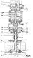
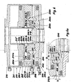
- the proposed device 100, 200 ( Figure 1 ) is used to drive a double seat valve, which consists essentially of a valve housing 1 with a first and a second valve housing part 1a and 1b, two independently movable, designed as a seat plate closing members 3 and 4, respectively associated Adjustment rods 3a and 4a, a seat ring 2, which establishes a connection between the valve housing parts 1a, 1b via its inside connection opening 2c, a lamp housing 6 connecting the second valve housing 1b to the device 100, 200, and a control device 7, the latter being mounted on the the double seat valve side facing away from the device 100, 200 is arranged.
- a double seat valve which consists essentially of a valve housing 1 with a first and a second valve housing part 1a and 1b, two independently movable, designed as a seat plate closing members 3 and 4, respectively associated Adjustment rods 3a and 4a, a seat ring 2, which establishes a connection between the valve housing parts 1a, 1b via its inside connection opening 2c, a
- the independently driven first closing member 3 is provided with a first seat seal 8 which acts both radially and axially and is associated with a first seating surface 2a ( FIG. 2 ) which is adjacent to an end portion of the area limiting the connection opening 2c in the first valve housing part 1a Seat ring 2 is formed.
- the dependent driven second closing member 4 has in its seat also a both radially from axially acting second seat seal 9, which cooperates with a formed on the other end of the seat ring 2 second seat 2b.
- a leakage cavity 5 is formed, which in the full open position H of the Dappelsitzventils ( Figure 3) by means of an exclusively axially acting seal 10, which is arranged in the leakage cavity 5 facing end face of the second closing member 4, with respect to his Environment is sealed.
- the double-seat valve is now equipped with the device 100, 200 according to the invention, for the opening and closing of the double seat valve in the context of the full opening stroke H the Kleinverstell responded 100 ( Figure 1 ) and for the production of partial open positions T1, T2 the Einzelverstell listeningen 200 has.
- the Kleinverstell issued 100 corresponds in its construction to a so-called. Standard drive with which only a double seat valve of the type in question can be fully opened and closed; Special functions, such as seat cleaning, can not be fulfilled with this standard drive.
- the main adjusting device 100 is designed in such a way that it can be connected directly to a latemet housing 6 which is adapted in length but otherwise unchanged when the individual adjusting devices 200 are omitted.
- the first adjusting rod 3a is in this end (bolt thread) configured such that it is both complementary to an end portion (nut thread) of a second drive rod 203 of the Einzelverstell Roaden 200 and complementary to an end portion (female thread) of a first drive rod 103 of the main adjustment device 100, with which it is screwed in case of need each.
- the second adjusting rod 4a continues above the cleaning agent connection 11 in a third drive rod 204 designed as a hollow rod and ends in the individual adjustment devices 200.
- a position message bar 7a is provided, which is bolted to the first drive rod 103 and ends in the control device 7.
- a first pressure medium connection 7b is provided on the control device 7, via which a first pressure medium flow D1 is supplied or removed. The latter passes on the way via a arranged in the first drive rod 103 pressure medium bore 103a in the Hauptverstell vibration 100.
- T2 To produce the partial open positions T1, T2 have the Einzelverstell noticeden 200 via a second and a third pressure medium connection 208, 209 for the second and third pressure medium flow D2, D3 , A fourth pressure medium connection 210 is closed by means of a sealing plug (not shown) and remains without function in the proposed device.
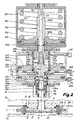
- the housing of the main adjusting device 100 ( Figure 2 , the plurality of seals of the device are not specifically described here and in the other figures) consists of a first and a second housing part 101, 102, which are made essentially of the same shape Ge Reifenoh puzzle.
- the first drive cam 104 On the first drive rod 103 provided with a piston seal the first drive cam 104 is arranged and fixed there with a mother unspecified.
- a prestressed main spring 105 finds on the one hand its abutment on the first drive piston 104 and on the other hand on the first housing part 101.
- the first drive rod 103 and the main spring 105 in the two housing parts 101, 102 are the latter preferably cohesively, preferably by Welding, interconnected.
- the seals and bushings in the housing 101/102 of the main adjustment device 100 are interchangeable even after final assembly.
- the concentric to the longitudinal axis of the first drive rod 103 arranged in this pressure medium bore 103a serves to transport the first pressure medium flow D1, which passes via transverse bores 103b into a first pressure medium chamber 100a formed between the first drive piston 104 and the second housing part 102, from where it also flows in the opposite direction.
- the Einzelverstell drivingen 200 are added additively. The latter sit down, seen from top to bottom, from a first Einzelverstell driving 200.1 for generating the first partial open position T1 of the first closing member 3 and a second Einzelverstell driving 200.2 for generating the second partial open position T2 of the second closing member 4 together.
- the housing of the Einzelverstell drivingen 200 is formed of a third and a fourth housing part 201, 202, which are essentially made of the same shape Ge Reifenoh sculpture and after assembly of the mounting parts preferably cohesively, preferably by welding, are interconnected.
- a circumferentially provided with a piston seal second drive piston 205 is disposed, and below the second drive piston 205 is provided in the fourth housing part 202 of the second Einzelverstell observed 200.2 a circumferentially provided with a piston seal third drive piston 206.
- the latter is axially displaceably mounted on the inner side on the formed as a hollow rod third drive rod 204 and with this in the direction of the second partially open position T2 at a formed on the end of the drive rod 204 first recess 204a in a driving connection.
- the second drive piston 205 is penetrated on the inside by a driver sleeve 212, which has a second recess 212a on its inside facing the third drive piston 206, and a third recess 212b on the outside, an axial distance from the latter.
- the driving sleeve 212 With the second recess 212a, the driving sleeve 212 is, if necessary, brought into a driving connection with the second drive rod 203, which widens in this area into a larger diameter head part 203a.
- the third recess 212b corresponds to a second driving surface 205a on the second drive piston 205, so that the latter engages in a direction of the first partial open position T1 sliding movement, the drive sleeve 212 in this direction.
- the drive sleeve 212 is internally mounted and sealed at its end facing away from the second drive piston 205 on a guide member 215, which engages from the outside in the third housing part 201, this complements complementary and the inside of the first drive rod 103 is penetrated concentrically.
- the guide part 215 is provided on the outside with a threaded part 215 a, onto which a stop nut 214 is screwed.
- the latter has at its periphery at least one recess 214b, by means of which a rotation and thus axial displacement is easy to carry out.
- the stop nut 214 is fixed immovably in a certain position on the guide member 215 (for example, by grub screw).
- One of the driver sleeve 212 facing end side of the stop nut 214 is formed as a fourth stop surface 214a, which corresponds to an associated end face of the driver sleeve 212, formed as a third stop surface 212c.
- the fourth stop surface 214a forms the stop which can be adjusted from outside the individual adjusting device 200 for limiting the first partial open position T1 of the first closing element 3.
- the access to the stopper nut 214 is effected in that the clamping ring connection between the main adjusting device 100 and the Einzelverstell Rheinen 200 solved and the main adjusting 100 is a piece axially away from the Einzelverstell Rheinen 200.
- the head part 203a comes to the guide part 215 to the system, so that in the further sliding movement, the stop nut 214, the third housing part 201 leaves to the outside and thus for the purpose of their axial adjustment is accessible from the outside.
- the second drive rod 203 is the main actuator 100 facing and subsequent to the extended head portion 203a end screwed in the region of the first Einzelverstell issued 200.1 via a bolt thread with the first drive rod 103, said screw being countered by a arranged on the bolt thread lock nut 211.
- the lock nut 211 comes on the one hand on a second stop surface 203b of the head part 203a and on the other hand on a first stop surface 103c formed as the end face of the first drive rod 103 to the plant.
- a second pressure medium chamber 200a which is connected to the second pressure medium connection 208, is circumferentially bounded by the housing 201/202 of the Einzelverstell Surpriseen 200, on the one end side by the second drive piston 205 and on the other end side by the third drive piston 206. Between the third drive piston 206 and the fourth housing part 202, a third Druckmittetraum 200 b is formed, which is connected to the third pressure medium connection 209.
- a second spring 207 is arranged in the region of the second Einzelverstell adopted 200.2 within an extension of the hollow rod-shaped third drive rod 204 whose bias is such that the second closing member 4 in its closed position with sufficient force on the assigned second seat 2b is pressed.
- the end position limitation of the third drive piston 206 for the second partially open position T2 is effected by a stop ring 213 fixedly arranged on both sides of the housing 201/202 between the drive pistons 205, 206 (see also FIG.
- the second drive piston 205 is thereby necessarily displaced correspondingly also via the third recess 212b of the driver sleeve 212, wherein in this end position it is still an axial safety distance, a fourth partial stroke d, away from the stop ring 213.
- the second drive link 205 will not come into contact with the stop ring 213 since there is no pressurization from the space between the second drive piston 205 and the third housing part 201. However, if there is a shift in this regard, then it is ensured in each case that the second drive shells 205 mounted on the drive sleeve 212 and remains sealed.
- the double-seat valve is transferred to its full open position H (FIG. 3) when the first pressure medium flow D1 of the main adjusting device 100 via the pressure medium bore 103 a, passes through the transverse bores 103 b in the first pressure medium chamber 100 a and there acts on the first drive piston 104.
- the thus pressurized drive piston 104 engages with its opening force, resulting from the pressure in the first pressure fluid chamber 100a and the intended effective piston surface, directly to the first drive rod 103 and thus overcomes the biasing force of the main spring 105 and possibly against the opening movement of the two Closing members 3, 4 attacking pressure and / or friction forces.
- the full open position H finds its end position limit either by conditioning the lock nut 211 on a fifth stop surface 215b on the inside of the guide member 215 or by conditioning the head portion 203a on a sixth stop surface 215c on the outside of the guide member 215th
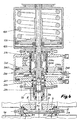
- the seat cleaning of the first closing member 3 is carried out by introducing the second pressure medium flow D2 in the second pressure medium chamber 200a of the first Einzelverstell Anlagenen 200.1 on the way via the second pressure medium connection 208.
- the pressurized medium second drive piston 205 is moved in the opening direction of the double seat valve and thereby transported via its second driving surface 205a, the driving sleeve 212 via the third recess 212b also in the same direction.
- the drive sleeve 212 comes to rest on its third stop surface 212c on the fourth stop surface 214a of the stop nut 214.
- the assigned first seat surface 2a is exposed gap-wide and the first seat cleaning flow R1 passes out of the first valve housing part 1a on the way across the gap-wide opened first seat 2a in the Leckagehohfraum. 5
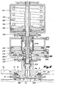
- the seat cleaning of the second closing member 4 ( FIG. 5 ) is accomplished by feeding the third pressure medium flow D3 via the third pressure medium connection 209 to the third pressure medium chamber 200b of the second individual adjusting device 200.2.
- the pressure medium-loaded third drive piston 206 moves in the direction of the stop ring 213 and has to overcome the second Operahubweg b to its local system (see Figure 2 ).
- the second closing member 4 is removed gap-wide from its associated second seat 2b, so that the second seat cleaning flow R2 from the second valve housing part 1 b passes through the gap between the exposed second seat 2b and the second seat seal 9 in the leakage cavity 5 ,
- the additional piston 206.1 has a larger diameter outer piston portion 206.1a and a smaller diameter inner piston portion 206.1b
- the outer piston portion 206.1a has an outer diameter D a
- the inner piston portion 206.1 b has an inner diameter D i ( Figure 6a).
- the inner piston portion 206.1b is frontally sealed by means of coaxially arranged seals 218 against the third drive piston 206 and screwed with this over a number distributed over the circumference arranged screw 206.2.
- the outer piston portion 206.1a is circumferentially sealed against the lateral surface of a cylindrical recess 213.1a in the housing ring 213.1 by means of a first piston seal 216.
- the inner piston section 206.1b is circumferentially sealed in a coaxial through-hole 213.1b in the housing ring 213.1 by means of a second piston seal 217.
- the third pressure medium flow D3 is first supplied via the third pressure medium connection 209 to the third pressure medium space 200b. From there, the pressure medium passes through an extending between the two seals 218 in the axial direction by the third drive piston 206 first pressure fluid passage 206b to then enter into a corresponding thereto, extending in the auxiliary piston 206.1 to the fourth pressure fluid chamber 200c second pressure fluid channel 206.1d.
- the housing ring 213.1 has on the circumference a radial projection 213.1c with which it is positively fixed in the connection area between the third and the fourth housing part 201, 202. Between the housing ring 213.1 and the third drive piston 206, an upstream second pressure medium chamber 200a * is formed, into which the second pressure medium connection 208 opens. About the latter, the second pressure medium flow D2 to complete the Operahubterrorism T1 for the independently driven closing member 3 is added or removed.
- the upstream second pressure medium chamber 200a * is connected to the second pressure medium chamber 200a formed between the second drive piston 205 on the one hand and the housing ring 213.1 in conjunction with the auxiliary piston 206.1 on the other hand via at least one connecting channel 213.1d, in a cylindrical Recess 213.1a outside part of the housing ring 213.1 is arranged.
- the radial projection 213.1c is formed on its side facing the third drive piston 206 in such a way that the latter undergoes an end position limitation there after completion of the second partial stroke b ( FIG. 6a ).
- a corresponding limitation of the first Operahubweges a takes place in the first Einzelverstell sensible 200.1 ( Figure 6 ), characterized in that a modified driving sleeve 212 * on the stopper nut 214, not shown (see Figure 2 ) comes to rest.
- the entrainment of the modified driver sleeve 212 * by the second driving surface 205a on the second drive piston 205 in cooperation with the third Rezess 212b realized the modified driving sleeve 212 *.
- the modified driving sleeve 212 * again engages on the head part 203a (not shown also in FIG. 4 ), in order thereby to move the first closing element 3, the independently driven closing element, into one or the other in the course of the first partial open position T1 To move direction.
- the third drive piston 206 engages via its third driving surface 206a on a not shown first Rezess 204a (see also Figure 5 ) of the third drive rod 204, also not shown, thereby completing the second partially open position T2 of the second closing member 4 in one or the other To effect direction.
- the axial extension of the third drive piston 206 facing the end of the modified driver sleeve 212 * makes it necessary to provide the additional piston 206.1 with a coaxial piston bore 206.1c, which surrounds the modified drive sleeve 212 * outside with play.
Landscapes
- Engineering & Computer Science (AREA)
- General Engineering & Computer Science (AREA)
- Mechanical Engineering (AREA)
- Fluid-Driven Valves (AREA)
- Lift Valve (AREA)
- Multiple-Way Valves (AREA)
Applications Claiming Priority (3)
| Application Number | Priority Date | Filing Date | Title |
|---|---|---|---|
| DE10237236A DE10237236B3 (de) | 2002-08-14 | 2002-08-14 | Vorrichtung zum Antrieb für Doppelsitzventile |
| DE10237236 | 2002-08-14 | ||
| PCT/EP2003/005508 WO2004023009A1 (de) | 2002-08-14 | 2003-05-26 | Vorrichtung zum antrieb für doppelsitzventile |
Publications (2)
| Publication Number | Publication Date |
|---|---|
| EP1529176A1 EP1529176A1 (de) | 2005-05-11 |
| EP1529176B1 true EP1529176B1 (de) | 2006-01-25 |
Family
ID=30775268
Family Applications (1)
| Application Number | Title | Priority Date | Filing Date |
|---|---|---|---|
| EP03793611A Expired - Lifetime EP1529176B1 (de) | 2002-08-14 | 2003-05-26 | Vorrichtung zum antrieb für doppelsitzventile |
Country Status (7)
| Country | Link |
|---|---|
| US (1) | US7198058B2 (da) |
| EP (1) | EP1529176B1 (da) |
| JP (1) | JP2005535857A (da) |
| AT (1) | ATE316627T1 (da) |
| DE (2) | DE10237236B3 (da) |
| DK (1) | DK1529176T3 (da) |
| WO (1) | WO2004023009A1 (da) |
Cited By (2)
| Publication number | Priority date | Publication date | Assignee | Title |
|---|---|---|---|---|
| WO2012031743A1 (de) | 2010-09-09 | 2012-03-15 | Gea Tuchenhagen Gmbh | Diagnose-verfahren für hubventile und messeinrichtung zu seiner durchführung |
| WO2013034295A1 (de) | 2011-09-10 | 2013-03-14 | Gea Tuchenhagen Gmbh | Ventil mit steuereinheit |
Families Citing this family (8)
| Publication number | Priority date | Publication date | Assignee | Title |
|---|---|---|---|---|
| US9273796B2 (en) | 2007-09-27 | 2016-03-01 | Kmatic Aps | Valve actuator system |
| WO2009039856A1 (en) * | 2007-09-27 | 2009-04-02 | Poul Elholm Jakobsen | Valve actuator system |
| DE102008004597B4 (de) * | 2008-01-16 | 2017-06-08 | Gea Tuchenhagen Gmbh | Sitzreinigungsfähiges Doppelsitzventil |
| ES2392317T3 (es) * | 2008-02-16 | 2012-12-07 | Gea Tuchenhagen Gmbh | Válvula elevadora, especialmente para la técnica de procesos |
| US8327881B2 (en) * | 2008-09-19 | 2012-12-11 | Spx Corporation | Double seat valve apparatus |
| DE102010030299A1 (de) | 2010-06-21 | 2011-12-22 | Krones Aktiengesellschaft | Vorrichtung zum Antreiben eines Doppelsitzventils |
| JP6384246B2 (ja) * | 2014-10-02 | 2018-09-05 | 株式会社Ihi | 空圧作動バルブ |
| DE202017103194U1 (de) | 2017-05-26 | 2018-08-28 | Neoperl Gmbh | Sanitärventil |
Family Cites Families (11)
| Publication number | Priority date | Publication date | Assignee | Title |
|---|---|---|---|---|
| DE3108973A1 (de) * | 1981-03-10 | 1982-10-07 | Holstein Und Kappert Gmbh, 4600 Dortmund | Steuerkopf fuer doppelsitzventile mit zwei unabhaengig voneinander bewegbaren ventiltellern |
| DE3133273C2 (de) * | 1981-08-22 | 1985-10-17 | Otto Tuchenhagen GmbH & Co KG, 2059 Büchen | Reinigbares Doppelsitzventil mit Leckkontrolle |
| US4605035A (en) * | 1984-09-14 | 1986-08-12 | Lavrids Knudsen Maskinefabrik A/S | Double seat valve |
| EP0646741B1 (de) * | 1993-09-21 | 1996-09-04 | Apv Rosista Gmbh | Leckagefrei schaltende Doppelventilanordnung |
| CA2238630A1 (en) * | 1995-12-20 | 1997-06-26 | Tuchenhagen Gmbh | Device for the drive system for double seat valves |
| DE19548860C1 (de) * | 1995-12-27 | 1997-01-16 | Tetra Laval Holdings & Finance | Absperrventil |
| DE19749279C2 (de) * | 1997-11-07 | 2000-05-18 | Schuck Franz Gmbh | Absperrvorrichtung für eine Rohrleitung |
| DE19900239C1 (de) | 1999-01-07 | 2000-06-21 | Tuchenhagen Gmbh | Antrieb für ein sitzreinigungsfähiges Doppelsitzventil |
| DE19906350A1 (de) * | 1999-02-17 | 1999-09-02 | Erhard Gmbh & Co | Anschlagmutter |
| DE50104688D1 (de) * | 2000-03-21 | 2005-01-05 | Tuchenhagen Gmbh | Sitzreinigungsfähiges aseptisches doppeldichtventil mit leckkontrolle |
| WO2001081228A1 (en) | 2000-04-20 | 2001-11-01 | Otis Elevator Company | Fluid-elastic vibration damper system |
-
2002
- 2002-08-14 DE DE10237236A patent/DE10237236B3/de not_active Expired - Fee Related
-
2003
- 2003-05-26 DE DE50302308T patent/DE50302308D1/de not_active Expired - Lifetime
- 2003-05-26 WO PCT/EP2003/005508 patent/WO2004023009A1/de not_active Ceased
- 2003-05-26 EP EP03793611A patent/EP1529176B1/de not_active Expired - Lifetime
- 2003-05-26 DK DK03793611T patent/DK1529176T3/da active
- 2003-05-26 AT AT03793611T patent/ATE316627T1/de not_active IP Right Cessation
- 2003-05-26 US US10/524,744 patent/US7198058B2/en not_active Expired - Fee Related
- 2003-05-26 JP JP2004533238A patent/JP2005535857A/ja active Pending
Cited By (4)
| Publication number | Priority date | Publication date | Assignee | Title |
|---|---|---|---|---|
| WO2012031743A1 (de) | 2010-09-09 | 2012-03-15 | Gea Tuchenhagen Gmbh | Diagnose-verfahren für hubventile und messeinrichtung zu seiner durchführung |
| WO2013034295A1 (de) | 2011-09-10 | 2013-03-14 | Gea Tuchenhagen Gmbh | Ventil mit steuereinheit |
| DE102011113046A1 (de) * | 2011-09-10 | 2013-03-14 | Gea Tuchenhagen Gmbh | Steuereinheit für ein Ventil |
| DE102011113046B4 (de) * | 2011-09-10 | 2013-04-11 | Gea Tuchenhagen Gmbh | Steuereinheit für ein Ventil |
Also Published As
| Publication number | Publication date |
|---|---|
| ATE316627T1 (de) | 2006-02-15 |
| WO2004023009A1 (de) | 2004-03-18 |
| US20050247343A1 (en) | 2005-11-10 |
| EP1529176A1 (de) | 2005-05-11 |
| DE50302308D1 (de) | 2006-04-13 |
| DE10237236B3 (de) | 2004-02-26 |
| US7198058B2 (en) | 2007-04-03 |
| DK1529176T3 (da) | 2006-05-22 |
| JP2005535857A (ja) | 2005-11-24 |
Similar Documents
| Publication | Publication Date | Title |
|---|---|---|
| EP1525415B1 (de) | Vorrichtung zum antrieb f r doppelsitzventile | |
| CH671080A5 (da) | ||
| EP1529176B1 (de) | Vorrichtung zum antrieb für doppelsitzventile | |
| DE10203886B4 (de) | Vorsteuerventil | |
| EP2252819A1 (de) | Vorrichtung zur verbindung eines ventilgehäuses mit einem stellantrieb bei einem als hubventil fungierenden prozessventil | |
| DE69417664T2 (de) | Sprühelement | |
| DE60302382T2 (de) | Hochdruckventil | |
| EP2235407B1 (de) | Sitzreinigungsfähiges doppelsitzventil | |
| EP1266159A1 (de) | Sitzreinigungsfähiges aseptisches doppeldichtventil mit leckkontrolle | |
| DE2544347A1 (de) | Ventilanordnung mit zwei stufen | |
| DE3506596A1 (de) | Steuerventil zum steuern der druckbeaufschlagung eines hydraulikstellgliedes | |
| EP2267343A1 (de) | Einschraub-Wege-Sitzventil | |
| DE102017105074B4 (de) | Steuerventil für Mittenverriegelung sowie Nockenwellenversteller | |
| DE2052748A1 (da) | ||
| DE19641073C2 (de) | Druckmittelbetätigbares Ventil | |
| DE9211629U1 (de) | Vorsteuerventil, insbesondere zur Verwendung in der Bergbauhydraulik | |
| DE69715199T2 (de) | Ventilanordnung für Heizsysteme und Wasserheizgeräte und Verfahren zu ihrer Herstellung | |
| DE3620242C2 (da) | ||
| EP1637727B1 (de) | Steuerventil für einen Injektor | |
| EP1320677B1 (de) | Ventilanordnung | |
| DE102019105710A1 (de) | Axialventil | |
| EP4093997B1 (de) | Ventil und verfahren zum reinigen | |
| EP3537017A1 (de) | Ventil | |
| DE3131943A1 (de) | Absperrschieber mit bei der betaetigung axial fester gewindespindel | |
| DE102006029523B4 (de) | Stellvorrichtung |
Legal Events
| Date | Code | Title | Description |
|---|---|---|---|
| PUAI | Public reference made under article 153(3) epc to a published international application that has entered the european phase |
Free format text: ORIGINAL CODE: 0009012 |
|
| 17P | Request for examination filed |
Effective date: 20041222 |
|
| AK | Designated contracting states |
Kind code of ref document: A1 Designated state(s): AT BE BG CH CY CZ DE DK EE ES FI FR GB GR HU IE IT LI LU MC NL PT RO SE SI SK TR |
|
| GRAP | Despatch of communication of intention to grant a patent |
Free format text: ORIGINAL CODE: EPIDOSNIGR1 |
|
| GRAS | Grant fee paid |
Free format text: ORIGINAL CODE: EPIDOSNIGR3 |
|
| GRAA | (expected) grant |
Free format text: ORIGINAL CODE: 0009210 |
|
| AK | Designated contracting states |
Kind code of ref document: B1 Designated state(s): AT BE BG CH CY CZ DE DK EE ES FI FR GB GR HU IE IT LI LU MC NL PT RO SE SI SK TR |
|
| PG25 | Lapsed in a contracting state [announced via postgrant information from national office to epo] |
Ref country code: SI Free format text: LAPSE BECAUSE OF FAILURE TO SUBMIT A TRANSLATION OF THE DESCRIPTION OR TO PAY THE FEE WITHIN THE PRESCRIBED TIME-LIMIT Effective date: 20060125 Ref country code: IT Free format text: LAPSE BECAUSE OF FAILURE TO SUBMIT A TRANSLATION OF THE DESCRIPTION OR TO PAY THE FEE WITHIN THE PRESCRIBED TIME-LIMIT;WARNING: LAPSES OF ITALIAN PATENTS WITH EFFECTIVE DATE BEFORE 2007 MAY HAVE OCCURRED AT ANY TIME BEFORE 2007. THE CORRECT EFFECTIVE DATE MAY BE DIFFERENT FROM THE ONE RECORDED. Effective date: 20060125 Ref country code: RO Free format text: LAPSE BECAUSE OF FAILURE TO SUBMIT A TRANSLATION OF THE DESCRIPTION OR TO PAY THE FEE WITHIN THE PRESCRIBED TIME-LIMIT Effective date: 20060125 Ref country code: SK Free format text: LAPSE BECAUSE OF FAILURE TO SUBMIT A TRANSLATION OF THE DESCRIPTION OR TO PAY THE FEE WITHIN THE PRESCRIBED TIME-LIMIT Effective date: 20060125 Ref country code: FI Free format text: LAPSE BECAUSE OF FAILURE TO SUBMIT A TRANSLATION OF THE DESCRIPTION OR TO PAY THE FEE WITHIN THE PRESCRIBED TIME-LIMIT Effective date: 20060125 Ref country code: NL Free format text: LAPSE BECAUSE OF FAILURE TO SUBMIT A TRANSLATION OF THE DESCRIPTION OR TO PAY THE FEE WITHIN THE PRESCRIBED TIME-LIMIT Effective date: 20060125 Ref country code: GB Free format text: LAPSE BECAUSE OF FAILURE TO SUBMIT A TRANSLATION OF THE DESCRIPTION OR TO PAY THE FEE WITHIN THE PRESCRIBED TIME-LIMIT Effective date: 20060125 Ref country code: IE Free format text: LAPSE BECAUSE OF FAILURE TO SUBMIT A TRANSLATION OF THE DESCRIPTION OR TO PAY THE FEE WITHIN THE PRESCRIBED TIME-LIMIT Effective date: 20060125 |
|
| REG | Reference to a national code |
Ref country code: GB Ref legal event code: FG4D Free format text: NOT ENGLISH |
|
| REG | Reference to a national code |
Ref country code: CH Ref legal event code: EP |
|
| REG | Reference to a national code |
Ref country code: IE Ref legal event code: FG4D Free format text: LANGUAGE OF EP DOCUMENT: GERMAN |
|
| REF | Corresponds to: |
Ref document number: 50302308 Country of ref document: DE Date of ref document: 20060413 Kind code of ref document: P |
|
| PG25 | Lapsed in a contracting state [announced via postgrant information from national office to epo] |
Ref country code: BG Free format text: LAPSE BECAUSE OF FAILURE TO SUBMIT A TRANSLATION OF THE DESCRIPTION OR TO PAY THE FEE WITHIN THE PRESCRIBED TIME-LIMIT Effective date: 20060425 Ref country code: SE Free format text: LAPSE BECAUSE OF FAILURE TO SUBMIT A TRANSLATION OF THE DESCRIPTION OR TO PAY THE FEE WITHIN THE PRESCRIBED TIME-LIMIT Effective date: 20060425 |
|
| PG25 | Lapsed in a contracting state [announced via postgrant information from national office to epo] |
Ref country code: ES Free format text: LAPSE BECAUSE OF FAILURE TO SUBMIT A TRANSLATION OF THE DESCRIPTION OR TO PAY THE FEE WITHIN THE PRESCRIBED TIME-LIMIT Effective date: 20060506 |
|
| REG | Reference to a national code |
Ref country code: DK Ref legal event code: T3 |
|
| PG25 | Lapsed in a contracting state [announced via postgrant information from national office to epo] |
Ref country code: AT Free format text: LAPSE BECAUSE OF NON-PAYMENT OF DUE FEES Effective date: 20060526 |
|
| PG25 | Lapsed in a contracting state [announced via postgrant information from national office to epo] |
Ref country code: MC Free format text: LAPSE BECAUSE OF NON-PAYMENT OF DUE FEES Effective date: 20060531 Ref country code: BE Free format text: LAPSE BECAUSE OF NON-PAYMENT OF DUE FEES Effective date: 20060531 |
|
| PG25 | Lapsed in a contracting state [announced via postgrant information from national office to epo] |
Ref country code: PT Free format text: LAPSE BECAUSE OF FAILURE TO SUBMIT A TRANSLATION OF THE DESCRIPTION OR TO PAY THE FEE WITHIN THE PRESCRIBED TIME-LIMIT Effective date: 20060626 |
|
| NLV1 | Nl: lapsed or annulled due to failure to fulfill the requirements of art. 29p and 29m of the patents act | ||
| GBV | Gb: ep patent (uk) treated as always having been void in accordance with gb section 77(7)/1977 [no translation filed] |
Effective date: 20060125 |
|
| REG | Reference to a national code |
Ref country code: IE Ref legal event code: FD4D |
|
| PLBI | Opposition filed |
Free format text: ORIGINAL CODE: 0009260 |
|
| PLAX | Notice of opposition and request to file observation + time limit sent |
Free format text: ORIGINAL CODE: EPIDOSNOBS2 |
|
| 26 | Opposition filed |
Opponent name: KIESELMANN GMBH Effective date: 20061025 |
|
| PLBB | Reply of patent proprietor to notice(s) of opposition received |
Free format text: ORIGINAL CODE: EPIDOSNOBS3 |
|
| BERE | Be: lapsed |
Owner name: TUCHENHAGEN G.M.B.H. Effective date: 20060531 |
|
| REG | Reference to a national code |
Ref country code: CH Ref legal event code: PL |
|
| PG25 | Lapsed in a contracting state [announced via postgrant information from national office to epo] |
Ref country code: LI Free format text: LAPSE BECAUSE OF NON-PAYMENT OF DUE FEES Effective date: 20070531 Ref country code: CH Free format text: LAPSE BECAUSE OF NON-PAYMENT OF DUE FEES Effective date: 20070531 |
|
| PG25 | Lapsed in a contracting state [announced via postgrant information from national office to epo] |
Ref country code: CZ Free format text: LAPSE BECAUSE OF FAILURE TO SUBMIT A TRANSLATION OF THE DESCRIPTION OR TO PAY THE FEE WITHIN THE PRESCRIBED TIME-LIMIT Effective date: 20060125 Ref country code: FR Free format text: LAPSE BECAUSE OF FAILURE TO SUBMIT A TRANSLATION OF THE DESCRIPTION OR TO PAY THE FEE WITHIN THE PRESCRIBED TIME-LIMIT Effective date: 20070316 Ref country code: GR Free format text: LAPSE BECAUSE OF FAILURE TO SUBMIT A TRANSLATION OF THE DESCRIPTION OR TO PAY THE FEE WITHIN THE PRESCRIBED TIME-LIMIT Effective date: 20060426 |
|
| PG25 | Lapsed in a contracting state [announced via postgrant information from national office to epo] |
Ref country code: EE Free format text: LAPSE BECAUSE OF FAILURE TO SUBMIT A TRANSLATION OF THE DESCRIPTION OR TO PAY THE FEE WITHIN THE PRESCRIBED TIME-LIMIT Effective date: 20060125 |
|
| PG25 | Lapsed in a contracting state [announced via postgrant information from national office to epo] |
Ref country code: LU Free format text: LAPSE BECAUSE OF NON-PAYMENT OF DUE FEES Effective date: 20060526 Ref country code: TR Free format text: LAPSE BECAUSE OF FAILURE TO SUBMIT A TRANSLATION OF THE DESCRIPTION OR TO PAY THE FEE WITHIN THE PRESCRIBED TIME-LIMIT Effective date: 20060125 Ref country code: HU Free format text: LAPSE BECAUSE OF FAILURE TO SUBMIT A TRANSLATION OF THE DESCRIPTION OR TO PAY THE FEE WITHIN THE PRESCRIBED TIME-LIMIT Effective date: 20060726 |
|
| PG25 | Lapsed in a contracting state [announced via postgrant information from national office to epo] |
Ref country code: FR Free format text: LAPSE BECAUSE OF FAILURE TO SUBMIT A TRANSLATION OF THE DESCRIPTION OR TO PAY THE FEE WITHIN THE PRESCRIBED TIME-LIMIT Effective date: 20060531 |
|
| PLCK | Communication despatched that opposition was rejected |
Free format text: ORIGINAL CODE: EPIDOSNREJ1 |
|
| PG25 | Lapsed in a contracting state [announced via postgrant information from national office to epo] |
Ref country code: CY Free format text: LAPSE BECAUSE OF FAILURE TO SUBMIT A TRANSLATION OF THE DESCRIPTION OR TO PAY THE FEE WITHIN THE PRESCRIBED TIME-LIMIT Effective date: 20060125 Ref country code: FR Free format text: LAPSE BECAUSE OF FAILURE TO SUBMIT A TRANSLATION OF THE DESCRIPTION OR TO PAY THE FEE WITHIN THE PRESCRIBED TIME-LIMIT Effective date: 20060125 |
|
| PLBN | Opposition rejected |
Free format text: ORIGINAL CODE: 0009273 |
|
| STAA | Information on the status of an ep patent application or granted ep patent |
Free format text: STATUS: OPPOSITION REJECTED |
|
| 27O | Opposition rejected |
Effective date: 20080925 |
|
| PGFP | Annual fee paid to national office [announced via postgrant information from national office to epo] |
Ref country code: DK Payment date: 20100525 Year of fee payment: 8 |
|
| PGFP | Annual fee paid to national office [announced via postgrant information from national office to epo] |
Ref country code: DE Payment date: 20100517 Year of fee payment: 8 |
|
| REG | Reference to a national code |
Ref country code: DK Ref legal event code: EBP |
|
| REG | Reference to a national code |
Ref country code: DE Ref legal event code: R119 Ref document number: 50302308 Country of ref document: DE Effective date: 20111201 |
|
| PG25 | Lapsed in a contracting state [announced via postgrant information from national office to epo] |
Ref country code: DK Free format text: LAPSE BECAUSE OF NON-PAYMENT OF DUE FEES Effective date: 20110531 |
|
| PG25 | Lapsed in a contracting state [announced via postgrant information from national office to epo] |
Ref country code: DE Free format text: LAPSE BECAUSE OF NON-PAYMENT OF DUE FEES Effective date: 20111201 |