EP1529181B1 - Chambre de combustion de turbine a gaz - Google Patents
Chambre de combustion de turbine a gaz Download PDFInfo
- Publication number
- EP1529181B1 EP1529181B1 EP03753347A EP03753347A EP1529181B1 EP 1529181 B1 EP1529181 B1 EP 1529181B1 EP 03753347 A EP03753347 A EP 03753347A EP 03753347 A EP03753347 A EP 03753347A EP 1529181 B1 EP1529181 B1 EP 1529181B1
- Authority
- EP
- European Patent Office
- Prior art keywords
- combustion chamber
- manhole
- manhole cover
- gas turbine
- cover
- Prior art date
- Legal status (The legal status is an assumption and is not a legal conclusion. Google has not performed a legal analysis and makes no representation as to the accuracy of the status listed.)
- Expired - Lifetime
Links
- 238000002485 combustion reaction Methods 0.000 title claims abstract description 86
- 238000001816 cooling Methods 0.000 claims abstract description 32
- 239000012530 fluid Substances 0.000 claims description 2
- 238000007789 sealing Methods 0.000 claims 1
- 239000007789 gas Substances 0.000 description 22
- 239000000446 fuel Substances 0.000 description 4
- 238000005253 cladding Methods 0.000 description 2
- 230000015572 biosynthetic process Effects 0.000 description 1
- 238000000576 coating method Methods 0.000 description 1
- 239000000567 combustion gas Substances 0.000 description 1
- 238000007689 inspection Methods 0.000 description 1
- 238000009434 installation Methods 0.000 description 1
- 239000007788 liquid Substances 0.000 description 1
- 230000000717 retained effect Effects 0.000 description 1
Images
Classifications
-
- F—MECHANICAL ENGINEERING; LIGHTING; HEATING; WEAPONS; BLASTING
- F23—COMBUSTION APPARATUS; COMBUSTION PROCESSES
- F23M—CASINGS, LININGS, WALLS OR DOORS SPECIALLY ADAPTED FOR COMBUSTION CHAMBERS, e.g. FIREBRIDGES; DEVICES FOR DEFLECTING AIR, FLAMES OR COMBUSTION PRODUCTS IN COMBUSTION CHAMBERS; SAFETY ARRANGEMENTS SPECIALLY ADAPTED FOR COMBUSTION APPARATUS; DETAILS OF COMBUSTION CHAMBERS, NOT OTHERWISE PROVIDED FOR
- F23M7/00—Doors
- F23M7/04—Cooling doors or door frames
-
- F—MECHANICAL ENGINEERING; LIGHTING; HEATING; WEAPONS; BLASTING
- F23—COMBUSTION APPARATUS; COMBUSTION PROCESSES
- F23R—GENERATING COMBUSTION PRODUCTS OF HIGH PRESSURE OR HIGH VELOCITY, e.g. GAS-TURBINE COMBUSTION CHAMBERS
- F23R3/00—Continuous combustion chambers using liquid or gaseous fuel
- F23R3/005—Combined with pressure or heat exchangers
Definitions
- the invention relates to a gas turbine combustion chamber with a manhole closable by a manhole cover as access to a combustion chamber interior.
- Gas turbines are used in many areas to drive generators or work machines.
- the energy content of a fuel is used to generate a rotational movement of a turbine shaft.
- the fuel is burned in a combustion chamber, compressed air being supplied by an air compressor.
- the working medium produced in the combustion chamber by the combustion of the fuel, under high pressure and at high temperature, is guided via a turbine unit arranged downstream of the combustion chamber, where it relaxes to perform work.
- a combustion chamber exposed to these temperatures during operation of the gas turbine should, for example for inspection purposes, be accessible from the inside.
- a gas turbine with a combustion chamber is known which has at least a portion which can be tested via a manhole access.
- a gas turbine with an annular combustion chamber is known, wherein an access (manhole) is provided in the flame space through which a person can get into the flame chamber.
- an access manhole
- a manhole in the combustion chamber since this would not withstand the prevailing thermal loads or at least could not ensure the tightness of the combustion chamber.
- the invention has for its object to provide a gas turbine combustor, which is suitable for a gas turbine with a particularly high combustion temperature and allows easy entry of a person.
- a gas turbine combustor having the features of claim 1.
- the gas turbine combustor on a manhole as access to a combustion chamber interior, which is closable with a manhole cover, which has an internal cooling space.
- the interior refrigerator i. the cooling space within the manhole cover, allows targeted cooling of the combustion chamber interior final manhole cover.
- the manhole cover is therefore usable even under high thermal loads in the combustion chamber interior, without deforming to an inadmissible extent. A tight closure of the combustion chamber interior through the manhole cover is guaranteed in all operating conditions.
- the combustion chamber wall in this case has a so-called wall cooling space.
- the internal cooling space of the manhole cover is fluidically connectable, for example by means of connecting lines, with the wall cooling space of the combustion chamber wall.
- a fluidic connection between the internal cooling space of the manhole cover and the wall cooling space of the combustion chamber wall can be produced in a particularly simple manner directly by inserting the manhole cover into the manhole.
- the wall cooling space of the combustion chamber wall without cross-sectional reduction merges into the internal cooling space of the manhole cover.
- the entire wall of the gas turbine combustor including manhole cover forms a homogeneous cooling space.
- the manhole cover or at least one Deckeleinzelteil the manhole cover for example, a cover inner lining, which closes the inner cooling chamber of the manhole cover to the combustion chamber interior, supported by a fastener to the combustion chamber interior, said fastener also holds a manhole cover adjacent interior trim element on the combustion chamber.
- the fastener is preferably at least substantially U-shaped in cross-section, wherein a first U-leg supports the Deckeleinzelteil the manhole cover and a second U-leg holds the inner lining element to the combustion chamber.
- the entire fastening element preferably has the shape of a rail. Due to the design of the fastening element as a U-rail, this has both a sufficient stability and elasticity.
- the fastening element is preferably held on the combustion chamber wall in such a way that a section, in particular a U-leg, of the fastening element protrudes into the manhole and supports the inner cover of the manhole cover toward the combustion chamber interior, and the manhole cover can be removed from the manhole without loosening the fastening element ,
- This has the advantage that all fasteners that hold both the inner lining elements and the inner cover lining to the combustion chamber or manhole cover, need only be attached once and an entry into the gas turbine combustor through the manhole without removing one of these fasteners is possible.
- the advantage of the invention lies in particular in the fact that the manhole cover withstands high thermal loads due to an internal cooling space, whereby a very simple removal of the manhole cover including its internal cooling space from the manhole is made possible.
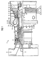
- the gas turbine 1 has a compressor 2 for combustion air, a combustion chamber or gas turbine combustor 4 and a turbine 6 for driving the compressor 2 and a generator, not shown, or a working machine.
- the turbine 6 and the compressor 2 are arranged on a common, also called turbine rotor turbine shaft 8, with the generator or the Working machine is connected, and which is rotatably mounted about its central axis 9.
- the combustion chamber 4 is equipped with a number of burners 10 for the combustion of a liquid or gaseous fuel. It is also provided on its inner wall or Brennschwandung 23 with interior trim elements 25.
- the turbine 6 has a number of rotatable blades 12 connected to the turbine shaft 8.
- the blades 12 are arranged in a ring on the turbine shaft 8 and thus form a number of blade rows.
- the turbine 6 comprises a number of fixed vanes 14, which are also fixed in a ring shape with the formation of rows of vanes on an inner casing 16 of the turbine 6.
- the blades 12 serve to drive the turbine shaft 8 by momentum transfer from the turbine 6 flowing through the working medium M.
- the vanes 14, however, serve to guide the flow of the working medium M between two seen in the flow direction of the working medium M consecutive blade rows or blade rings.
- a successive pair of a ring of vanes 14 or a row of vanes and a ring of blades 12 or a blade row is also referred to as a turbine stage.
- Each vane 14 has a platform 18, also referred to as a blade root 19, which is arranged to fix the respective vane 14 on the inner housing 16 of the turbine 6 as a wall element.
- the platform 18 is a thermally comparatively heavily loaded component, which forms the outer boundary of a hot gas channel for the working medium M flowing through the turbine 6.
- Each blade 12 is attached to the turbine shaft 8 in an analogous manner via a blade root 19, also referred to as a platform 18, the blade root 19 each carrying a profiled blade 20 extended along a blade axis.
- each guide ring 21 on the inner housing 16 of the turbine 6 is arranged between the spaced-apart platforms 18 of the guide vanes 14 of two adjacent rows of guide vanes.
- the outer surface of each guide ring 21 is also exposed to the hot, the turbine 6 flowing through the working medium M and spaced in the radial direction from the outer end 22 of the blade 12 opposite him through a gap.
- the guide rings 21 arranged between adjacent rows of guide blades serve in particular as cover elements which protect the inner wall 16 or other housing installation parts from thermal overload by the hot working medium M flowing through the turbine 6.
- the gas turbine 1 is designed for a comparatively high outlet temperature of the working medium M emerging from the combustion chamber 4 from about 1200 ° C. to 1300 ° C.
- the combustion chamber wall 23 is internally cooled.
- combustion air flows in countercurrent to the working medium M, i. the combustion gases, between the combustion chamber wall 23 and attached thereto, the combustion chamber interior 24 surrounding inner lining elements 25 through a Wandungskühlraum 26 to the burners 10.
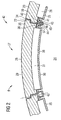
- FIG. 2 shows a fragmentary cross-section of the combustion chamber wall 23 with a manhole 27, in which a manhole cover 28 is inserted.
- the manhole cover 28 has an upper cover part 29, which is formed comparable to the Brennschdung 23, and a cover inner panel 30. Between the upper cover part 29 and the inner cover 30, which are also referred to as Deckeleinzelmaschine, an internal cooling chamber 31 of the manhole cover 27 is included. In a similar way is between the combustion chamber wall 23 and an inner lining element 25 fastened to the latter are enclosed in a wall cooling space 26.
- the internal cooling space 31 of the manhole cover 27 is connected to the wall cooling space 26 of the combustion chamber wall 23 such that the combustion air can flow unhindered, perpendicular to the plane shown.
- the upper cover part 29 has at its edge a projection 33, with which this can be inserted into a corresponding retaining recess 34 of the combustion chamber wall 23.
- the manhole cover 28 has an overall rectangular basic shape.
- the top cover 29 and the combustion chamber wall 23 are in the region of the connection between these two components, i. formed thickened in the region of the projection 33 and the retaining recess 34 to increase the stability to the combustion chamber interior 24.
- this has a contact surface 36 on which the inner cover edge 30 rests with an inner lining edge 37.
- the inner lining edge 37 is, following an inner lining main surface 38, formed integrally with this and bent from this.
- a trim edge 41 of the inner lining element 25 is on a contact surface 39 of a reinforced or thickened portion 40 of the combustion chamber wall 23 a trim edge 41 of the inner lining element 25 at.
- the manhole cover 28 is supported to the combustion chamber outside 42 through a fastening device, not shown. Both the inner cover cladding 30 and the inner cladding element 25 are supported towards the combustion chamber interior 24 by a fastening element 43 designed as a U-rail.
- a fastening element 43 designed as a U-rail.
- the U-legs 44,45 are also referred to as sections of the fastener 43.
- the fastening elements 43 are held by screws 46 which engage in the reinforced area 40 of the combustion chamber wall 23.
- the screws 46 are screwed from the combustion chamber interior 24 into the combustion chamber wall 23. An additional attachment of the inner lining element 31 on the reinforced area 40 is not required.
- the U-shaped fastener 43 held by the screws 46 on the combustion chamber wall 23 is sufficient to both hold the inner lining element 25 against the combustion chamber wall 23 and to support the inner cover 30 to the combustion chamber interior 24.
- the coatings 25, 30, which are also referred to as liners, are sealed by the fastening element 43.
- An escape of cooling air in the region of the fastening element 43 is excluded. As far as cooling air would escape from the wall cooling space 26 or the inner cooling chamber 31 on the inner lining edge 37 or on the trim edge 41, this leaked cooling air would be prevented by the U-shaped fastening element 43 from flowing into the combustion chamber interior 24. In contrast, this retained by the U-shaped fastening element 43 cooling air flow unhindered along the trained as a rail fastener 43 to the burners 10.
Landscapes
- Engineering & Computer Science (AREA)
- Chemical & Material Sciences (AREA)
- Combustion & Propulsion (AREA)
- Mechanical Engineering (AREA)
- General Engineering & Computer Science (AREA)
- Incineration Of Waste (AREA)
- Turbine Rotor Nozzle Sealing (AREA)
- Heat-Exchange Devices With Radiators And Conduit Assemblies (AREA)
- Air Supply (AREA)
Abstract
Claims (7)
- Chambre de combustion (4) de turbine à gaz, comprenant un trou d'homme (27), pouvant être fermé par un couvercle (28) de trou d'homme et servant d'accès à l'intérieur (24) de la chambre de combustion, et un couvercle de trou d'homme pour fermer le trou d'homme, caractérisée par un espace (31) de refroidissement disposé à l'intérieur du couvercle (28) de trou d'homme.
- Chambre de combustion (4) de turbine à gaz suivant la revendication 1, caractériseé par un espace (26) de refroidissement d'une paroi (23) de la chambre de combustion.
- Chambre de combustion (4) de turbine à gaz suivant la revendication 2, caractérisée en ce que l'espace (31) intérieur de refroidissement du couvercle (28) de trou d'homme peut communiquer du point de vue fluidique avec l'espace (26) de refroidissement de la paroi (23) de la chambre de combustion.
- Chambre de combustion (4) de turbine à gaz suivant la revendication 3, caractérisée en ce que l'espace (31) intérieur de refroidissement du couvercle (28) de trou d'homme peut communiquer directement avec l'espace (26) de refroidissement de la paroi (23) de la chambre de combustion en mettant le couvercle (28) de trou d'homme dans le trou d'homme (27).
- Chambre de combustion (4) de turbine à gaz suivant la revendication 2, caractérisée par un élément (43) de fixation, qui soutient au moins une partie (29, 30) individuelle du couvercle (28) du trou d'homme en direction de l'intérieur (24) de la chambre de combustion et en même temps maintient sur la paroi (23) de la chambre de combustion un élément (25) intérieur de garnissage voisin du couvercle (28) de trou d'homme.
- Chambre de combustion (4) de turbine à gaz suivant la revendication 5, caractérisée en ce que l'élément (43) de fixation a en section transversale une forme au moins sensiblement en U, une première branche (44) du U soutenant la partie (29, 30) individuelle du couvercle et une deuxième branche (45) du U maintenant l'élément (25) intérieur de garnissage.
- Chambre de combustion (4) de turbine à gaz suivant la revendication 5 ou 6, caractérisée en ce qu'une sous pièce (44, 45) de l'élément (43) de fixation pénètre dans le trou d'homme (27) de sorte qu'un garnissage (30) intérieur du couvercle (28) de trou d'homme est soutenu en direction de l'intérieur (24) de la chambre de combustion et que le couvercle (28) de trou d'homme peut être retiré du trou d'homme (27).
Priority Applications (1)
| Application Number | Priority Date | Filing Date | Title |
|---|---|---|---|
| EP03753347A EP1529181B1 (fr) | 2002-08-16 | 2003-08-01 | Chambre de combustion de turbine a gaz |
Applications Claiming Priority (4)
| Application Number | Priority Date | Filing Date | Title |
|---|---|---|---|
| EP02018489 | 2002-08-16 | ||
| EP02018489A EP1389714A1 (fr) | 2002-08-16 | 2002-08-16 | Chambre à combustion de turbine à gaz |
| PCT/EP2003/008548 WO2004023042A1 (fr) | 2002-08-16 | 2003-08-01 | Chambre de combustion de turbine a gaz |
| EP03753347A EP1529181B1 (fr) | 2002-08-16 | 2003-08-01 | Chambre de combustion de turbine a gaz |
Publications (2)
| Publication Number | Publication Date |
|---|---|
| EP1529181A1 EP1529181A1 (fr) | 2005-05-11 |
| EP1529181B1 true EP1529181B1 (fr) | 2008-04-09 |
Family
ID=30470278
Family Applications (2)
| Application Number | Title | Priority Date | Filing Date |
|---|---|---|---|
| EP02018489A Withdrawn EP1389714A1 (fr) | 2002-08-16 | 2002-08-16 | Chambre à combustion de turbine à gaz |
| EP03753347A Expired - Lifetime EP1529181B1 (fr) | 2002-08-16 | 2003-08-01 | Chambre de combustion de turbine a gaz |
Family Applications Before (1)
| Application Number | Title | Priority Date | Filing Date |
|---|---|---|---|
| EP02018489A Withdrawn EP1389714A1 (fr) | 2002-08-16 | 2002-08-16 | Chambre à combustion de turbine à gaz |
Country Status (6)
| Country | Link |
|---|---|
| US (1) | US20060037321A1 (fr) |
| EP (2) | EP1389714A1 (fr) |
| JP (1) | JP4167224B2 (fr) |
| CN (1) | CN1318805C (fr) |
| DE (1) | DE50309588D1 (fr) |
| WO (1) | WO2004023042A1 (fr) |
Families Citing this family (5)
| Publication number | Priority date | Publication date | Assignee | Title |
|---|---|---|---|---|
| EP1398569A1 (fr) * | 2002-09-13 | 2004-03-17 | Siemens Aktiengesellschaft | Turbine à gaz |
| EP1862740B1 (fr) * | 2006-05-31 | 2015-09-16 | Siemens Aktiengesellschaft | Paroi de chambre de combustion |
| EP2426321A1 (fr) | 2010-09-03 | 2012-03-07 | Siemens Aktiengesellschaft | Boîtier pour une turbine à gaz |
| US9534783B2 (en) * | 2011-07-21 | 2017-01-03 | United Technologies Corporation | Insert adjacent to a heat shield element for a gas turbine engine combustor |
| EP3134680B1 (fr) * | 2014-09-29 | 2018-07-04 | Siemens Aktiengesellschaft | Élément de bouclier thermique pour bouclier thermique d'une chambre de combustion |
Family Cites Families (10)
| Publication number | Priority date | Publication date | Assignee | Title |
|---|---|---|---|---|
| GB626249A (en) * | 1946-05-23 | 1949-07-12 | Babcock & Wilcox Ltd | Improvements in or relating to closure means for openings in walls of chambers arranged to contain gas under pressure |
| US4480436A (en) * | 1972-12-19 | 1984-11-06 | General Electric Company | Combustion chamber construction |
| US3978662A (en) * | 1975-04-28 | 1976-09-07 | General Electric Company | Cooling ring construction for combustion chambers |
| US4189352A (en) * | 1975-08-14 | 1980-02-19 | Krupp-Koppers, Gmbh | Coke oven door |
| US5333443A (en) * | 1993-02-08 | 1994-08-02 | General Electric Company | Seal assembly |
| DE19502730A1 (de) * | 1995-01-28 | 1996-08-01 | Abb Management Ag | Keramische Auskleidung |
| US5782294A (en) * | 1995-12-18 | 1998-07-21 | United Technologies Corporation | Cooled liner apparatus |
| DE19809568A1 (de) | 1998-03-05 | 1999-08-19 | Siemens Ag | Ringbrennkammer, Verwendung einer Ringbrennkammer und Einsatz für eine Öffnung in einer Brennkammer |
| US6415724B1 (en) * | 1999-01-01 | 2002-07-09 | The Babcock & Wilcox Company | Water-jacketed, high-temperature, stretcher-accessible door for a boiler |
| DE19924607A1 (de) | 1999-05-28 | 2000-11-30 | Siemens Ag | Inspektionsvorrichtung für eine Ringbrennkammer einer Gasturbine und Verfahren zur Inspektion einer Ringbrennkammer einer Gasturbine |
-
2002
- 2002-08-16 EP EP02018489A patent/EP1389714A1/fr not_active Withdrawn
-
2003
- 2003-08-01 WO PCT/EP2003/008548 patent/WO2004023042A1/fr not_active Ceased
- 2003-08-01 US US10/524,523 patent/US20060037321A1/en not_active Abandoned
- 2003-08-01 JP JP2004533306A patent/JP4167224B2/ja not_active Expired - Fee Related
- 2003-08-01 CN CNB038188929A patent/CN1318805C/zh not_active Expired - Fee Related
- 2003-08-01 DE DE50309588T patent/DE50309588D1/de not_active Expired - Lifetime
- 2003-08-01 EP EP03753347A patent/EP1529181B1/fr not_active Expired - Lifetime
Also Published As
| Publication number | Publication date |
|---|---|
| US20060037321A1 (en) | 2006-02-23 |
| CN1675502A (zh) | 2005-09-28 |
| CN1318805C (zh) | 2007-05-30 |
| WO2004023042A1 (fr) | 2004-03-18 |
| EP1389714A1 (fr) | 2004-02-18 |
| JP4167224B2 (ja) | 2008-10-15 |
| EP1529181A1 (fr) | 2005-05-11 |
| DE50309588D1 (de) | 2008-05-21 |
| JP2005535867A (ja) | 2005-11-24 |
Similar Documents
| Publication | Publication Date | Title |
|---|---|---|
| DE69936176T2 (de) | Berstschutzring für Turbinen | |
| EP2344723B1 (fr) | Turbine à gaz avec plaques d'étanchéité sur le disque de turbine | |
| DE19821889B4 (de) | Verfahren und Vorrichtung zur Durchführung von Reparatur- und/oder Wartungsarbeiten im Innengehäuse einer mehrschaligen Turbomaschine | |
| EP1183444B1 (fr) | Turbomachine ainsi qu'element d'etancheite pour un rotor d'une turbomachine | |
| EP1413831A1 (fr) | Chambre de combustion annulaire pour turbine à gaz et turbine à gaz | |
| DE112013006128T5 (de) | Laufschaufel und zugehöriges Herstellungsverfahren | |
| EP2342425B1 (fr) | Turbine à gaz avec plaque de fixation entre la base d'aube et le disque | |
| DE102014204481A1 (de) | Brennkammer einer Gasturbine | |
| EP2084368A1 (fr) | Aube de turbine | |
| DE102015205975A1 (de) | Umführungs-Hitzeschildelement | |
| WO2015022222A1 (fr) | Écran thermique comportant un résonateur de helmholtz | |
| EP1529181B1 (fr) | Chambre de combustion de turbine a gaz | |
| EP2236759A1 (fr) | Système d'aube | |
| EP1926927A1 (fr) | Garniture d'etancheite resistant aux temperatures elevees, conçue en particulier pour des turbines a gaz | |
| EP0616679B1 (fr) | Refroidisseur a air froid pour turbines a gaz | |
| EP2206885A1 (fr) | Turbine à gaz | |
| EP1904717B1 (fr) | Element de carter conducteur de gaz chaud, enveloppe de protection d'arbre et systeme de turbine a gaz | |
| EP1467151A1 (fr) | Bouclier thermique | |
| WO2009109430A1 (fr) | Dispositif d’étanchéité et turbine à gaz | |
| CH643050A5 (de) | Gasturbinentriebwerk mit ringbrennkammer. | |
| WO2006120204A1 (fr) | Paroi de chambre de combustion, systeme de turbine a gaz et procede pour demarrer ou arreter un systeme de turbine a gaz | |
| EP1247943A1 (fr) | Segment de virole réfroidi pour turbine à gaz | |
| EP1429077B1 (fr) | Turbine à gaz | |
| EP1537363A1 (fr) | Turbine a gaz | |
| EP1422479B1 (fr) | Chambre pour la combustion d' un mélange combustible fluide |
Legal Events
| Date | Code | Title | Description |
|---|---|---|---|
| PUAI | Public reference made under article 153(3) epc to a published international application that has entered the european phase |
Free format text: ORIGINAL CODE: 0009012 |
|
| 17P | Request for examination filed |
Effective date: 20050120 |
|
| AK | Designated contracting states |
Kind code of ref document: A1 Designated state(s): AT BE BG CH CY CZ DE DK EE ES FI FR GB GR HU IE IT LI LU MC NL PT RO SE SI SK TR |
|
| RBV | Designated contracting states (corrected) |
Designated state(s): CH DE FR GB IT LI |
|
| GRAP | Despatch of communication of intention to grant a patent |
Free format text: ORIGINAL CODE: EPIDOSNIGR1 |
|
| GRAS | Grant fee paid |
Free format text: ORIGINAL CODE: EPIDOSNIGR3 |
|
| GRAA | (expected) grant |
Free format text: ORIGINAL CODE: 0009210 |
|
| AK | Designated contracting states |
Kind code of ref document: B1 Designated state(s): CH DE FR GB IT LI |
|
| REG | Reference to a national code |
Ref country code: GB Ref legal event code: FG4D Free format text: NOT ENGLISH |
|
| REG | Reference to a national code |
Ref country code: CH Ref legal event code: NV Representative=s name: SIEMENS SCHWEIZ AG Ref country code: CH Ref legal event code: EP |
|
| GBT | Gb: translation of ep patent filed (gb section 77(6)(a)/1977) |
Effective date: 20080415 |
|
| REF | Corresponds to: |
Ref document number: 50309588 Country of ref document: DE Date of ref document: 20080521 Kind code of ref document: P |
|
| ET | Fr: translation filed | ||
| PLBE | No opposition filed within time limit |
Free format text: ORIGINAL CODE: 0009261 |
|
| STAA | Information on the status of an ep patent application or granted ep patent |
Free format text: STATUS: NO OPPOSITION FILED WITHIN TIME LIMIT |
|
| 26N | No opposition filed |
Effective date: 20090112 |
|
| REG | Reference to a national code |
Ref country code: CH Ref legal event code: PCAR Free format text: SIEMENS SCHWEIZ AG;INTELLECTUAL PROPERTY FREILAGERSTRASSE 40;8047 ZUERICH (CH) |
|
| REG | Reference to a national code |
Ref country code: FR Ref legal event code: PLFP Year of fee payment: 13 |
|
| PGFP | Annual fee paid to national office [announced via postgrant information from national office to epo] |
Ref country code: GB Payment date: 20150812 Year of fee payment: 13 |
|
| PGFP | Annual fee paid to national office [announced via postgrant information from national office to epo] |
Ref country code: FR Payment date: 20150818 Year of fee payment: 13 |
|
| PGFP | Annual fee paid to national office [announced via postgrant information from national office to epo] |
Ref country code: IT Payment date: 20150825 Year of fee payment: 13 |
|
| PGFP | Annual fee paid to national office [announced via postgrant information from national office to epo] |
Ref country code: CH Payment date: 20151102 Year of fee payment: 13 Ref country code: DE Payment date: 20151016 Year of fee payment: 13 |
|
| REG | Reference to a national code |
Ref country code: DE Ref legal event code: R119 Ref document number: 50309588 Country of ref document: DE |
|
| REG | Reference to a national code |
Ref country code: CH Ref legal event code: PL |
|
| GBPC | Gb: european patent ceased through non-payment of renewal fee |
Effective date: 20160801 |
|
| PG25 | Lapsed in a contracting state [announced via postgrant information from national office to epo] |
Ref country code: LI Free format text: LAPSE BECAUSE OF NON-PAYMENT OF DUE FEES Effective date: 20160831 Ref country code: CH Free format text: LAPSE BECAUSE OF NON-PAYMENT OF DUE FEES Effective date: 20160831 |
|
| REG | Reference to a national code |
Ref country code: FR Ref legal event code: ST Effective date: 20170428 |
|
| PG25 | Lapsed in a contracting state [announced via postgrant information from national office to epo] |
Ref country code: FR Free format text: LAPSE BECAUSE OF NON-PAYMENT OF DUE FEES Effective date: 20160831 Ref country code: GB Free format text: LAPSE BECAUSE OF NON-PAYMENT OF DUE FEES Effective date: 20160801 Ref country code: DE Free format text: LAPSE BECAUSE OF NON-PAYMENT OF DUE FEES Effective date: 20170301 |
|
| PG25 | Lapsed in a contracting state [announced via postgrant information from national office to epo] |
Ref country code: IT Free format text: LAPSE BECAUSE OF NON-PAYMENT OF DUE FEES Effective date: 20160801 |