EP1529567A2 - Porte échantillon avec chambre de réaction - Google Patents
Porte échantillon avec chambre de réaction Download PDFInfo
- Publication number
- EP1529567A2 EP1529567A2 EP04024263A EP04024263A EP1529567A2 EP 1529567 A2 EP1529567 A2 EP 1529567A2 EP 04024263 A EP04024263 A EP 04024263A EP 04024263 A EP04024263 A EP 04024263A EP 1529567 A2 EP1529567 A2 EP 1529567A2
- Authority
- EP
- European Patent Office
- Prior art keywords
- reaction chamber
- sample carrier
- channel
- walls
- reaction
- Prior art date
- Legal status (The legal status is an assumption and is not a legal conclusion. Google has not performed a legal analysis and makes no representation as to the accuracy of the status listed.)
- Withdrawn
Links
Images



Classifications
-
- B—PERFORMING OPERATIONS; TRANSPORTING
- B01—PHYSICAL OR CHEMICAL PROCESSES OR APPARATUS IN GENERAL
- B01L—CHEMICAL OR PHYSICAL LABORATORY APPARATUS FOR GENERAL USE
- B01L3/00—Containers or dishes for laboratory use, e.g. laboratory glassware; Droppers
- B01L3/50—Containers for the purpose of retaining a material to be analysed, e.g. test tubes
- B01L3/502—Containers for the purpose of retaining a material to be analysed, e.g. test tubes with fluid transport, e.g. in multi-compartment structures
- B01L3/5027—Containers for the purpose of retaining a material to be analysed, e.g. test tubes with fluid transport, e.g. in multi-compartment structures by integrated microfluidic structures, i.e. dimensions of channels and chambers are such that surface tension forces are important, e.g. lab-on-a-chip
- B01L3/502723—Containers for the purpose of retaining a material to be analysed, e.g. test tubes with fluid transport, e.g. in multi-compartment structures by integrated microfluidic structures, i.e. dimensions of channels and chambers are such that surface tension forces are important, e.g. lab-on-a-chip characterised by venting arrangements
-
- B—PERFORMING OPERATIONS; TRANSPORTING
- B01—PHYSICAL OR CHEMICAL PROCESSES OR APPARATUS IN GENERAL
- B01L—CHEMICAL OR PHYSICAL LABORATORY APPARATUS FOR GENERAL USE
- B01L3/00—Containers or dishes for laboratory use, e.g. laboratory glassware; Droppers
- B01L3/50—Containers for the purpose of retaining a material to be analysed, e.g. test tubes
- B01L3/502—Containers for the purpose of retaining a material to be analysed, e.g. test tubes with fluid transport, e.g. in multi-compartment structures
- B01L3/5027—Containers for the purpose of retaining a material to be analysed, e.g. test tubes with fluid transport, e.g. in multi-compartment structures by integrated microfluidic structures, i.e. dimensions of channels and chambers are such that surface tension forces are important, e.g. lab-on-a-chip
- B01L3/502707—Containers for the purpose of retaining a material to be analysed, e.g. test tubes with fluid transport, e.g. in multi-compartment structures by integrated microfluidic structures, i.e. dimensions of channels and chambers are such that surface tension forces are important, e.g. lab-on-a-chip characterised by the manufacture of the container or its components
-
- B—PERFORMING OPERATIONS; TRANSPORTING
- B01—PHYSICAL OR CHEMICAL PROCESSES OR APPARATUS IN GENERAL
- B01L—CHEMICAL OR PHYSICAL LABORATORY APPARATUS FOR GENERAL USE
- B01L3/00—Containers or dishes for laboratory use, e.g. laboratory glassware; Droppers
- B01L3/50—Containers for the purpose of retaining a material to be analysed, e.g. test tubes
- B01L3/508—Rigid containers without fluid transport within
- B01L3/5085—Rigid containers without fluid transport within for multiple samples, e.g. microtitration plates
-
- G—PHYSICS
- G01—MEASURING; TESTING
- G01N—INVESTIGATING OR ANALYSING MATERIALS BY DETERMINING THEIR CHEMICAL OR PHYSICAL PROPERTIES
- G01N21/00—Investigating or analysing materials by the use of optical means, i.e. using sub-millimetre waves, infrared, visible or ultraviolet light
- G01N21/01—Arrangements or apparatus for facilitating the optical investigation
- G01N21/03—Cuvette constructions
- G01N21/0303—Optical path conditioning in cuvettes, e.g. windows; adapted optical elements or systems; path modifying or adjustment
-
- B—PERFORMING OPERATIONS; TRANSPORTING
- B01—PHYSICAL OR CHEMICAL PROCESSES OR APPARATUS IN GENERAL
- B01L—CHEMICAL OR PHYSICAL LABORATORY APPARATUS FOR GENERAL USE
- B01L2200/00—Solutions for specific problems relating to chemical or physical laboratory apparatus
- B01L2200/06—Fluid handling related problems
- B01L2200/0684—Venting, avoiding backpressure, avoid gas bubbles
-
- B—PERFORMING OPERATIONS; TRANSPORTING
- B01—PHYSICAL OR CHEMICAL PROCESSES OR APPARATUS IN GENERAL
- B01L—CHEMICAL OR PHYSICAL LABORATORY APPARATUS FOR GENERAL USE
- B01L2200/00—Solutions for specific problems relating to chemical or physical laboratory apparatus
- B01L2200/14—Process control and prevention of errors
- B01L2200/142—Preventing evaporation
-
- B—PERFORMING OPERATIONS; TRANSPORTING
- B01—PHYSICAL OR CHEMICAL PROCESSES OR APPARATUS IN GENERAL
- B01L—CHEMICAL OR PHYSICAL LABORATORY APPARATUS FOR GENERAL USE
- B01L2300/00—Additional constructional details
- B01L2300/08—Geometry, shape and general structure
- B01L2300/0809—Geometry, shape and general structure rectangular shaped
- B01L2300/0816—Cards, e.g. flat sample carriers usually with flow in two horizontal directions
-
- B—PERFORMING OPERATIONS; TRANSPORTING
- B01—PHYSICAL OR CHEMICAL PROCESSES OR APPARATUS IN GENERAL
- B01L—CHEMICAL OR PHYSICAL LABORATORY APPARATUS FOR GENERAL USE
- B01L2300/00—Additional constructional details
- B01L2300/08—Geometry, shape and general structure
- B01L2300/0861—Configuration of multiple channels and/or chambers in a single devices
- B01L2300/0864—Configuration of multiple channels and/or chambers in a single devices comprising only one inlet and multiple receiving wells, e.g. for separation, splitting
-
- B—PERFORMING OPERATIONS; TRANSPORTING
- B01—PHYSICAL OR CHEMICAL PROCESSES OR APPARATUS IN GENERAL
- B01L—CHEMICAL OR PHYSICAL LABORATORY APPARATUS FOR GENERAL USE
- B01L2300/00—Additional constructional details
- B01L2300/16—Surface properties and coatings
- B01L2300/168—Specific optical properties, e.g. reflective coatings
-
- B—PERFORMING OPERATIONS; TRANSPORTING
- B01—PHYSICAL OR CHEMICAL PROCESSES OR APPARATUS IN GENERAL
- B01L—CHEMICAL OR PHYSICAL LABORATORY APPARATUS FOR GENERAL USE
- B01L2400/00—Moving or stopping fluids
- B01L2400/04—Moving fluids with specific forces or mechanical means
- B01L2400/0403—Moving fluids with specific forces or mechanical means specific forces
- B01L2400/0406—Moving fluids with specific forces or mechanical means specific forces capillary forces
Definitions
- the invention relates to a sample carrier with a reaction chamber.
- sample carriers are known, for example, from WO 99/46045.
- the sample carriers described there are small plastic chips in the Reaction chambers and ventilation channels are integrated.
- Sample carriers are used for microbiological examinations of sample liquids as well as for medical and environmental analysis and Diagnostics.
- the object of the present invention is to provide such sample carriers to develop further.
- the bottoms forming the lowest level of such a sample carrier can be made of glass, plastic or other materials. It is advantageous if the reaction chamber has a reflective bottom having. This can facilitate the handling of imaging techniques.
- the reaction chamber a transparent bottom, of at least one is surrounded for certain wavelengths opaque frame.
- the Floor or an overlying level preferably formed black.
- sample carrier leading to the reaction chamber Fluid channel and adjacent to the liquid channel form an acute angle.
- the acute angle in the region of the liquid channel increases the capillary forces and thus facilitates the inflow of a liquid to the reaction chamber.
- An advantageous embodiment provides that the to the liquid channel adjacent walls of the reaction chamber - preferably from the bottom the reaction chamber spaced - have protruding elements, which constrict a channel formed by the walls. This is also the case a round reaction chamber possible.
- the channel can be open at the height of about 1.5 mm be closed and above it at a height of 1.5 mm.
- reaction chamber walls having a zigzag structure whose edges are perpendicular extend.
- the resulting vertical channels to the Walls of the reaction chamber increase the surface and facilitate the rising of the sample on the walls of the reaction chamber.
- the enlarged surface of the reaction chamber walls leads to a faster and thus gentle evaporation of moisture of the reaction media.
- the zigzag structure only should extend over part of the height of the side walls. From a certain Height away from the ground thus get the walls again a smooth structure.
- the invention proposes that the sample holder further reaction chambers, an inlet channel and the Supply channel has to the reaction chambers leading distribution channels, wherein the inlet channel has at least one longitudinal pitch or each Reaction chamber has its own inlet channel.
- the longitudinal division leads to a blockage on one side of the Longitudinal division only on this side the further supply, here on the Supply channel tethered reaction chambers is impaired while on the, the longitudinal division opposite side the supply of Reaction chambers is carried out unhindered. Introducing the Longitudinal division thus provides a simple way for a reduction the damage caused by blockages in the supply line could.
- the sample carrier further reaction chambers, a vent channel and from the reaction chambers to Venting duct having leading vent lines, wherein the vent passage has at least one longitudinal division or each reaction chamber has its own ventilation channel.
- the reaction chamber has a lid with holes.
- such holes have a diameter of 1 .mu.m, and the cover can thus have, for example, up to 1% of the surface of the holes.
- the perforation is then for example at 1,000 to 5,000 holes per mm 2 .
- the holes can be round, square or, for example, slit-shaped.
- the lid is for example a foil. The lid can cause the entire venting of the reaction chamber.
- the lid one away from the reaction chamber having pointing hydrophobic surface. This hinders wetting of the lid with liquid that obstruct the gas flow through the lid could.
- the lid has a reflective to the reaction chamber mirrored Surface has. Even a perforated lid surface can be a have such mirrored surface to from the sample carrier base examine the sample with imaging techniques.
- reaction chamber Depending on the use of the sample carrier, especially for longer incubation times as is often required in cellular essays, it is necessary, in the reaction chamber, a low or a higher humidity adjust to a drying or drying operations to avoid or delay.
- at least one reaction chamber and a gas space in one Chip are integrated and communicate with each other. This makes possible it, the reaction chamber with default defined in the gas space Gas to connect.
- the gas space has hydrophobic walls and depending on the application, it is provided that the gas space water or contains a gas.
- an air circulation path in the chip is integrated by at least one reaction chamber and preferably leads at least one gas space.
- This air circulation path can be charged with any gas, the temperature, humidification or drying and also reactions in the reaction chamber can support.
- sample carrier channels which preferably branch several times in succession, wherein the channel cross-section is reduced according to the branching.
- the channels Similar to the branching on a leaf surface veins can be in the chip of the sample carrier, the channels also steadily narrowing as a supply to the reaction space or continuously expanding as removal from the reaction space extend, whereby the cross section of the channels exactly to the conductive Gas or liquid volume can be adjusted.
- spiral-like channel structures are provided.
- the sample carrier according to the invention is advantageously in several Layers made. Each layer is made with a mask.
- the the following figures show the structure of a chip as an embodiment, the structure of the chip in the form of those used for the construction Masks is shown.
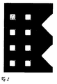
- the mask 1 images only the outer shape of the chip and has no further Structures on. It is used to create a 200 ⁇ m thick floor which is continued with the mask 2 shown in Figure 1.
- the layer arranged above the base surface is created by the mask 2.
- the mask 2 shows on the right side of the inlets 1 and 2 to a not yet recognizable inlet channel.
- the reaction chamber floors 3 to 10 already show the acute-angled walls 11, 12 (only exemplified) and the rounding 13 (only exemplary numbered) in the areas where the other walls abut each other.
- FIG. 2 shows the structures which can be provided in the mask 3.
- the shown Constrictions 14 and 15 start in the vertical direction about 100 microns from the ground. They thus form vertical rod-shaped elements, starting slightly from the ground.
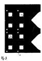
- FIG. 3 shows the overlying plane produced with the mask 4 becomes.
- a special cloverleaf-shaped training 16th (only quantified as an example) to see the connection in a higher level forms between vent and vent lines.
- Side walls have an open vertical channel and in upper area of the image delimiting a closed vertical channel.
- a channel cover 17 is in the upper area of the image educated.
- FIG. 4 shows the mask 5 used to produce the overlying mask Layer serves.
- the inlet channels 18 and 19 and to detect a vent passage 20.
- Both the inlet channels 18 and 19 as well as the venting channel 20 have a longitudinal pitch 21, 22 and 23, respectively on.
- the masks 3 and 4 are in Figures 2 and 3 without structured side walls represented the reaction chambers.
- FIG. 5 and that in FIG 6 show how the walls of the reaction chambers with a Zigzag structure 24 can be provided whose edges are perpendicular extend.
- mask 6 further worked.
- this mask are already distribution channels 25 between the reaction chambers 3 and the inlet channel 18th to recognize.
- the inlet channel 18 is closed on the left, cut side and the vent passage 20 is open on the left, cut side.
Landscapes
- Chemical & Material Sciences (AREA)
- Health & Medical Sciences (AREA)
- General Health & Medical Sciences (AREA)
- Analytical Chemistry (AREA)
- Clinical Laboratory Science (AREA)
- Hematology (AREA)
- Chemical Kinetics & Catalysis (AREA)
- Dispersion Chemistry (AREA)
- Physics & Mathematics (AREA)
- Life Sciences & Earth Sciences (AREA)
- Biochemistry (AREA)
- General Physics & Mathematics (AREA)
- Immunology (AREA)
- Pathology (AREA)
- Apparatus Associated With Microorganisms And Enzymes (AREA)
Applications Claiming Priority (2)
| Application Number | Priority Date | Filing Date | Title |
|---|---|---|---|
| DE10351943 | 2003-11-07 | ||
| DE10351943 | 2003-11-07 |
Publications (2)
| Publication Number | Publication Date |
|---|---|
| EP1529567A2 true EP1529567A2 (fr) | 2005-05-11 |
| EP1529567A3 EP1529567A3 (fr) | 2005-05-25 |
Family
ID=34428588
Family Applications (1)
| Application Number | Title | Priority Date | Filing Date |
|---|---|---|---|
| EP04024263A Withdrawn EP1529567A3 (fr) | 2003-11-07 | 2004-10-12 | Porte échantillon avec chambre de reaction |
Country Status (1)
| Country | Link |
|---|---|
| EP (1) | EP1529567A3 (fr) |
Citations (1)
| Publication number | Priority date | Publication date | Assignee | Title |
|---|---|---|---|---|
| WO1999046045A1 (fr) | 1998-03-11 | 1999-09-16 | MICROPARTS GESELLSCHAFT FüR MIKROSTRUKTURTECHNIK MBH | Porte-echantillon |
Family Cites Families (2)
| Publication number | Priority date | Publication date | Assignee | Title |
|---|---|---|---|---|
| CA2158340A1 (fr) * | 1993-03-16 | 1994-09-29 | Robert Edward Burrell | Plaque a microtitration amelioree et immuno-essais effectues a l'interieur de cette plaque |
| GB0122286D0 (en) * | 2001-09-14 | 2001-11-07 | Scient Generics Ltd | Optical coatings for high-throughput laboratory consumables |
-
2004
- 2004-10-12 EP EP04024263A patent/EP1529567A3/fr not_active Withdrawn
Patent Citations (1)
| Publication number | Priority date | Publication date | Assignee | Title |
|---|---|---|---|---|
| WO1999046045A1 (fr) | 1998-03-11 | 1999-09-16 | MICROPARTS GESELLSCHAFT FüR MIKROSTRUKTURTECHNIK MBH | Porte-echantillon |
Also Published As
| Publication number | Publication date |
|---|---|
| EP1529567A3 (fr) | 2005-05-25 |
Similar Documents
| Publication | Publication Date | Title |
|---|---|---|
| EP1013341B1 (fr) | Dispositif de drainage d'un liquide hors d'un capillaire | |
| EP0765683B1 (fr) | Appareil de traitement de liquides, en particulier du sang | |
| DE69615655T2 (de) | Biologische analytische vorrichtung mit verbesserter verhinderung von kontamination | |
| DE69322995T2 (de) | Pressbiegeverfahren und Vorrichtung zum Biegen von Glasscheiben | |
| DE3783880T2 (de) | Strukturierte kolonnenpackung. | |
| DE19908171A1 (de) | Kontinuierliches Herstellungsverfahren für Mikrokugeln und Vorrichtung hierfür | |
| WO1999046045A1 (fr) | Porte-echantillon | |
| DE899345C (de) | Kolonnenboden und Verfahren zu dessen Herstellung | |
| DE10109958C1 (de) | Gekühlte Kalibriervorrichtung für eine Kunststoffextrusionsanlage | |
| DE102020107599B3 (de) | Verfahren zur Kultivierung von Zellen | |
| DE1937332C3 (de) | Verfahren und Vorrichtung zum Umwälzen der Flüssigkeit auf Austauschböden in Stoffaustauschkolonnen | |
| DE69912030T2 (de) | Luftkühlungsanordnung eines Raumes | |
| DE69928630T2 (de) | Einwegvorrichtung für eine Thorax-Drainage anschliessbar an eine Saugeinheit | |
| EP2143691A2 (fr) | Bioréacteur à membrane et procédé destinés au traitement d'eaux usées | |
| DE102004031424A1 (de) | Mikrochemischer Chip und Verfahren zu dessen Herstellung | |
| DE102020120644A1 (de) | Verfahren und Vorrichtung zum Herstellen eines mehrere Gewebeproben enthaltenden Gewebeblocks in einem einzigen Ausgießschritt | |
| DE2616395A1 (de) | Vorrichtung zum einleiten eines gases in eine fluessigkeit | |
| DE102014109468B3 (de) | Kulturkammervorrichtung zur Erzeugung von flusslosen und zeitstabilen Gradienten | |
| DE2311575A1 (de) | Umwaelzvorrichtung fuer aquarien | |
| DE102008031220A1 (de) | Hybridkühlturm | |
| DE102014113343B4 (de) | Verfahren und struktur zum erzeugen von kavitäten mit extremen seitenverhältnissen | |
| DE102023125347B3 (de) | Mikrosystembauelement | |
| EP4149336B1 (fr) | Sac d'élimination à matrice de compensation de pression | |
| DE69007479T2 (de) | Druckformierleiste. | |
| DE8416418U1 (de) | Saugkörper mit einer mittleren Perforationsöffnung für Vorrichtungen zur Zellsedimentierung und insbesondere Liquorsedimentierung |
Legal Events
| Date | Code | Title | Description |
|---|---|---|---|
| PUAI | Public reference made under article 153(3) epc to a published international application that has entered the european phase |
Free format text: ORIGINAL CODE: 0009012 |
|
| PUAL | Search report despatched |
Free format text: ORIGINAL CODE: 0009013 |
|
| AK | Designated contracting states |
Kind code of ref document: A2 Designated state(s): AT BE BG CH CY CZ DE DK EE ES FI FR GB GR HU IE IT LI LU MC NL PL PT RO SE SI SK TR |
|
| AX | Request for extension of the european patent |
Extension state: AL HR LT LV MK |
|
| AK | Designated contracting states |
Kind code of ref document: A3 Designated state(s): AT BE BG CH CY CZ DE DK EE ES FI FR GB GR HU IE IT LI LU MC NL PL PT RO SE SI SK TR |
|
| AX | Request for extension of the european patent |
Extension state: AL HR LT LV MK |
|
| 17P | Request for examination filed |
Effective date: 20051125 |
|
| AKX | Designation fees paid |
Designated state(s): AT BE BG CH CY CZ DE DK EE ES FI FR GB GR HU IE IT LI LU MC NL PL PT RO SE SI SK TR |
|
| 17Q | First examination report despatched |
Effective date: 20081010 |
|
| STAA | Information on the status of an ep patent application or granted ep patent |
Free format text: STATUS: THE APPLICATION IS DEEMED TO BE WITHDRAWN |
|
| 18D | Application deemed to be withdrawn |
Effective date: 20100914 |