EP1529659A2 - Pneumatique pour véhicules - Google Patents
Pneumatique pour véhicules Download PDFInfo
- Publication number
- EP1529659A2 EP1529659A2 EP04104619A EP04104619A EP1529659A2 EP 1529659 A2 EP1529659 A2 EP 1529659A2 EP 04104619 A EP04104619 A EP 04104619A EP 04104619 A EP04104619 A EP 04104619A EP 1529659 A2 EP1529659 A2 EP 1529659A2
- Authority
- EP
- European Patent Office
- Prior art keywords
- incisions
- pneumatic vehicle
- vehicle tire
- tire according
- shoulder block
- Prior art date
- Legal status (The legal status is an assumption and is not a legal conclusion. Google has not performed a legal analysis and makes no representation as to the accuracy of the status listed.)
- Granted
Links
- 239000011295 pitch Substances 0.000 claims description 15
- 230000002093 peripheral effect Effects 0.000 description 5
- 101000912561 Bos taurus Fibrinogen gamma-B chain Proteins 0.000 description 1
- 230000001154 acute effect Effects 0.000 description 1
- 230000003247 decreasing effect Effects 0.000 description 1
- 238000005096 rolling process Methods 0.000 description 1
- 238000000926 separation method Methods 0.000 description 1
Images


Classifications
-
- B—PERFORMING OPERATIONS; TRANSPORTING
- B60—VEHICLES IN GENERAL
- B60C—VEHICLE TYRES; TYRE INFLATION; TYRE CHANGING; CONNECTING VALVES TO INFLATABLE ELASTIC BODIES IN GENERAL; DEVICES OR ARRANGEMENTS RELATED TO TYRES
- B60C11/00—Tyre tread bands; Tread patterns; Anti-skid inserts
- B60C11/03—Tread patterns
- B60C11/12—Tread patterns characterised by the use of narrow slits or incisions, e.g. sipes
- B60C11/1272—Width of the sipe
- B60C11/1281—Width of the sipe different within the same sipe, i.e. enlarged width portion at sipe bottom or along its length
-
- B—PERFORMING OPERATIONS; TRANSPORTING
- B60—VEHICLES IN GENERAL
- B60C—VEHICLE TYRES; TYRE INFLATION; TYRE CHANGING; CONNECTING VALVES TO INFLATABLE ELASTIC BODIES IN GENERAL; DEVICES OR ARRANGEMENTS RELATED TO TYRES
- B60C11/00—Tyre tread bands; Tread patterns; Anti-skid inserts
- B60C11/03—Tread patterns
- B60C11/0304—Asymmetric patterns
-
- B—PERFORMING OPERATIONS; TRANSPORTING
- B60—VEHICLES IN GENERAL
- B60C—VEHICLE TYRES; TYRE INFLATION; TYRE CHANGING; CONNECTING VALVES TO INFLATABLE ELASTIC BODIES IN GENERAL; DEVICES OR ARRANGEMENTS RELATED TO TYRES
- B60C11/00—Tyre tread bands; Tread patterns; Anti-skid inserts
- B60C11/03—Tread patterns
- B60C11/12—Tread patterns characterised by the use of narrow slits or incisions, e.g. sipes
-
- B—PERFORMING OPERATIONS; TRANSPORTING
- B60—VEHICLES IN GENERAL
- B60C—VEHICLE TYRES; TYRE INFLATION; TYRE CHANGING; CONNECTING VALVES TO INFLATABLE ELASTIC BODIES IN GENERAL; DEVICES OR ARRANGEMENTS RELATED TO TYRES
- B60C11/00—Tyre tread bands; Tread patterns; Anti-skid inserts
- B60C11/03—Tread patterns
- B60C11/13—Tread patterns characterised by the groove cross-section, e.g. for buttressing or preventing stone-trapping
-
- B—PERFORMING OPERATIONS; TRANSPORTING
- B60—VEHICLES IN GENERAL
- B60C—VEHICLE TYRES; TYRE INFLATION; TYRE CHANGING; CONNECTING VALVES TO INFLATABLE ELASTIC BODIES IN GENERAL; DEVICES OR ARRANGEMENTS RELATED TO TYRES
- B60C11/00—Tyre tread bands; Tread patterns; Anti-skid inserts
- B60C11/03—Tread patterns
- B60C11/13—Tread patterns characterised by the groove cross-section, e.g. for buttressing or preventing stone-trapping
- B60C11/1307—Tread patterns characterised by the groove cross-section, e.g. for buttressing or preventing stone-trapping with special features of the groove walls
- B60C11/1323—Tread patterns characterised by the groove cross-section, e.g. for buttressing or preventing stone-trapping with special features of the groove walls asymmetric
-
- B—PERFORMING OPERATIONS; TRANSPORTING
- B60—VEHICLES IN GENERAL
- B60C—VEHICLE TYRES; TYRE INFLATION; TYRE CHANGING; CONNECTING VALVES TO INFLATABLE ELASTIC BODIES IN GENERAL; DEVICES OR ARRANGEMENTS RELATED TO TYRES
- B60C11/00—Tyre tread bands; Tread patterns; Anti-skid inserts
- B60C11/03—Tread patterns
- B60C2011/0337—Tread patterns characterised by particular design features of the pattern
- B60C2011/0339—Grooves
- B60C2011/0358—Lateral grooves, i.e. having an angle of 45 to 90 degees to the equatorial plane
- B60C2011/0365—Lateral grooves, i.e. having an angle of 45 to 90 degees to the equatorial plane characterised by width
-
- B—PERFORMING OPERATIONS; TRANSPORTING
- B60—VEHICLES IN GENERAL
- B60C—VEHICLE TYRES; TYRE INFLATION; TYRE CHANGING; CONNECTING VALVES TO INFLATABLE ELASTIC BODIES IN GENERAL; DEVICES OR ARRANGEMENTS RELATED TO TYRES
- B60C11/00—Tyre tread bands; Tread patterns; Anti-skid inserts
- B60C11/03—Tread patterns
- B60C2011/0337—Tread patterns characterised by particular design features of the pattern
- B60C2011/0339—Grooves
- B60C2011/0374—Slant grooves, i.e. having an angle of about 5 to 35 degrees to the equatorial plane
-
- B—PERFORMING OPERATIONS; TRANSPORTING
- B60—VEHICLES IN GENERAL
- B60C—VEHICLE TYRES; TYRE INFLATION; TYRE CHANGING; CONNECTING VALVES TO INFLATABLE ELASTIC BODIES IN GENERAL; DEVICES OR ARRANGEMENTS RELATED TO TYRES
- B60C11/00—Tyre tread bands; Tread patterns; Anti-skid inserts
- B60C11/03—Tread patterns
- B60C2011/0337—Tread patterns characterised by particular design features of the pattern
- B60C2011/0339—Grooves
- B60C2011/0381—Blind or isolated grooves
-
- B—PERFORMING OPERATIONS; TRANSPORTING
- B60—VEHICLES IN GENERAL
- B60C—VEHICLE TYRES; TYRE INFLATION; TYRE CHANGING; CONNECTING VALVES TO INFLATABLE ELASTIC BODIES IN GENERAL; DEVICES OR ARRANGEMENTS RELATED TO TYRES
- B60C11/00—Tyre tread bands; Tread patterns; Anti-skid inserts
- B60C11/03—Tread patterns
- B60C11/12—Tread patterns characterised by the use of narrow slits or incisions, e.g. sipes
- B60C11/1204—Tread patterns characterised by the use of narrow slits or incisions, e.g. sipes with special shape of the sipe
- B60C2011/1213—Tread patterns characterised by the use of narrow slits or incisions, e.g. sipes with special shape of the sipe sinusoidal or zigzag at the tread surface
-
- B—PERFORMING OPERATIONS; TRANSPORTING
- B60—VEHICLES IN GENERAL
- B60C—VEHICLE TYRES; TYRE INFLATION; TYRE CHANGING; CONNECTING VALVES TO INFLATABLE ELASTIC BODIES IN GENERAL; DEVICES OR ARRANGEMENTS RELATED TO TYRES
- B60C11/00—Tyre tread bands; Tread patterns; Anti-skid inserts
- B60C11/03—Tread patterns
- B60C11/12—Tread patterns characterised by the use of narrow slits or incisions, e.g. sipes
- B60C11/1204—Tread patterns characterised by the use of narrow slits or incisions, e.g. sipes with special shape of the sipe
- B60C2011/1227—Tread patterns characterised by the use of narrow slits or incisions, e.g. sipes with special shape of the sipe having different shape within the pattern
-
- B—PERFORMING OPERATIONS; TRANSPORTING
- B60—VEHICLES IN GENERAL
- B60C—VEHICLE TYRES; TYRE INFLATION; TYRE CHANGING; CONNECTING VALVES TO INFLATABLE ELASTIC BODIES IN GENERAL; DEVICES OR ARRANGEMENTS RELATED TO TYRES
- B60C11/00—Tyre tread bands; Tread patterns; Anti-skid inserts
- B60C11/03—Tread patterns
- B60C11/12—Tread patterns characterised by the use of narrow slits or incisions, e.g. sipes
- B60C11/1204—Tread patterns characterised by the use of narrow slits or incisions, e.g. sipes with special shape of the sipe
- B60C2011/1231—Tread patterns characterised by the use of narrow slits or incisions, e.g. sipes with special shape of the sipe being shallow, i.e. sipe depth of less than 3 mm
-
- B—PERFORMING OPERATIONS; TRANSPORTING
- B60—VEHICLES IN GENERAL
- B60C—VEHICLE TYRES; TYRE INFLATION; TYRE CHANGING; CONNECTING VALVES TO INFLATABLE ELASTIC BODIES IN GENERAL; DEVICES OR ARRANGEMENTS RELATED TO TYRES
- B60C11/00—Tyre tread bands; Tread patterns; Anti-skid inserts
- B60C11/03—Tread patterns
- B60C11/12—Tread patterns characterised by the use of narrow slits or incisions, e.g. sipes
- B60C2011/129—Sipe density, i.e. the distance between the sipes within the pattern
- B60C2011/1295—Sipe density, i.e. the distance between the sipes within the pattern variable
Definitions
- the invention relates to a pneumatic vehicle tire for use in wintry Driving conditions with a tread, which by circumferential grooves, transverse grooves, Grooves and the like is divided into profile positive and in which one of the Circumferential grooves divides the tread into two differently shaped areas, one, related to the vehicle, with the tire mounted outside Outer portion and an inner portion, wherein the shoulder side one by Quernuten articulated block row is provided, and where the profile is positive each with a plurality of at least substantially in the transverse direction running incisions are provided.
- a tire with such a Tread pattern is known for example from DE 197 53 819 A1.
- This Tires are the profile positives in the outer area, this is the area of the tire, which faces the outside when the tire is mounted, with a higher one Transverse shear stiffness formed as the profile positive in the interior.
- the interior of the tread is for handling less important, but has meaning in terms of grip on ice, snow and Wetness should therefore have less stiff profile positive.
- the invention is therefore based on the object, a tire of the above mentioned type with respect to its handling characteristics on dry roads and its winter properties to further improve or optimize.
- the object is achieved according to the invention in that the transverse grooves in the shoulder block row of the outside area, in corresponding pitches considered narrower than those in the shoulder block row of the inner area, that the width of the shoulder block row of the outer area is greater than the width the shoulder block row of the inner area that the mutual distance of Incisions in the blocks of the shoulder block row of the outer area is larger as the distance of the incisions in the blocks of the shoulder block row of the Inside and that the cuts in the blocks of the shoulder block row of the Outside are narrower than the cuts in the blocks of the Shoulder block row of the interior area.
- the combination of these measures causes the exterior of the Tread in terms of handling characteristics on dry roads is optimized by specifically increasing the stiffness in this area and on particularly advantageous manner is influenced, and that in the tread interior area Compared to the exterior a much softer structural design outweighs that in terms of grip properties on winter and wet Roadways is optimized.
- tread pattern can be explained by some improve concrete measures particularly well.
- One of these measures is that the width of the transverse grooves in the shoulder block row of the inner area to at least 2% larger than the width of the transverse grooves in the Shoulder block row of the outside area.
- Another measure provides that the width of the shoulder block row of the Exterior is at least 10% larger than the number of Shoulder block row of the interior area.
- the width of the cuts in the blocks of the Shoulder block row of the outdoor area should be at least 20% less than the Width of the cuts in the blocks of the shoulder block row of the inner area.
- main incisions specially designed by main incisions be provided, which with at least two mutually in the one and the Other circumferentially facing side incisions are provided, the no Connect to other cuts, with the adjacent ones Main incisions with respect to the orientation direction of the branching Secondary incisions are executed consistently.
- the cuts in the profile positive in the outdoor area are preferably waves or sinusoidal, the amplitude of the waveform of the cuts in one of the extension directions of the incisions increases.
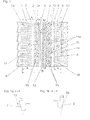
- the tread patterns shown in Figs. 1 and 4 are over the width B of Tire viewed in the ground contact patch. Both tread profiles are axial divided into two functionally different areas A and I.
- the outdoor area A is the area which, in the case of tires mounted on the vehicle, at the Vehicle outside should be and is constructive in terms of optimum Dry properties of the tread pattern designed.
- the interior of the I Tread is specially designed for good winter grip properties.
- the tread pattern shown in Figure 1 belong to the Tread outer region A forming profile positive a shoulder block row 1 and a tread band 2, to the profile positive, which form the inner region I, include a structured by diagonal grooves 4 peripheral region 3 and a second Shoulder block row 5.
- the band 2 is from the peripheral area by a straight in Circumferentially circumferential groove 6 separated. Further circumferential grooves 7, 8 adjoin the shoulder block rows 1, 5.
- the interior I of the tread located circumferential groove 8 is the widest of all circumferential grooves 6, 7, 8.
- the Separation between inner area I and outer area A is carried out by the Circumferential groove 6, which is offset from the center circumference line M-M to the outside is such that the outer portion A about 40% of the width B of the ground contact patch occupies.
- the tread band 2 is defined by blind grooves 2a, which are of the circumferential groove 6 go out and at an angle of about 60 ° to the circumferential direction, structured.
- the shoulder block rows 1, 5 have blocks 1a, 5a, through Transverse grooves 9, 10 are separated from each other.
- the profile positive are by the blind grooves 2a, the diagonal grooves 4 and the Transverse grooves 6, 10 in substantially the same, in the tire circumferential direction successive profile sections, so-called pitches, articulated. pitches usually turn into two to five different pitch sequences Circumferential lengths provided to optimize the rolling noise.
- the number of pitches the outside pitch A of the track is smaller than the number of pitches in the track Interior I.
- the difference in the number of pitches between outdoor area A too Interior I is between 7% and 12%.
- the Pitch number in the outdoor area 62 and indoor 68 This is in the Interior I over the circumference more and circumferentially shorter profile positive formed as in the outer area A.
- the higher number of transverse grooves 10 in Interior I provides more edges than outside A.
- transverse grooves 9, 10 Both in the outdoor area A as well as in the interior I running Shoulder block row 1, 5 are the transverse grooves 9, 10 with different widths, in Dependence on the circumferential length of the pitch - in shorter pitches Narrower, in longer running pitches wider transverse grooves 9, 10 - executed.
- the width a of the shoulder block row 1 in the outer portion A is also greater than that Width b of the shoulder block row 5 in the inner section I.
- the shoulder block row 1 is at least 10% wider than the shoulder block row 5.
- the peripheral region 3 is defined by the diagonal grooves 4, which starting from the Circumferential groove 8 under a decreasing to the circumferential direction pitch angle run and oriented more in the circumferential direction than in the transverse direction, as well as by oppositely extending to the grooves 4 connecting grooves 11 in blocks 12th and a comparatively narrow band 13 articulated.
- All profile are positive by a variety of in the transverse direction or in the Structured essentially in the transverse direction incisions.
- the cuts have a width between 0.4 mm and 0.8 mm and a depth between 1.5 mm and Dessintiefe, which is usually between 7 mm and 9 mm, on.
- in the Inside section I of the tread are in the shoulder blocks 5a, as appropriate Pitch length, two or three parallel to the transverse grooves 10 oriented cuts 14th provided, consisting of undulating and substantially straight Put sections together.
- Running parallel to each other and analogous to The incisions 14 executed incisions 15 are also in the peripheral region. 3 intended.
- In the circumferential direction adjacent cuts 14, 15 are largely by a respective circumferential connection cut 14a connected.
- Fig. 1a and 1b show cross-sections through the adjoining the shoulder block rows 1, 5 circumferential grooves 7 and 8. Tread inside the flanks of the circumferential grooves 7, 8 extend approximately in the radial direction. The second flank of the circumferential groove 8 extends at an angle alpha 2 of about 6 ° to the radial direction.
- 1a shows the cross section through the adjoining the shoulder block row 1 circumferential groove 7, which also has an asymmetrical cross-section.
- the flank of the circumferential groove 7 formed by the shoulder blocks 1a extends at an angle alpha 1 to the radial direction, which is greater by at least 5 ° than the angle alpha 2 of the block flanks which bound the circumferential groove 8.
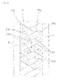
- the notches 17, 18 provided in the profile positive in the outer region A are designed to be sinusoidal or wave-shaped in a special way.
- the waveform is shown in particular in FIGS. 2 and 3.
- At least the amplitude, but in particular also the wavelength of the cuts 17 increases in one direction, with the incisions 17 with increasing distance from the tread edge toward the circumferential groove 7. This increase can be continuous or stepwise.
- the waves of the cuts 17 at least two different amplitudes.
- FIG. 3 shows an incision 17 with three different amplitudes c 1 , c 2 , c 3 .
- the waves In the region of the tread edge, the waves have the smallest amplitude c 3 , which is between 35% and 60% of the largest amplitude c 1 , which is present in the region of one or more waves at the other end of the notch 17.
- the wavy incision 17 has an amplitude c 2 of average size over at least one wavelength, which is between 65% and 85% of the largest amplitude c 1 .
- the amplitude c 1 is of the order of 1 to 2 mm. With the amplitude preferably also increases the wavelength.
- the largest wavelength lambda 1 in the region of that wave or waves which have the largest amplitude c1 is at least twice the amplitude c 1
- the wavelength lambda 2 in the region of the wave with the average amplitude c 2 is at least twice the c 2
- for the wavelength ⁇ 3 with the smallest amplitude c 3 is also valid so that ⁇ 3 is at least twice that of C 3 .
- the mutual distance adjacent incisions 17 - defined as the mutual distance of the in Extending direction extending incision symmetry - is in the Shoulder blocks 1a in outdoor area A at least 10% larger than the corresponding mutual distance of the incisions 14 in the blocks 5a of Shoulder block row 5.
- the incisions 17 to at least 20% narrower than the cuts 14th
- the wavy cuts 18 are such executed that their amplitude starting from their one end, such as described above, increases.
- the wavelength of the Incisions 18, as described, can be varied.
- the orientation direction of the cuts 17 corresponds to the transverse direction, so that in the illustrated embodiment, the cuts 17 are not parallel to the slightly curved, but otherwise substantially transverse transverse grooves 9.
- the arranged in the tread band 2 cuts 18 are oriented at an acute angle beta 1 in the order of 20 ° to 40 ° to the transverse direction.
- the angle beta 1 is at most the same size, in particular smaller than beta 2 , which is the angle which the incisions 15 enclose in the peripheral region 3 with the transverse direction.
- the outside area A is very similar to Outside area A of the embodiment shown in Fig. 1 executed. This concerns especially the design of the shoulder block row 1 ', the shoulder blocks 1'a and the tread band 2 ', the provision of two wide circumferential grooves 6', 7 'and the execution of the cuts 17 'and 18'.
- the orientation of the blind grooves 2'a and the cuts 18 'in the band 2' is in the opposite direction to that of the blind grooves 2a and the cuts 18 in the first embodiment.
- Tread bands 20, 21 are provided which are structured by blind grooves 20a, 21a are.
- the two tread bands 20, 21 are defined by a wide circumferential groove 8 " separated from each other.
- the shoulder block row 5 'in the inner area I is characterized by in Transverse direction and straight transverse grooves 10 'in blocks 5'a articulated.
- the Tread bands 20, 21 and the blocks 5'a of the shoulder block row 5 ' are with specially designed incisions, which in the following with reference to FIG. 5, which shows an enlarged view of a top view of a detail of FIG Tread band 20 shows, described in more detail.
- the main cuts 22 are essentially in Oriented transversely, such that the angle gamma is at least 45 °, in particular at least 55 °, is selected.
- Between two in the circumferential direction adjacent blind grooves 20a are at least two, as shown in FIG. 5 are four According to the invention carried out main incisions 22.
- the mutual Arrangement of the cuts 22 is such that they are alternately from the one and the other circumferential groove 6, 8 "go out and in one, based on the width of the Bandes 20, relatively small distance of 5 to 20% of the width of the Tread band ends in front of the other circumferential groove.
- each main cut 22 branch off straight sub-cuts 23a, 23b.
- the one side cut 23a has in the one circumferential direction, the other Second cut 23b in the other circumferential direction.
- the angle gamma 'between an incision 22 and the secondary incisions 23a, 23b is preferably a right one Angle, it is in particular in the order of 80 ° and 100 °.
- at all four main cuts 22 branch the siding 23 a and the Secondary incisions 23b in matching directions and under matching angles from the main incisions 22.
- Both the Start points and the end points of all sidelines 23a, 23b lie in the illustrated embodiment, on lines parallel to the respective block edge run.
- all Secondary cuts 23a, 23b made the same length.
- the length I of the sneezes 23a, 23b is preferably between 45% and 55% of the normal distance n of adjacent main cuts 22.
- the two secondary cuts 23a, 23b of a Schoeinschnittes 22 have a mutual distance, at least the Distance n corresponds, but is preferably greater than n.
- the blind grooves 20a are parallel to the main incisions 22 extending further incisions 22a set, of which, parallel to the Sack grooves 20a, extending in the direction of circumferential groove cuts 24, the wider than the cuts 22 and can also be replaced by grooves.
- Further short cuts 22b are provided parallel to the cuts 22a.
- the cuts 22a, 22b are in accordance with the orientation and Arrangement of the secondary incisions 23a, 23b, each with a secondary incision 23c Mistake. Arrangement and execution of the secondary cuts 23c are to the Adjacent cuts 23a, 23b adapted accordingly.
- each shoulder block 5'a has either two or three parallel to the Transverse grooves 10 'extending and from the circumferential groove 8' outgoing Main cuts 25, which with secondary cuts 26a, 26b, of the Main incisions 25 alternately in one and in the other circumferential direction branch off, are provided.
- the cuts 25 can also be such in the each block 5'a be arranged, that alternately an incision 25 in the Circumferential groove 8 'opens and the other already before the circumferential groove 8' ends.
- the widths a, b of the shoulder block rows 1'a, 5'a in the outer area A the mutual distances of and the width of the incisions in the outer and inner areas A, I, the width of the transverse grooves 9 ', 10', the flank angles the circumferential grooves 7 ', 8' as well as the angles beta 1 and beta 2 apply to the above details of the embodiment according to FIG. 1.
- the invention is not limited to the illustrated embodiments, In particular, it is possible, according to the invention running treads with to combine differently shaped cuts.
Landscapes
- Engineering & Computer Science (AREA)
- Mechanical Engineering (AREA)
- Tires In General (AREA)
Applications Claiming Priority (2)
| Application Number | Priority Date | Filing Date | Title |
|---|---|---|---|
| DE10352149A DE10352149A1 (de) | 2003-11-04 | 2003-11-04 | Fahrzeugluftreifen |
| DE10352149 | 2003-11-04 |
Publications (3)
| Publication Number | Publication Date |
|---|---|
| EP1529659A2 true EP1529659A2 (fr) | 2005-05-11 |
| EP1529659A3 EP1529659A3 (fr) | 2005-06-15 |
| EP1529659B1 EP1529659B1 (fr) | 2011-11-16 |
Family
ID=34428614
Family Applications (1)
| Application Number | Title | Priority Date | Filing Date |
|---|---|---|---|
| EP04104619A Expired - Lifetime EP1529659B1 (fr) | 2003-11-04 | 2004-09-23 | Pneumatique pour véhicules |
Country Status (3)
| Country | Link |
|---|---|
| EP (1) | EP1529659B1 (fr) |
| AT (1) | ATE533646T1 (fr) |
| DE (1) | DE10352149A1 (fr) |
Cited By (18)
| Publication number | Priority date | Publication date | Assignee | Title |
|---|---|---|---|---|
| JP2007015511A (ja) * | 2005-07-06 | 2007-01-25 | Yokohama Rubber Co Ltd:The | 空気入りタイヤ |
| WO2007065760A1 (fr) * | 2005-12-06 | 2007-06-14 | Continental Aktiengesellschaft | Profil de bande de roulement a lamelles sinusoidales |
| WO2008026255A1 (fr) * | 2006-08-29 | 2008-03-06 | The Yokohama Rubber Co., Ltd. | Pneumatique |
| EP2113399A1 (fr) | 2008-04-28 | 2009-11-04 | The Yokohama Rubber Co., Ltd. | Pneu |
| RU2389610C1 (ru) * | 2006-08-29 | 2010-05-20 | Дзэ Йокогама Рабер Ко., Лтд. | Пневматическая шина |
| EP2199111A2 (fr) | 2008-12-22 | 2010-06-23 | Sumtiomo Rubber Industries Ltd | Pneu avec lamelles |
| US20110297284A1 (en) * | 2008-12-10 | 2011-12-08 | Stefano Montesello | Pneumatic tyre |
| US20130081744A1 (en) * | 2011-10-04 | 2013-04-04 | The Yokohama Rubber Co., Ltd | Pneumatic Tire |
| CN103029526A (zh) * | 2011-10-07 | 2013-04-10 | 住友橡胶工业株式会社 | 充气轮胎 |
| CN103101403A (zh) * | 2011-11-14 | 2013-05-15 | 横滨橡胶株式会社 | 充气轮胎 |
| CN106103140A (zh) * | 2014-03-07 | 2016-11-09 | 普利司通美国轮胎运营有限责任公司 | 以刀槽花纹为特色的轮胎胎面 |
| CN107074029A (zh) * | 2014-09-11 | 2017-08-18 | 株式会社普利司通 | 充气轮胎 |
| US20180056726A1 (en) * | 2016-08-31 | 2018-03-01 | Sumitomo Rubber Industries, Ltd. | Tire |
| WO2018103925A1 (fr) * | 2016-12-07 | 2018-06-14 | Continental Reifen Deutschland Gmbh | Pneumatique de véhicule |
| JP2019209732A (ja) * | 2018-05-31 | 2019-12-12 | 住友ゴム工業株式会社 | タイヤ |
| CN112622530A (zh) * | 2019-10-08 | 2021-04-09 | 住友橡胶工业株式会社 | 轮胎 |
| US11285762B2 (en) * | 2018-05-29 | 2022-03-29 | Sumitomo Rubber Industries, Ltd. | Tyre |
| FR3140305A1 (fr) * | 2022-10-03 | 2024-04-05 | Compagnie Generale Des Etablissements Michelin | Pneumatique comprenant une bande de roulement à usure homogène |
Families Citing this family (2)
| Publication number | Priority date | Publication date | Assignee | Title |
|---|---|---|---|---|
| DE102008029659A1 (de) | 2008-06-24 | 2009-12-31 | Continental Aktiengesellschaft | Fahrzeugluftreifen |
| DE102008029658A1 (de) | 2008-06-24 | 2009-12-31 | Continental Aktiengesellschaft | Fahrzeugluftreifen |
Citations (3)
| Publication number | Priority date | Publication date | Assignee | Title |
|---|---|---|---|---|
| EP0420834A1 (fr) | 1989-09-26 | 1991-04-03 | Semperit Reifen Aktiengesellschaft | Bandage pneumatique pour véhicules |
| EP0428472A2 (fr) | 1989-11-15 | 1991-05-22 | The Goodyear Tire & Rubber Company | Pneumatique asymétrique |
| DE19753819A1 (de) | 1997-12-04 | 1999-06-17 | Continental Ag | Winterreifenprofil |
Family Cites Families (1)
| Publication number | Priority date | Publication date | Assignee | Title |
|---|---|---|---|---|
| DE19650655C2 (de) * | 1996-12-06 | 2000-08-24 | Continental Ag | Fahrzeugreifen mit Einschnitten im Laufstreifen |
-
2003
- 2003-11-04 DE DE10352149A patent/DE10352149A1/de not_active Withdrawn
-
2004
- 2004-09-23 EP EP04104619A patent/EP1529659B1/fr not_active Expired - Lifetime
- 2004-09-23 AT AT04104619T patent/ATE533646T1/de active
Patent Citations (3)
| Publication number | Priority date | Publication date | Assignee | Title |
|---|---|---|---|---|
| EP0420834A1 (fr) | 1989-09-26 | 1991-04-03 | Semperit Reifen Aktiengesellschaft | Bandage pneumatique pour véhicules |
| EP0428472A2 (fr) | 1989-11-15 | 1991-05-22 | The Goodyear Tire & Rubber Company | Pneumatique asymétrique |
| DE19753819A1 (de) | 1997-12-04 | 1999-06-17 | Continental Ag | Winterreifenprofil |
Cited By (39)
| Publication number | Priority date | Publication date | Assignee | Title |
|---|---|---|---|---|
| JP2007015511A (ja) * | 2005-07-06 | 2007-01-25 | Yokohama Rubber Co Ltd:The | 空気入りタイヤ |
| WO2007065760A1 (fr) * | 2005-12-06 | 2007-06-14 | Continental Aktiengesellschaft | Profil de bande de roulement a lamelles sinusoidales |
| WO2008026255A1 (fr) * | 2006-08-29 | 2008-03-06 | The Yokohama Rubber Co., Ltd. | Pneumatique |
| RU2389610C1 (ru) * | 2006-08-29 | 2010-05-20 | Дзэ Йокогама Рабер Ко., Лтд. | Пневматическая шина |
| US8210222B2 (en) | 2006-08-29 | 2012-07-03 | The Yokohama Rubber Co., Ltd. | Pneumatic tire |
| EP2113399A1 (fr) | 2008-04-28 | 2009-11-04 | The Yokohama Rubber Co., Ltd. | Pneu |
| US9254719B2 (en) * | 2008-12-10 | 2016-02-09 | Pirelli Tyre S.P.A. | Pneumatic tire |
| US20110297284A1 (en) * | 2008-12-10 | 2011-12-08 | Stefano Montesello | Pneumatic tyre |
| EP2199111A3 (fr) * | 2008-12-22 | 2013-03-06 | Sumitomo Rubber Industries, Ltd. | Pneu avec lamelles |
| RU2508204C2 (ru) * | 2008-12-22 | 2014-02-27 | Сумитомо Раббер Индастриз, Лтд. | Пневматическая шина со щелевидными дренажными канавками |
| EP2199111A2 (fr) | 2008-12-22 | 2010-06-23 | Sumtiomo Rubber Industries Ltd | Pneu avec lamelles |
| US8578985B2 (en) | 2008-12-22 | 2013-11-12 | Sumitomo Rubber Industries, Ltd. | Pneumatic tire with sipes |
| US20130081744A1 (en) * | 2011-10-04 | 2013-04-04 | The Yokohama Rubber Co., Ltd | Pneumatic Tire |
| US10173472B2 (en) * | 2011-10-04 | 2019-01-08 | The Yokohama Rubber Co., Ltd. | Pneumatic tire |
| US20160368325A1 (en) * | 2011-10-04 | 2016-12-22 | The Yokohama Rubber Co., Ltd. | Pneumatic Tire |
| US9463670B2 (en) * | 2011-10-04 | 2016-10-11 | The Yokohama Rubber Co., Ltd. | Pneumatic tire |
| CN103029526B (zh) * | 2011-10-07 | 2016-02-24 | 住友橡胶工业株式会社 | 充气轮胎 |
| CN103029526A (zh) * | 2011-10-07 | 2013-04-10 | 住友橡胶工业株式会社 | 充气轮胎 |
| JP2013082308A (ja) * | 2011-10-07 | 2013-05-09 | Sumitomo Rubber Ind Ltd | 空気入りタイヤ |
| EP2578418A1 (fr) * | 2011-10-07 | 2013-04-10 | Sumitomo Rubber Industries Limited | Pneu |
| CN103101403A (zh) * | 2011-11-14 | 2013-05-15 | 横滨橡胶株式会社 | 充气轮胎 |
| US9421829B2 (en) * | 2011-11-14 | 2016-08-23 | The Yokohama Rubber Co., Ltd. | Pneumatic tire |
| US20130118663A1 (en) * | 2011-11-14 | 2013-05-16 | The Yokohama Rubber Co., Ltd. | Pneumatic Tire |
| CN106103140A (zh) * | 2014-03-07 | 2016-11-09 | 普利司通美国轮胎运营有限责任公司 | 以刀槽花纹为特色的轮胎胎面 |
| EP3113961A4 (fr) * | 2014-03-07 | 2017-11-29 | Bridgestone Americas Tire Operations, LLC | Bande de roulement présentant une lamelle |
| CN107074029A (zh) * | 2014-09-11 | 2017-08-18 | 株式会社普利司通 | 充气轮胎 |
| EP3192673A4 (fr) * | 2014-09-11 | 2017-08-30 | Bridgestone Corporation | Pneumatique |
| US11007820B2 (en) * | 2016-08-31 | 2021-05-18 | Sumitomo Rubber Industries, Ltd. | Tire |
| US20180056726A1 (en) * | 2016-08-31 | 2018-03-01 | Sumitomo Rubber Industries, Ltd. | Tire |
| WO2018103925A1 (fr) * | 2016-12-07 | 2018-06-14 | Continental Reifen Deutschland Gmbh | Pneumatique de véhicule |
| US11285762B2 (en) * | 2018-05-29 | 2022-03-29 | Sumitomo Rubber Industries, Ltd. | Tyre |
| JP2019209732A (ja) * | 2018-05-31 | 2019-12-12 | 住友ゴム工業株式会社 | タイヤ |
| CN112622530A (zh) * | 2019-10-08 | 2021-04-09 | 住友橡胶工业株式会社 | 轮胎 |
| EP3805018A1 (fr) * | 2019-10-08 | 2021-04-14 | Sumitomo Rubber Industries Limited | Pneumatique |
| EP4101658A1 (fr) * | 2019-10-08 | 2022-12-14 | Sumitomo Rubber Industries, Ltd. | Pneu |
| US11590805B2 (en) | 2019-10-08 | 2023-02-28 | Sumitomo Rubber Industries, Ltd. | Tire |
| CN112622530B (zh) * | 2019-10-08 | 2024-03-08 | 住友橡胶工业株式会社 | 轮胎 |
| FR3140305A1 (fr) * | 2022-10-03 | 2024-04-05 | Compagnie Generale Des Etablissements Michelin | Pneumatique comprenant une bande de roulement à usure homogène |
| WO2024074330A1 (fr) * | 2022-10-03 | 2024-04-11 | Compagnie Generale Des Etablissements Michelin | Pneumatique comprenant une bande de roulement à usure homogène et à bruit réduit |
Also Published As
| Publication number | Publication date |
|---|---|
| ATE533646T1 (de) | 2011-12-15 |
| EP1529659A3 (fr) | 2005-06-15 |
| EP1529659B1 (fr) | 2011-11-16 |
| DE10352149A1 (de) | 2005-06-02 |
Similar Documents
| Publication | Publication Date | Title |
|---|---|---|
| EP1529659B1 (fr) | Pneumatique pour véhicules | |
| EP2920007B1 (fr) | Pneumatique | |
| EP2193038B1 (fr) | Pneumatique pour véhicule | |
| EP0671288B1 (fr) | Bandage pneumatique pour véhicule | |
| EP2509803B1 (fr) | Profil de bande de roulement de pneumatique de véhicule | |
| EP2965925B1 (fr) | Pneumatiques de véhicule | |
| DE102007061148A1 (de) | Fahrzeugluftreifen | |
| DE102008037497A1 (de) | Fahrzeugluftreifen | |
| EP3383669B1 (fr) | Pneumatique de véhicule | |
| EP2159080A1 (fr) | Pneumatique | |
| EP0968847B1 (fr) | Bandage pneumatique pour véhicule | |
| EP1106393A2 (fr) | Bandage pneumatique pour véhicule | |
| DE102007051645A1 (de) | Fahrzeugluftreifen | |
| EP3383675B1 (fr) | Pneumatique de véhicule | |
| EP2138327B1 (fr) | Bande de roulement pour pneumatique | |
| DE19957914C2 (de) | Fahrzeugluftreifen | |
| EP1529662A1 (fr) | Bandage pneumatique pour véhicule | |
| EP2504180B1 (fr) | Pneu | |
| EP2138329B1 (fr) | Bande de roulement pour pneumatique | |
| EP3450213A1 (fr) | Pneumatique de véhicule | |
| DE19900266C2 (de) | Fahrzeugluftreifen mit einem laufrichtungsgebunden gestalteten Laufstreifenprofil | |
| EP2138328B1 (fr) | Pneus de véhicule | |
| DE102008037498A1 (de) | Fahrzeugluftreifen | |
| EP4577417A1 (fr) | Pneu de véhicule | |
| EP1080949B1 (fr) | Bandage pneumatique pour véhicule |
Legal Events
| Date | Code | Title | Description |
|---|---|---|---|
| PUAI | Public reference made under article 153(3) epc to a published international application that has entered the european phase |
Free format text: ORIGINAL CODE: 0009012 |
|
| PUAL | Search report despatched |
Free format text: ORIGINAL CODE: 0009013 |
|
| AK | Designated contracting states |
Kind code of ref document: A2 Designated state(s): AT BE BG CH CY CZ DE DK EE ES FI FR GB GR HU IE IT LI LU MC NL PL PT RO SE SI SK TR |
|
| AX | Request for extension of the european patent |
Extension state: AL HR LT LV MK |
|
| AK | Designated contracting states |
Kind code of ref document: A3 Designated state(s): AT BE BG CH CY CZ DE DK EE ES FI FR GB GR HU IE IT LI LU MC NL PL PT RO SE SI SK TR |
|
| AX | Request for extension of the european patent |
Extension state: AL HR LT LV MK |
|
| 17P | Request for examination filed |
Effective date: 20051215 |
|
| AKX | Designation fees paid |
Designated state(s): AT BE BG CH CY CZ DE DK EE ES FI FR GB GR HU IE IT LI LU MC NL PL PT RO SE SI SK TR |
|
| AXX | Extension fees paid |
Extension state: MK Payment date: 20051215 Extension state: LT Payment date: 20051215 Extension state: HR Payment date: 20051215 Extension state: LV Payment date: 20051215 Extension state: AL Payment date: 20051215 |
|
| RAP1 | Party data changed (applicant data changed or rights of an application transferred) |
Owner name: CONTINENTAL REIFEN DEUTSCHLAND GMBH |
|
| 17Q | First examination report despatched |
Effective date: 20100506 |
|
| RIC1 | Information provided on ipc code assigned before grant |
Ipc: B60C 11/12 20060101ALI20110621BHEP Ipc: B60C 11/03 20060101AFI20110621BHEP |
|
| GRAP | Despatch of communication of intention to grant a patent |
Free format text: ORIGINAL CODE: EPIDOSNIGR1 |
|
| GRAS | Grant fee paid |
Free format text: ORIGINAL CODE: EPIDOSNIGR3 |
|
| GRAA | (expected) grant |
Free format text: ORIGINAL CODE: 0009210 |
|
| AK | Designated contracting states |
Kind code of ref document: B1 Designated state(s): AT BE BG CH CY CZ DE DK EE ES FI FR GB GR HU IE IT LI LU MC NL PL PT RO SE SI SK TR |
|
| AX | Request for extension of the european patent |
Extension state: AL HR LT LV MK |
|
| REG | Reference to a national code |
Ref country code: GB Ref legal event code: FG4D Free format text: NOT ENGLISH |
|
| REG | Reference to a national code |
Ref country code: CH Ref legal event code: EP |
|
| REG | Reference to a national code |
Ref country code: IE Ref legal event code: FG4D Free format text: LANGUAGE OF EP DOCUMENT: GERMAN |
|
| REG | Reference to a national code |
Ref country code: DE Ref legal event code: R096 Ref document number: 502004013063 Country of ref document: DE Effective date: 20120112 |
|
| REG | Reference to a national code |
Ref country code: SE Ref legal event code: TRGR |
|
| REG | Reference to a national code |
Ref country code: NL Ref legal event code: VDEP Effective date: 20111116 |
|
| LTLA | Lt: lapse of european patent or patent extension | ||
| PG25 | Lapsed in a contracting state [announced via postgrant information from national office to epo] |
Ref country code: PL Free format text: LAPSE BECAUSE OF FAILURE TO SUBMIT A TRANSLATION OF THE DESCRIPTION OR TO PAY THE FEE WITHIN THE PRESCRIBED TIME-LIMIT Effective date: 20111116 Ref country code: SI Free format text: LAPSE BECAUSE OF FAILURE TO SUBMIT A TRANSLATION OF THE DESCRIPTION OR TO PAY THE FEE WITHIN THE PRESCRIBED TIME-LIMIT Effective date: 20111116 Ref country code: NL Free format text: LAPSE BECAUSE OF FAILURE TO SUBMIT A TRANSLATION OF THE DESCRIPTION OR TO PAY THE FEE WITHIN THE PRESCRIBED TIME-LIMIT Effective date: 20111116 Ref country code: GR Free format text: LAPSE BECAUSE OF FAILURE TO SUBMIT A TRANSLATION OF THE DESCRIPTION OR TO PAY THE FEE WITHIN THE PRESCRIBED TIME-LIMIT Effective date: 20120217 Ref country code: PT Free format text: LAPSE BECAUSE OF FAILURE TO SUBMIT A TRANSLATION OF THE DESCRIPTION OR TO PAY THE FEE WITHIN THE PRESCRIBED TIME-LIMIT Effective date: 20120316 |
|
| REG | Reference to a national code |
Ref country code: IE Ref legal event code: FD4D |
|
| PG25 | Lapsed in a contracting state [announced via postgrant information from national office to epo] |
Ref country code: CY Free format text: LAPSE BECAUSE OF FAILURE TO SUBMIT A TRANSLATION OF THE DESCRIPTION OR TO PAY THE FEE WITHIN THE PRESCRIBED TIME-LIMIT Effective date: 20111116 |
|
| PG25 | Lapsed in a contracting state [announced via postgrant information from national office to epo] |
Ref country code: SK Free format text: LAPSE BECAUSE OF FAILURE TO SUBMIT A TRANSLATION OF THE DESCRIPTION OR TO PAY THE FEE WITHIN THE PRESCRIBED TIME-LIMIT Effective date: 20111116 Ref country code: CZ Free format text: LAPSE BECAUSE OF FAILURE TO SUBMIT A TRANSLATION OF THE DESCRIPTION OR TO PAY THE FEE WITHIN THE PRESCRIBED TIME-LIMIT Effective date: 20111116 Ref country code: EE Free format text: LAPSE BECAUSE OF FAILURE TO SUBMIT A TRANSLATION OF THE DESCRIPTION OR TO PAY THE FEE WITHIN THE PRESCRIBED TIME-LIMIT Effective date: 20111116 Ref country code: DK Free format text: LAPSE BECAUSE OF FAILURE TO SUBMIT A TRANSLATION OF THE DESCRIPTION OR TO PAY THE FEE WITHIN THE PRESCRIBED TIME-LIMIT Effective date: 20111116 Ref country code: BG Free format text: LAPSE BECAUSE OF FAILURE TO SUBMIT A TRANSLATION OF THE DESCRIPTION OR TO PAY THE FEE WITHIN THE PRESCRIBED TIME-LIMIT Effective date: 20120216 Ref country code: IE Free format text: LAPSE BECAUSE OF FAILURE TO SUBMIT A TRANSLATION OF THE DESCRIPTION OR TO PAY THE FEE WITHIN THE PRESCRIBED TIME-LIMIT Effective date: 20111116 |
|
| PG25 | Lapsed in a contracting state [announced via postgrant information from national office to epo] |
Ref country code: IT Free format text: LAPSE BECAUSE OF FAILURE TO SUBMIT A TRANSLATION OF THE DESCRIPTION OR TO PAY THE FEE WITHIN THE PRESCRIBED TIME-LIMIT Effective date: 20111116 Ref country code: RO Free format text: LAPSE BECAUSE OF FAILURE TO SUBMIT A TRANSLATION OF THE DESCRIPTION OR TO PAY THE FEE WITHIN THE PRESCRIBED TIME-LIMIT Effective date: 20111116 |
|
| PLBE | No opposition filed within time limit |
Free format text: ORIGINAL CODE: 0009261 |
|
| STAA | Information on the status of an ep patent application or granted ep patent |
Free format text: STATUS: NO OPPOSITION FILED WITHIN TIME LIMIT |
|
| 26N | No opposition filed |
Effective date: 20120817 |
|
| REG | Reference to a national code |
Ref country code: DE Ref legal event code: R097 Ref document number: 502004013063 Country of ref document: DE Effective date: 20120817 |
|
| BERE | Be: lapsed |
Owner name: CONTINENTAL REIFEN DEUTSCHLAND G.M.B.H. Effective date: 20120930 |
|
| PG25 | Lapsed in a contracting state [announced via postgrant information from national office to epo] |
Ref country code: ES Free format text: LAPSE BECAUSE OF FAILURE TO SUBMIT A TRANSLATION OF THE DESCRIPTION OR TO PAY THE FEE WITHIN THE PRESCRIBED TIME-LIMIT Effective date: 20120227 Ref country code: MC Free format text: LAPSE BECAUSE OF NON-PAYMENT OF DUE FEES Effective date: 20120930 |
|
| GBPC | Gb: european patent ceased through non-payment of renewal fee |
Effective date: 20120923 |
|
| REG | Reference to a national code |
Ref country code: FR Ref legal event code: ST Effective date: 20130531 |
|
| PG25 | Lapsed in a contracting state [announced via postgrant information from national office to epo] |
Ref country code: BE Free format text: LAPSE BECAUSE OF NON-PAYMENT OF DUE FEES Effective date: 20120930 Ref country code: GB Free format text: LAPSE BECAUSE OF NON-PAYMENT OF DUE FEES Effective date: 20120923 |
|
| PG25 | Lapsed in a contracting state [announced via postgrant information from national office to epo] |
Ref country code: FR Free format text: LAPSE BECAUSE OF NON-PAYMENT OF DUE FEES Effective date: 20121001 |
|
| PGFP | Annual fee paid to national office [announced via postgrant information from national office to epo] |
Ref country code: AT Payment date: 20130911 Year of fee payment: 10 Ref country code: SE Payment date: 20130919 Year of fee payment: 10 Ref country code: CH Payment date: 20130919 Year of fee payment: 10 |
|
| PG25 | Lapsed in a contracting state [announced via postgrant information from national office to epo] |
Ref country code: TR Free format text: LAPSE BECAUSE OF FAILURE TO SUBMIT A TRANSLATION OF THE DESCRIPTION OR TO PAY THE FEE WITHIN THE PRESCRIBED TIME-LIMIT Effective date: 20111116 |
|
| PG25 | Lapsed in a contracting state [announced via postgrant information from national office to epo] |
Ref country code: LU Free format text: LAPSE BECAUSE OF NON-PAYMENT OF DUE FEES Effective date: 20120923 |
|
| PG25 | Lapsed in a contracting state [announced via postgrant information from national office to epo] |
Ref country code: HU Free format text: LAPSE BECAUSE OF FAILURE TO SUBMIT A TRANSLATION OF THE DESCRIPTION OR TO PAY THE FEE WITHIN THE PRESCRIBED TIME-LIMIT Effective date: 20040923 |
|
| REG | Reference to a national code |
Ref country code: CH Ref legal event code: PL |
|
| REG | Reference to a national code |
Ref country code: SE Ref legal event code: EUG |
|
| REG | Reference to a national code |
Ref country code: AT Ref legal event code: MM01 Ref document number: 533646 Country of ref document: AT Kind code of ref document: T Effective date: 20140923 |
|
| PG25 | Lapsed in a contracting state [announced via postgrant information from national office to epo] |
Ref country code: SE Free format text: LAPSE BECAUSE OF NON-PAYMENT OF DUE FEES Effective date: 20140924 |
|
| PG25 | Lapsed in a contracting state [announced via postgrant information from national office to epo] |
Ref country code: CH Free format text: LAPSE BECAUSE OF NON-PAYMENT OF DUE FEES Effective date: 20140930 Ref country code: LI Free format text: LAPSE BECAUSE OF NON-PAYMENT OF DUE FEES Effective date: 20140930 |
|
| PG25 | Lapsed in a contracting state [announced via postgrant information from national office to epo] |
Ref country code: AT Free format text: LAPSE BECAUSE OF NON-PAYMENT OF DUE FEES Effective date: 20140923 |
|
| PGFP | Annual fee paid to national office [announced via postgrant information from national office to epo] |
Ref country code: FI Payment date: 20180920 Year of fee payment: 15 |
|
| PGFP | Annual fee paid to national office [announced via postgrant information from national office to epo] |
Ref country code: DE Payment date: 20180930 Year of fee payment: 15 |
|
| REG | Reference to a national code |
Ref country code: DE Ref legal event code: R119 Ref document number: 502004013063 Country of ref document: DE |
|
| REG | Reference to a national code |
Ref country code: FI Ref legal event code: MAE |
|
| PG25 | Lapsed in a contracting state [announced via postgrant information from national office to epo] |
Ref country code: FI Free format text: LAPSE BECAUSE OF NON-PAYMENT OF DUE FEES Effective date: 20190923 |
|
| PG25 | Lapsed in a contracting state [announced via postgrant information from national office to epo] |
Ref country code: DE Free format text: LAPSE BECAUSE OF NON-PAYMENT OF DUE FEES Effective date: 20200401 |