EP1529891A2 - Mobile Trennwand - Google Patents
Mobile Trennwand Download PDFInfo
- Publication number
- EP1529891A2 EP1529891A2 EP04026235A EP04026235A EP1529891A2 EP 1529891 A2 EP1529891 A2 EP 1529891A2 EP 04026235 A EP04026235 A EP 04026235A EP 04026235 A EP04026235 A EP 04026235A EP 1529891 A2 EP1529891 A2 EP 1529891A2
- Authority
- EP
- European Patent Office
- Prior art keywords
- struts
- partition
- wall element
- joints
- frame
- Prior art date
- Legal status (The legal status is an assumption and is not a legal conclusion. Google has not performed a legal analysis and makes no representation as to the accuracy of the status listed.)
- Granted
Links
- 238000005192 partition Methods 0.000 title claims description 33
- 239000002023 wood Substances 0.000 claims abstract description 4
- XAGFODPZIPBFFR-UHFFFAOYSA-N aluminium Chemical compound [Al] XAGFODPZIPBFFR-UHFFFAOYSA-N 0.000 claims abstract description 3
- 229910052782 aluminium Inorganic materials 0.000 claims abstract description 3
- 238000009434 installation Methods 0.000 claims description 2
- 239000004744 fabric Substances 0.000 description 3
- 238000010276 construction Methods 0.000 description 2
- 230000002349 favourable effect Effects 0.000 description 1
- 230000009970 fire resistant effect Effects 0.000 description 1
- 238000003780 insertion Methods 0.000 description 1
- 230000037431 insertion Effects 0.000 description 1
Images
Classifications
-
- A—HUMAN NECESSITIES
- A47—FURNITURE; DOMESTIC ARTICLES OR APPLIANCES; COFFEE MILLS; SPICE MILLS; SUCTION CLEANERS IN GENERAL
- A47G—HOUSEHOLD OR TABLE EQUIPMENT
- A47G5/00—Screens; Draught-deflectors
-
- E—FIXED CONSTRUCTIONS
- E04—BUILDING
- E04B—GENERAL BUILDING CONSTRUCTIONS; WALLS, e.g. PARTITIONS; ROOFS; FLOORS; CEILINGS; INSULATION OR OTHER PROTECTION OF BUILDINGS
- E04B2/00—Walls, e.g. partitions, for buildings; Wall construction with regard to insulation; Connections specially adapted to walls
- E04B2/74—Removable non-load-bearing partitions; Partitions with a free upper edge
- E04B2/7407—Removable non-load-bearing partitions; Partitions with a free upper edge assembled using frames with infill panels or coverings only; made-up of panels and a support structure incorporating posts
- E04B2/7416—Removable non-load-bearing partitions; Partitions with a free upper edge assembled using frames with infill panels or coverings only; made-up of panels and a support structure incorporating posts with free upper edge, e.g. for use as office space dividers
- E04B2/7422—Removable non-load-bearing partitions; Partitions with a free upper edge assembled using frames with infill panels or coverings only; made-up of panels and a support structure incorporating posts with free upper edge, e.g. for use as office space dividers with separate framed panels without intermediary support posts
- E04B2/7425—Details of connection of panels
-
- E—FIXED CONSTRUCTIONS
- E04—BUILDING
- E04B—GENERAL BUILDING CONSTRUCTIONS; WALLS, e.g. PARTITIONS; ROOFS; FLOORS; CEILINGS; INSULATION OR OTHER PROTECTION OF BUILDINGS
- E04B2/00—Walls, e.g. partitions, for buildings; Wall construction with regard to insulation; Connections specially adapted to walls
- E04B2/74—Removable non-load-bearing partitions; Partitions with a free upper edge
- E04B2002/7483—Details of furniture, e.g. tables or shelves, associated with the partitions
Definitions
- the invention relates to a mobile partition according to the preamble of claim 1.
- the present invention relates to both partitions consisting of a single Wall element consist, as well as partitions, consisting of several contiguous or connectable wall elements.
- the object of the invention is to provide a partition which has these disadvantages avoids and which is easily collapsible to a relatively small format, wherein special emphasis is placed on an aesthetically pleasing form and one sufficient stability is ensured.
- the frame in simple Way can be merged. Especially then, even if the first Struts have a joint, a format can be achieved when merging which is smaller than each extension of the frame in the position of use. Another important aspect is the fact that the partition is in aesthetic can be designed sophisticated way, since the design requirements do not affect the design.
- the frame is substantially rectangular or square shaped, so that the appearance of the conventional Partitions corresponds.
- the fabric is made of a flexible fabric, which has a sufficient Has elasticity to the expansion occurring during folding without damage to be able to absorb and fire-resistant equipped.
- first struts within the through lie the four vertices defined plane and are curved.
- the vertical struts are either curved inwards, so that the wall element is concave, or that they are curved outwards, so that the wall element is convex.
- the second struts are opposite to that defined by the four vertices Level curved are formed. This means that this pursuit in one lie substantially horizontal plane.
- a combination of these measures causes the fabric in the form of a saddle surface, such as a hyperbolic paraboloid bulges, giving both advantages in terms of stability brings as well as a particularly pronounced appearance with it brings.
- a particularly advantageous functionality is achieved in that the joints the first struts are designed as hinged joints and one each Have joint axis that is substantially parallel to that through the four vertices defined level is arranged and preferably within this Level lies. This means that the upper half of the dividing wall is essentially one horizontal axis can be folded down. It is also in Favorable in this context, if the joints of the second struts than Hinge joints are formed and each having a hinge axis, the essentially perpendicular to the plane defined by the four corner points is arranged.
- the stability in use can be increased by that in the area the joints holding pawls are provided to the joints in the position of use to be able to lock.
- a particularly preferred embodiment of the present invention provides a plurality of wall elements, which are connectable to a partition, wherein the shape a first strut of a first wall element to the shape of a first strut is adapted to the second wall element. This will be a complete connection the individual wall elements ensured. It is cheaper Way possible, the first strut of the first wall element is convexly curved and that the first strut of the second wall element is concavely curved.
- stiffening strut is provided, which is between the first struts of a Wall element is clamped.
- stiffening struts can also be diagonal be provided in the region of the corners of the frame.
- the partition may have a frame, made of aluminum profiles, plastic profiles or wood.
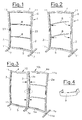
- the wall element of Fig. 1 consists of a frame 1 consisting of two substantially vertically arranged first struts 2, 3 and two substantially horizontally arranged second struts 5, 6 is composed.
- Frame 1 is a string 6 suspended, which is the actual privacy represents.
- Foot elements 7 are used for safe installation of the partition.
- two horizontally arranged stiffening struts 8 are provided, which adjoin support the first struts 2, 3 and are suspended in these.
- Fig. 3 shows a partition composed of two wall elements 10, 10a is.
- a first strut 2 of the first wall element 10 corresponds in its Form thereby a first strut 3a of the second wall element 10a, so that these essentially seamlessly connect to each other.
- the two wall elements 10, 10a are interconnected by at least one bracket 9, which in Fig. 4th is shown in enlarged scale.
- FIG. 3 it can be seen from Fig. 3 that the second struts 4, 5 of the first wall element 10 are curved forward, while the second struts 4a, 5a of the second wall element 10a are curved backwards.
- Forward or after Rear refers to the plane defined by the corner points 11 and 11a of the Frame 1 and 1a of the wall elements 10 and 10a is clamped on which struts 2, 3, 4, 5; 2a, 3a, 4a, 5a are hinged together.
- the first struts 2, 3 of the first wall element 10 are in the through the corners 11th spanned plane curved outwards, so that the first wall element 10th has a convex shape, in contrast, the first struts 2a, 3a of the second wall element 10a curved inwards, so that the second Wall element 10a has a concave shape.
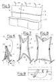
- FIG. 5 shows a variant in which at the first struts 2, 3 Storage elements 12, 13 are removably attached. Furthermore, at the top second struts 4 lighting elements 14 provided in a removable manner.
- FIGS. 6 to 9 show the unfolding of a wall element according to the invention 10.
- the pivot arranged foot elements 7 unfolded.
- the first struts 2, 3 erected according to the arrow 16 placing in the middle of the first struts 2, 3 provided hinge joints 22, 23 brought into their extended position become.
- the second struts 4, 5 unfolded by the Hinge joints 24, 25 of these struts 4, 5 brought into their extended position become.
- the present invention enables a stable and shapely training To achieve a partition that has a high functional value, as they in a simple way is very small collapsible.
Landscapes
- Engineering & Computer Science (AREA)
- Architecture (AREA)
- Physics & Mathematics (AREA)
- Electromagnetism (AREA)
- Civil Engineering (AREA)
- Structural Engineering (AREA)
- Optical Communication System (AREA)
- Iron Core Of Rotating Electric Machines (AREA)
- Mirrors, Picture Frames, Photograph Stands, And Related Fastening Devices (AREA)
- Immobilizing And Processing Of Enzymes And Microorganisms (AREA)
- Devices For Conveying Motion By Means Of Endless Flexible Members (AREA)
- Extensible Doors And Revolving Doors (AREA)
- Rigid Containers With Two Or More Constituent Elements (AREA)
- Packaging Of Annular Or Rod-Shaped Articles, Wearing Apparel, Cassettes, Or The Like (AREA)
- Combined Devices Of Dampers And Springs (AREA)
- Pharmaceuticals Containing Other Organic And Inorganic Compounds (AREA)
- Detergent Compositions (AREA)
- Acyclic And Carbocyclic Compounds In Medicinal Compositions (AREA)
- Fencing (AREA)
Abstract
Description
- Fig. 1
- eine Ausführungsvariante der erfindungsgemäßen Trennwand in einer axonometrischen Darstellung;
- Fig. 2
- eine Darstellung entsprechend Fig. 1 zur Erklärung des Einsetzens von Versteifungsstreben;
- Fig. 3
- eine weitere Ausführungsvariante einer Trennwand bestehend aus zwei Wandelementen;
- Fig. 4
- ein Detail von Fig. 3;
- Fig. 5
- eine weitere Ausführungsvariante der Erfindung in axonometrischer Darstellung;
- Fig. 6,
- Fig. 7 und Fig. 8 Darstellungen zur Erklärung des Entfaltens eines erfindungsgemäßen Wandelements; und
- Fig. 9
- ein Detail von Fig. 8.
Claims (11)
- Mobile Trennwand, bestehend aus mindestens einem Wandelement (10, 10a), mit einem faltbaren, bevorzugt im Wesentlichen rechteckig oder quadratisch ausgebildeten Rahmen (1) und einer in dem Rahmen (1) gehalten flexiblen Bespannung (6), dadurch gekennzeichnet, dass der Rahmen (1) folgende Bauelemente aufweist:zwei in Gebrauchsstellung im Wesentlichen senkrecht angeordnete erste Streben (2, 3; 2a, 3a), die vorzugsweise in ihrem mittleren Bereich jeweils ein Gelenk (22, 23) aufweisen;zwei in Gebrauchsstellung im Wesentlichen waagrecht angeordnete zweite Streben (4, 5; 4a, 5a), die in ihrem mittleren Bereich jeweils ein Gelenk (24, 25) aufweisen und die im Bereich ihrer Enden gelenkig an den Enden der ersten Streben (2, 3; 2a, 3a) befestigt sind;Fußelemente (7) zur sicheren Aufstellung der Trennwand.
- Trennwand nach Anspruch 1, dadurch gekennzeichnet, dass die ersten Streben (2, 3; 2a, 3a) innerhalb der durch die vier Eckpunkte (11) definierten Ebene liegen und gekrümmt ausgebildet sind und/oder dass die zweiten Streben (4, 5; 4a, 5a) gegenüber der durch die vier Eckpunkte (11) definierten Ebene gekrümmt ausgebildet sind.
- Trennwand nach Anspruch 1 oder 2, dadurch gekennzeichnet, dass die Gelenke (22, 23) der ersten Streben (2, 3; 2a, 3a) als Scharniergelenke ausgebildet sind und jeweils eine Gelenksachse aufweisen, die im Wesentlichen parallel zu der durch die vier Eckpunkte (11) definierten Ebene angeordnet ist und vorzugsweise innerhalb dieser Ebene liegt.
- Trennwand nach einem der Ansprüche 1 bis 3, dadurch gekennzeichnet, dass die Gelenke (24, 25) der zweiten Streben (4, 5; 4a, 5a) als Scharniergelenke ausgebildet sind und jeweils eine Gelenksachse aufweisen, die im Wesentlichen senkrecht auf die durch die vier Eckpunkte (11) definierten Ebene angeordnet ist.
- Trennwand nach einem der Ansprüche 1 bis 4, dadurch gekennzeichnet, dass im Bereich der Gelenke (22, 23, 24, 25) Halteklinken (18) vorgesehen sind, um die Gelenke (22, 23, 24, 25) in der Gebrauchsstellung arretieren zu können.
- Trennwand nach einem der Ansprüche 1 bis 7, dadurch gekennzeichnet, dass die Fußelemente (7) einklappbar ausgebildet sind.
- Trennwand nach einem der Ansprüche 1 bis 6, dadurch gekennzeichnet, dass mehrere Wandelemente (10, 10a) vorgesehen sind, die zu einer Trennwand verbindbar sind, wobei die Form einer ersten Strebe (2, 3) eines ersten Wandelements (10) an die Form einer ersten Strebe (2a, 3a) des zweiten Wandelements (10a) angepasst ist.
- Trennwand nach Anspruch 7, dadurch gekennzeichnet, dass die erste Strebe (2, 3) des ersten Wandelements (10) konvex gekrümmt ist und dass die erste Strebe (2a, 3a) des zweiten Wandelements (10a) konkav gekrümmt ist.
- Trennwand nach einem der Ansprüche 1 bis 8, dadurch gekennzeichnet, dass mindestens eine Versteifungsstrebe (8) vorgesehen ist, die zwischen die ersten Streben (2, 3; 2a, 3a) eines Wandelements (10, 10a) einspannbar ist.
- Trennwand nach einem der Ansprüche 1 bis 9, dadurch gekennzeichnet, dass der Rahmen (1) aus Aluminiumprofilen, aus Kunststoffprofilen oder aus Holz hergestellt ist.
- Trennwand nach einem der Ansprüche 1 bis 10, dadurch gekennzeichnet, dass mindestens ein an den ersten Streben (2, 3; 2a, 3a) befestigbares Ablageelement (12, 13) vorgesehen ist.
Priority Applications (1)
| Application Number | Priority Date | Filing Date | Title |
|---|---|---|---|
| SI200430708T SI1529891T1 (sl) | 2003-11-06 | 2004-11-05 | Mobilna ločevalna stena |
Applications Claiming Priority (2)
| Application Number | Priority Date | Filing Date | Title |
|---|---|---|---|
| AT17762003 | 2003-11-06 | ||
| AT0177603A AT413322B (de) | 2003-11-06 | 2003-11-06 | Mobile trennwand |
Publications (3)
| Publication Number | Publication Date |
|---|---|
| EP1529891A2 true EP1529891A2 (de) | 2005-05-11 |
| EP1529891A3 EP1529891A3 (de) | 2006-04-05 |
| EP1529891B1 EP1529891B1 (de) | 2008-02-13 |
Family
ID=34427313
Family Applications (1)
| Application Number | Title | Priority Date | Filing Date |
|---|---|---|---|
| EP04026235A Expired - Lifetime EP1529891B1 (de) | 2003-11-06 | 2004-11-05 | Mobile Trennwand |
Country Status (4)
| Country | Link |
|---|---|
| EP (1) | EP1529891B1 (de) |
| AT (2) | AT413322B (de) |
| DE (1) | DE502004006176D1 (de) |
| SI (1) | SI1529891T1 (de) |
Cited By (1)
| Publication number | Priority date | Publication date | Assignee | Title |
|---|---|---|---|---|
| WO2013076663A2 (en) | 2011-11-24 | 2013-05-30 | Faculdade De Ciências E Tecnologia Da Universidade Nova De Lisboa | Mobile interior space divider module |
Citations (2)
| Publication number | Priority date | Publication date | Assignee | Title |
|---|---|---|---|---|
| DE3921913A1 (de) | 1989-07-04 | 1991-01-17 | Burkhard Nobbe | Faltwand mit verbesserten eckgelenken |
| DE29919367U1 (de) | 1999-11-04 | 2000-02-17 | Schubert, Jürgen, 80333 München | Paravent/Raumteiler, der auch beleuchtet werden kann |
Family Cites Families (4)
| Publication number | Priority date | Publication date | Assignee | Title |
|---|---|---|---|---|
| US4147198A (en) * | 1977-10-03 | 1979-04-03 | Extraversion, Inc. | Portable display system |
| SE446590B (sv) * | 1985-02-15 | 1986-09-29 | T Hennix Reklamatelje Ab | Skermanordning |
| US5131448A (en) * | 1991-07-03 | 1992-07-21 | Channel-Kor Systems Inc. | Panel device |
| DE20302301U1 (de) * | 2003-02-13 | 2003-05-08 | Müller, Melina, 96126 Maroldsweisach | Faltmodul |
-
2003
- 2003-11-06 AT AT0177603A patent/AT413322B/de not_active IP Right Cessation
-
2004
- 2004-11-05 DE DE502004006176T patent/DE502004006176D1/de not_active Expired - Lifetime
- 2004-11-05 SI SI200430708T patent/SI1529891T1/sl unknown
- 2004-11-05 EP EP04026235A patent/EP1529891B1/de not_active Expired - Lifetime
- 2004-11-05 AT AT04026235T patent/ATE386174T1/de not_active IP Right Cessation
Patent Citations (2)
| Publication number | Priority date | Publication date | Assignee | Title |
|---|---|---|---|---|
| DE3921913A1 (de) | 1989-07-04 | 1991-01-17 | Burkhard Nobbe | Faltwand mit verbesserten eckgelenken |
| DE29919367U1 (de) | 1999-11-04 | 2000-02-17 | Schubert, Jürgen, 80333 München | Paravent/Raumteiler, der auch beleuchtet werden kann |
Cited By (1)
| Publication number | Priority date | Publication date | Assignee | Title |
|---|---|---|---|---|
| WO2013076663A2 (en) | 2011-11-24 | 2013-05-30 | Faculdade De Ciências E Tecnologia Da Universidade Nova De Lisboa | Mobile interior space divider module |
Also Published As
| Publication number | Publication date |
|---|---|
| ATA17762003A (de) | 2005-07-15 |
| EP1529891A3 (de) | 2006-04-05 |
| EP1529891B1 (de) | 2008-02-13 |
| ATE386174T1 (de) | 2008-03-15 |
| SI1529891T1 (sl) | 2008-10-31 |
| DE502004006176D1 (de) | 2008-03-27 |
| AT413322B (de) | 2006-02-15 |
Similar Documents
| Publication | Publication Date | Title |
|---|---|---|
| DE69130538T2 (de) | Faltbare dachkonstruktion mit gelenkig verbundenen enden, die mit nichtzusammendrückbaren drehpunkten ausgestattet sind | |
| DE69924616T2 (de) | Aufrichtbarer Unterstand mit Giebeldach | |
| DE69516890T2 (de) | Entfaltbare mobile unterkunftseinheit | |
| DE69200255T2 (de) | Modulartrennwandsystem. | |
| DE60208896T2 (de) | Befestigung für wandelemente | |
| DE60201571T2 (de) | Schwimmbadleiter | |
| DE112017007152T5 (de) | Faltbares Zelt | |
| DE102006001785B4 (de) | Zelt mit einem Vordachteil | |
| DE69719977T2 (de) | Zusammenfaltbares zelt | |
| DE2723149C3 (de) | Klapptisch an einer Armlehne bzw. einer Seitenwange eines Sitzes, insbesondere Schienenfahrzeugsitzes | |
| DE202021002287U1 (de) | Faltbare Rahmenkonstruktion für mobile Theken mit innenliegender Arbeitsfläche, integriertem Fixierungsmechanismus und textiler Hüllkonstruktion | |
| DE202018103732U1 (de) | Verbindungsstruktur für eine Markise | |
| EP1529891B1 (de) | Mobile Trennwand | |
| DE202020006170U1 (de) | Entfaltbares Zelt mit biegebeanspruchten Bögen | |
| DE2328179A1 (de) | Montagefussboden | |
| DE29807750U1 (de) | Schirm | |
| CH651621A5 (en) | Vertically adjustable post and railing with vertically adjustable posts | |
| DE202021100420U1 (de) | Wäschetrocknungsgestell | |
| DE2703168A1 (de) | Falttisch | |
| DE10218906B4 (de) | Überdachung für Sitzgarnituren | |
| DE19901607C2 (de) | Schalldämpfungsmittel | |
| DE20212550U1 (de) | Wohnwagen-Vorzelt | |
| DE202018103802U1 (de) | Verbindungsstruktur von Schrägstange und Säule eines Markisendachteils | |
| DE20010038U1 (de) | Zeltartige Vorrichtung zum Unterstellen, insbesondere Umkleidekabine | |
| DE202008000094U1 (de) | Klappstuhl mit einer bogenförmigen Tragrahmeneinheit |
Legal Events
| Date | Code | Title | Description |
|---|---|---|---|
| PUAI | Public reference made under article 153(3) epc to a published international application that has entered the european phase |
Free format text: ORIGINAL CODE: 0009012 |
|
| AK | Designated contracting states |
Kind code of ref document: A2 Designated state(s): AT BE BG CH CY CZ DE DK EE ES FI FR GB GR HU IE IS IT LI LU MC NL PL PT RO SE SI SK TR |
|
| AX | Request for extension of the european patent |
Extension state: AL HR LT LV MK YU |
|
| PUAL | Search report despatched |
Free format text: ORIGINAL CODE: 0009013 |
|
| AK | Designated contracting states |
Kind code of ref document: A3 Designated state(s): AT BE BG CH CY CZ DE DK EE ES FI FR GB GR HU IE IS IT LI LU MC NL PL PT RO SE SI SK TR |
|
| AX | Request for extension of the european patent |
Extension state: AL HR LT LV MK YU |
|
| 17P | Request for examination filed |
Effective date: 20060926 |
|
| AKX | Designation fees paid |
Designated state(s): AT BE BG CH CY CZ DE DK EE ES FI FR GB GR HU IE IS IT LI LU MC NL PL PT RO SE SI SK TR |
|
| GRAP | Despatch of communication of intention to grant a patent |
Free format text: ORIGINAL CODE: EPIDOSNIGR1 |
|
| GRAS | Grant fee paid |
Free format text: ORIGINAL CODE: EPIDOSNIGR3 |
|
| GRAA | (expected) grant |
Free format text: ORIGINAL CODE: 0009210 |
|
| AK | Designated contracting states |
Kind code of ref document: B1 Designated state(s): AT BE BG CH CY CZ DE DK EE ES FI FR GB GR HU IE IS IT LI LU MC NL PL PT RO SE SI SK TR |
|
| REG | Reference to a national code |
Ref country code: GB Ref legal event code: FG4D Free format text: NOT ENGLISH |
|
| REG | Reference to a national code |
Ref country code: CH Ref legal event code: EP |
|
| REG | Reference to a national code |
Ref country code: IE Ref legal event code: FG4D Free format text: LANGUAGE OF EP DOCUMENT: GERMAN |
|
| REF | Corresponds to: |
Ref document number: 502004006176 Country of ref document: DE Date of ref document: 20080327 Kind code of ref document: P |
|
| PG25 | Lapsed in a contracting state [announced via postgrant information from national office to epo] |
Ref country code: FI Free format text: LAPSE BECAUSE OF FAILURE TO SUBMIT A TRANSLATION OF THE DESCRIPTION OR TO PAY THE FEE WITHIN THE PRESCRIBED TIME-LIMIT Effective date: 20080213 Ref country code: ES Free format text: LAPSE BECAUSE OF FAILURE TO SUBMIT A TRANSLATION OF THE DESCRIPTION OR TO PAY THE FEE WITHIN THE PRESCRIBED TIME-LIMIT Effective date: 20080524 Ref country code: IS Free format text: LAPSE BECAUSE OF FAILURE TO SUBMIT A TRANSLATION OF THE DESCRIPTION OR TO PAY THE FEE WITHIN THE PRESCRIBED TIME-LIMIT Effective date: 20080613 |
|
| REG | Reference to a national code |
Ref country code: CH Ref legal event code: NV Representative=s name: ISLER & PEDRAZZINI AG |
|
| NLV1 | Nl: lapsed or annulled due to failure to fulfill the requirements of art. 29p and 29m of the patents act | ||
| PG25 | Lapsed in a contracting state [announced via postgrant information from national office to epo] |
Ref country code: PL Free format text: LAPSE BECAUSE OF FAILURE TO SUBMIT A TRANSLATION OF THE DESCRIPTION OR TO PAY THE FEE WITHIN THE PRESCRIBED TIME-LIMIT Effective date: 20080213 |
|
| REG | Reference to a national code |
Ref country code: IE Ref legal event code: FD4D |
|
| ET | Fr: translation filed | ||
| PG25 | Lapsed in a contracting state [announced via postgrant information from national office to epo] |
Ref country code: PT Free format text: LAPSE BECAUSE OF FAILURE TO SUBMIT A TRANSLATION OF THE DESCRIPTION OR TO PAY THE FEE WITHIN THE PRESCRIBED TIME-LIMIT Effective date: 20080714 Ref country code: NL Free format text: LAPSE BECAUSE OF FAILURE TO SUBMIT A TRANSLATION OF THE DESCRIPTION OR TO PAY THE FEE WITHIN THE PRESCRIBED TIME-LIMIT Effective date: 20080213 Ref country code: IE Free format text: LAPSE BECAUSE OF FAILURE TO SUBMIT A TRANSLATION OF THE DESCRIPTION OR TO PAY THE FEE WITHIN THE PRESCRIBED TIME-LIMIT Effective date: 20080213 Ref country code: SE Free format text: LAPSE BECAUSE OF FAILURE TO SUBMIT A TRANSLATION OF THE DESCRIPTION OR TO PAY THE FEE WITHIN THE PRESCRIBED TIME-LIMIT Effective date: 20080513 Ref country code: DK Free format text: LAPSE BECAUSE OF FAILURE TO SUBMIT A TRANSLATION OF THE DESCRIPTION OR TO PAY THE FEE WITHIN THE PRESCRIBED TIME-LIMIT Effective date: 20080213 |
|
| PG25 | Lapsed in a contracting state [announced via postgrant information from national office to epo] |
Ref country code: RO Free format text: LAPSE BECAUSE OF FAILURE TO SUBMIT A TRANSLATION OF THE DESCRIPTION OR TO PAY THE FEE WITHIN THE PRESCRIBED TIME-LIMIT Effective date: 20080213 |
|
| PLBE | No opposition filed within time limit |
Free format text: ORIGINAL CODE: 0009261 |
|
| STAA | Information on the status of an ep patent application or granted ep patent |
Free format text: STATUS: NO OPPOSITION FILED WITHIN TIME LIMIT |
|
| 26N | No opposition filed |
Effective date: 20081114 |
|
| PG25 | Lapsed in a contracting state [announced via postgrant information from national office to epo] |
Ref country code: BG Free format text: LAPSE BECAUSE OF FAILURE TO SUBMIT A TRANSLATION OF THE DESCRIPTION OR TO PAY THE FEE WITHIN THE PRESCRIBED TIME-LIMIT Effective date: 20080513 Ref country code: EE Free format text: LAPSE BECAUSE OF FAILURE TO SUBMIT A TRANSLATION OF THE DESCRIPTION OR TO PAY THE FEE WITHIN THE PRESCRIBED TIME-LIMIT Effective date: 20080213 |
|
| PGFP | Annual fee paid to national office [announced via postgrant information from national office to epo] |
Ref country code: SK Payment date: 20090204 Year of fee payment: 5 |
|
| BERE | Be: lapsed |
Owner name: PERTILLER, MATTHAUS Effective date: 20081130 |
|
| PG25 | Lapsed in a contracting state [announced via postgrant information from national office to epo] |
Ref country code: MC Free format text: LAPSE BECAUSE OF NON-PAYMENT OF DUE FEES Effective date: 20081130 |
|
| PG25 | Lapsed in a contracting state [announced via postgrant information from national office to epo] |
Ref country code: CY Free format text: LAPSE BECAUSE OF FAILURE TO SUBMIT A TRANSLATION OF THE DESCRIPTION OR TO PAY THE FEE WITHIN THE PRESCRIBED TIME-LIMIT Effective date: 20080213 |
|
| PG25 | Lapsed in a contracting state [announced via postgrant information from national office to epo] |
Ref country code: BE Free format text: LAPSE BECAUSE OF NON-PAYMENT OF DUE FEES Effective date: 20081130 |
|
| PG25 | Lapsed in a contracting state [announced via postgrant information from national office to epo] |
Ref country code: AT Free format text: LAPSE BECAUSE OF NON-PAYMENT OF DUE FEES Effective date: 20081105 |
|
| PGFP | Annual fee paid to national office [announced via postgrant information from national office to epo] |
Ref country code: SI Payment date: 20091105 Year of fee payment: 6 |
|
| PGFP | Annual fee paid to national office [announced via postgrant information from national office to epo] |
Ref country code: FR Payment date: 20091208 Year of fee payment: 6 Ref country code: GB Payment date: 20091222 Year of fee payment: 6 |
|
| PG25 | Lapsed in a contracting state [announced via postgrant information from national office to epo] |
Ref country code: LU Free format text: LAPSE BECAUSE OF NON-PAYMENT OF DUE FEES Effective date: 20081105 Ref country code: HU Free format text: LAPSE BECAUSE OF FAILURE TO SUBMIT A TRANSLATION OF THE DESCRIPTION OR TO PAY THE FEE WITHIN THE PRESCRIBED TIME-LIMIT Effective date: 20080814 |
|
| REG | Reference to a national code |
Ref country code: SK Ref legal event code: MM4A Ref document number: E 3790 Country of ref document: SK Effective date: 20091105 |
|
| PG25 | Lapsed in a contracting state [announced via postgrant information from national office to epo] |
Ref country code: TR Free format text: LAPSE BECAUSE OF FAILURE TO SUBMIT A TRANSLATION OF THE DESCRIPTION OR TO PAY THE FEE WITHIN THE PRESCRIBED TIME-LIMIT Effective date: 20080213 Ref country code: SK Free format text: LAPSE BECAUSE OF NON-PAYMENT OF DUE FEES Effective date: 20091105 |
|
| PG25 | Lapsed in a contracting state [announced via postgrant information from national office to epo] |
Ref country code: GR Free format text: LAPSE BECAUSE OF FAILURE TO SUBMIT A TRANSLATION OF THE DESCRIPTION OR TO PAY THE FEE WITHIN THE PRESCRIBED TIME-LIMIT Effective date: 20080514 |
|
| PGFP | Annual fee paid to national office [announced via postgrant information from national office to epo] |
Ref country code: CH Payment date: 20101201 Year of fee payment: 7 |
|
| PGFP | Annual fee paid to national office [announced via postgrant information from national office to epo] |
Ref country code: IT Payment date: 20101129 Year of fee payment: 7 |
|
| GBPC | Gb: european patent ceased through non-payment of renewal fee |
Effective date: 20101105 |
|
| REG | Reference to a national code |
Ref country code: FR Ref legal event code: ST Effective date: 20110801 |
|
| REG | Reference to a national code |
Ref country code: SI Ref legal event code: KO00 Effective date: 20110721 |
|
| REG | Reference to a national code |
Ref country code: DE Ref legal event code: R082 Ref document number: 502004006176 Country of ref document: DE Representative=s name: KATSCHER HABERMANN PATENTANWAELTE, DE |
|
| REG | Reference to a national code |
Ref country code: DE Ref legal event code: R082 Ref document number: 502004006176 Country of ref document: DE Representative=s name: PATENTANWAELTE KATSCHER HABERMANN, DE Effective date: 20110907 Ref country code: DE Ref legal event code: R081 Ref document number: 502004006176 Country of ref document: DE Owner name: PERTILLER, MATTHAEUS, AT Free format text: FORMER OWNER: PERTILLER, MATTHAEUS, HOF, AT Effective date: 20110907 |
|
| PG25 | Lapsed in a contracting state [announced via postgrant information from national office to epo] |
Ref country code: FR Free format text: LAPSE BECAUSE OF NON-PAYMENT OF DUE FEES Effective date: 20101130 |
|
| PG25 | Lapsed in a contracting state [announced via postgrant information from national office to epo] |
Ref country code: SI Free format text: LAPSE BECAUSE OF NON-PAYMENT OF DUE FEES Effective date: 20101106 Ref country code: GB Free format text: LAPSE BECAUSE OF NON-PAYMENT OF DUE FEES Effective date: 20101105 |
|
| PGFP | Annual fee paid to national office [announced via postgrant information from national office to epo] |
Ref country code: CZ Payment date: 20111107 Year of fee payment: 8 |
|
| REG | Reference to a national code |
Ref country code: CH Ref legal event code: PL |
|
| PG25 | Lapsed in a contracting state [announced via postgrant information from national office to epo] |
Ref country code: CH Free format text: LAPSE BECAUSE OF NON-PAYMENT OF DUE FEES Effective date: 20111130 Ref country code: LI Free format text: LAPSE BECAUSE OF NON-PAYMENT OF DUE FEES Effective date: 20111130 |
|
| PG25 | Lapsed in a contracting state [announced via postgrant information from national office to epo] |
Ref country code: IT Free format text: LAPSE BECAUSE OF NON-PAYMENT OF DUE FEES Effective date: 20111105 |
|
| PG25 | Lapsed in a contracting state [announced via postgrant information from national office to epo] |
Ref country code: CZ Free format text: LAPSE BECAUSE OF NON-PAYMENT OF DUE FEES Effective date: 20121105 |
|
| PGFP | Annual fee paid to national office [announced via postgrant information from national office to epo] |
Ref country code: DE Payment date: 20180131 Year of fee payment: 14 |
|
| REG | Reference to a national code |
Ref country code: DE Ref legal event code: R119 Ref document number: 502004006176 Country of ref document: DE |
|
| PG25 | Lapsed in a contracting state [announced via postgrant information from national office to epo] |
Ref country code: DE Free format text: LAPSE BECAUSE OF NON-PAYMENT OF DUE FEES Effective date: 20190601 |