EP1529986A1 - Vérin à vis lineaire - Google Patents
Vérin à vis lineaire Download PDFInfo
- Publication number
- EP1529986A1 EP1529986A1 EP04026150A EP04026150A EP1529986A1 EP 1529986 A1 EP1529986 A1 EP 1529986A1 EP 04026150 A EP04026150 A EP 04026150A EP 04026150 A EP04026150 A EP 04026150A EP 1529986 A1 EP1529986 A1 EP 1529986A1
- Authority
- EP
- European Patent Office
- Prior art keywords
- slider
- actuation shaft
- ballscrew
- elastic means
- actuator according
- Prior art date
- Legal status (The legal status is an assumption and is not a legal conclusion. Google has not performed a legal analysis and makes no representation as to the accuracy of the status listed.)
- Withdrawn
Links
- 230000008878 coupling Effects 0.000 claims abstract description 11
- 238000010168 coupling process Methods 0.000 claims abstract description 11
- 238000005859 coupling reaction Methods 0.000 claims abstract description 11
- 238000003466 welding Methods 0.000 claims description 14
- 230000006835 compression Effects 0.000 claims description 4
- 238000007906 compression Methods 0.000 claims description 4
- 230000000295 complement effect Effects 0.000 claims description 3
- 230000003134 recirculating effect Effects 0.000 claims description 2
- 230000000694 effects Effects 0.000 claims 1
- 230000037431 insertion Effects 0.000 claims 1
- 238000003780 insertion Methods 0.000 claims 1
- 230000033001 locomotion Effects 0.000 description 8
- 230000000670 limiting effect Effects 0.000 description 3
- 230000005540 biological transmission Effects 0.000 description 1
- 238000006243 chemical reaction Methods 0.000 description 1
- 230000007717 exclusion Effects 0.000 description 1
- 238000000034 method Methods 0.000 description 1
- 238000012986 modification Methods 0.000 description 1
- 230000004048 modification Effects 0.000 description 1
- 230000008569 process Effects 0.000 description 1
- 230000035945 sensitivity Effects 0.000 description 1
Images


Classifications
-
- B—PERFORMING OPERATIONS; TRANSPORTING
- B23—MACHINE TOOLS; METAL-WORKING NOT OTHERWISE PROVIDED FOR
- B23K—SOLDERING OR UNSOLDERING; WELDING; CLADDING OR PLATING BY SOLDERING OR WELDING; CUTTING BY APPLYING HEAT LOCALLY, e.g. FLAME CUTTING; WORKING BY LASER BEAM
- B23K11/00—Resistance welding; Severing by resistance heating
- B23K11/30—Features relating to electrodes
- B23K11/31—Electrode holders and actuating devices therefor
-
- F—MECHANICAL ENGINEERING; LIGHTING; HEATING; WEAPONS; BLASTING
- F16—ENGINEERING ELEMENTS AND UNITS; GENERAL MEASURES FOR PRODUCING AND MAINTAINING EFFECTIVE FUNCTIONING OF MACHINES OR INSTALLATIONS; THERMAL INSULATION IN GENERAL
- F16H—GEARING
- F16H25/00—Gearings comprising primarily only cams, cam-followers and screw-and-nut mechanisms
- F16H25/18—Gearings comprising primarily only cams, cam-followers and screw-and-nut mechanisms for conveying or interconverting oscillating or reciprocating motions
- F16H25/20—Screw mechanisms
- F16H25/22—Screw mechanisms with balls, rollers, or similar members between the co-operating parts; Elements essential to the use of such members
-
- F—MECHANICAL ENGINEERING; LIGHTING; HEATING; WEAPONS; BLASTING
- F16—ENGINEERING ELEMENTS AND UNITS; GENERAL MEASURES FOR PRODUCING AND MAINTAINING EFFECTIVE FUNCTIONING OF MACHINES OR INSTALLATIONS; THERMAL INSULATION IN GENERAL
- F16H—GEARING
- F16H25/00—Gearings comprising primarily only cams, cam-followers and screw-and-nut mechanisms
- F16H25/18—Gearings comprising primarily only cams, cam-followers and screw-and-nut mechanisms for conveying or interconverting oscillating or reciprocating motions
- F16H25/20—Screw mechanisms
- F16H25/24—Elements essential to such mechanisms, e.g. screws, nuts
- F16H25/2454—Brakes; Rotational locks
Definitions
- the present invention relates to a linear screw actuator.
- linear actuator for example electrically-operated actuators
- actuation shaft a shaft into a translational motion of a slider
- slider which is accordingly actuated so as to perform the most disparate functions.
- Couplings of the screw-and-nut type between the actuation shaft and the slider have been widely used to perform this motion conversion; these couplings allow to position the slider with extreme precision and to apply thereto even very high torques associated with considerable translational speeds both during advancement and during retraction.
- a typical field of application of linear actuators of the types described above is for example, among others, the field of resistance, spot, roller or similar welding machines, which in order to be able to perform welding operations correctly must be able to apply intense pressures to the parts to be joined in short time intervals, performing swift and precise movements of the electrodes.
- the sliders and other parts moved by said actuators may often accidentally encounter, in their stroke, foreign objects or parts to be joined that are incorrectly positioned and cause a sudden impact, which due to the inertia accumulated in the rotor may damage the actuation components.
- the aim of the present invention is to obviate the above-cited drawback, by providing a linear screw actuator that is suitable to operate effectively in any condition, even in situations in which unexpected obstacles or foreign objects may potentially occur during the advancement of the slider, possibly causing an impact with sudden stop.
- an object of the present invention is to provide a linear screw actuator that is extremely versatile in use and is suitable for technological applications of various kinds.
- Another object of the present invention is to provide a linear screw actuator that has a simple structure, is relatively easy to provide in practice, safe in use, effective in operation, and has a relatively low cost.
- linear screw actuator which comprises a rotatable actuation shaft, with which a slider is associated by means of a screw-and-nut coupling, said slider being movable between two mutually opposite end positions, characterized in that it comprises a rotation-preventing limiter that is suitable to cushion elastically the accidental impact of said slider against foreign objects in any position of its advancement stroke along said actuation shaft.
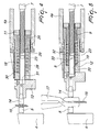
- the reference numeral 1 generally designates a linear screw actuator according to the invention.
- the embodiment of the actuator shown in the figures refers, in the specific case, to an electric resistance-welding machine, generally designated by the reference numeral 2, which has the so-called C-shaped configuration; however, it is noted that the linear actuator according to the invention may be used effectively in any other kind of technical or technological application without any exclusion.
- the welding machine 2 comprises a frame 3, with which a fixed arm 4 and a hollow support 4a are rigidly coupled; the fixed arm 4 is bent substantially at right angles and is provided with a first electrode 5 at its free end.
- the linear actuator of the electrically-operated type, comprises a motor 6 (for example of the so-called brushless type), which is fixed to the frame 3 and is provided with an actuation shaft 7.
- the actuation shaft 7 is threaded externally and is associated with a slider 8 by means of a screw-and-nut coupling with a lead screw 9.
- the screw-and-nut coupling described above allows to convert the rotary motion of the actuation shaft 7 into a translational motion of the slider 8 between two mutually opposite stroke limit end positions, of which one is a retracted position (the slider 8 is proximate to the stator 6) and one is a forward position (the slider is proximate to the free end of the actuation shaft 7).
- the slider 8 is shaped like an elongated parallelepiped with a substantially square transverse cross-section with rounded comers, and is slidingly engaged along a square guide 10, which has a complementary cross-section.
- the square guide 10 is rigidly coupled to the hollow support 4a and is therefore rigidly coupled to the frame 3 of the welding machine 2, so that rotation of the slider 8 with respect to the frame 3 is prevented.
- the slider 8 forms a first end portion 11 and a second end portion 12, which are mutually opposite; an electrode holder 13 for a second electrode 14 is fixed to the second end portion 12.
- the translational motion of the slider 8 from the first end position, with the lead screw 9 retracted and proximate to the motor 6, to the second end portion, with the lead screw 9 in a forward position proximate to the end of the actuation shaft 7, allows to move the electrode holder 13 with the second electrode 14 to the vicinity of the first electrode 5, so that said electrodes clamp onto the parts 15 to be welded with a predefined force, i.e., the correct welding force set by the user.
- the linear actuator comprises a rotation-preventing limiter 16, which is suitable to cushion elastically the impact of the second electrode 14 against any foreign object 17 that may have accidentally blocked the stroke of the slider 8, or against an incorrectly positioned part 15 to be welded; elastic cushioning of the impact allows to avoid the risk of permanent actuator damage caused by the inevitable moment of inertia of the rotor of the motor 6. Said delay, although being nowadays reduced to a minimum with modem motor control and actuation means, may in fact damage irreparably the mechanical elements of the actuator and also the motor 6, in which intense current peaks occur.
- the recirculating ballscrew 9, which is part of the rotation-preventing limiter 16 for cushioning the impact, is engaged along the thread (which has an appropriate profile) of the actuation shaft 7, which in turn is accommodated slidingly in a longitudinal chamber 18 formed within the slider 8; the chamber 18 forms a bottom 19 proximate to the second end portion 11, in which a circular hole 20 is formed.
- the lead screw 9 forms a first end 21, which is coupled with a side-fit coupling to the slider 8 at the first end portion 11 ( Figures 2 and 3), and a second end 22, which is associated with elastic means 23, which are provided within the chamber 18 and abut against the bottom 19.
- the first end 21 of the lead screw 9 has a substantially square transverse cross-section with rounded comers ( Figure 3) and is engaged slidingly within a respective opening 24, which has a cross-section that is complementary thereto and is provided in the first end portion 11 of the slider 8.
- Said side-fit coupling between the lead screw 9 and the slider 8 prevents mutual rotation of said two components, accordingly allowing torque transmission and therefore advancement along the guide 10.
- the lead screw 9 is accommodated so that it can slide with the first end 21 having a square transverse cross-section engaged in the first end portion 11 of the slider 8 and pushed against the end portion 11 by the pre-loading of the elastic means 23; the second end 22 of the lead screw 9 is accommodated in a sleeve 25, which is also coaxial to the actuation shaft 7 and whose outside diameter is slightly smaller than the inside diameter of the chamber 18 ( Figure 3); said sleeve which forms an internal abutment surface 26 for said bush and an external abutment surface 27, which is substantially constituted by a shoulder that is perpendicular to the axis of symmetry of the sleeve 25.
- the sleeve 25 preferably forms a tubular extension 28, within which the actuation shaft 7 can slide, said shaft being locked axially; said extension is in turn engaged so that it can slide within the circular hole 20 of the slider 8, which instead can move axially.
- the elastic means 23 are advantageously constituted by a helical cylindrical spring, which is coaxial to the actuation shaft 7 and has turns that are wound loosely around the tubular extension 28, with a first end 29 that is actuated by the external abutment surface 27 of the sleeve 25 and a second end 30 that abuts against the bottom 19.
- the electrode holder 13 is affected by a substantially cylindrical recess 31, which is provided coaxially to the circular hole 20 and in which the free end of the tubular extension 28 can be inserted; moreover, the free end of the actuation shaft is provided with a stop ring 32 for limiting the stroke of the lead screw 9, which is preferably fixed by means of a screw 33 and prevents said lead screw from accidentally sliding off.
- the operation of the actuator according to the invention is as follows. In the normal operating conditions of the welding machine 2, welding is performed, in a first step, by positioning the parts to be welded 15 between the electrodes 5 and 14 while said electrodes are mutually spaced and therefore the slider 8 is in the retracted stroke limit position ( Figure 1). An actuation signal sent to the motor 6 then produces the rotation of the actuation shaft 7, which induces the translational motion of the slider 8 with a stroke that moves the second electrode 14 onto the parts 15 to be welded ( Figure 4). It should be noted at this point that the spring 23 is advantageously fitted in the chamber 18 with a certain pre-loading, which is greater than the friction that occurs during the movement of the slider 8 along the shaft 7 and greater than the nominal welding force to be applied to the parts 15.
- the first end 21 can in fact slide freely along the opening 24, while the tubular extension 28 enters the recess 31 by a corresponding extent.
- the elastic compression of the spring 23 on the part of the lead screw 9, by means of the sleeve 25, allows to cushion without damage the intense torque transmitted by the motor 6.
Landscapes
- Engineering & Computer Science (AREA)
- Mechanical Engineering (AREA)
- General Engineering & Computer Science (AREA)
- Resistance Welding (AREA)
Applications Claiming Priority (2)
| Application Number | Priority Date | Filing Date | Title |
|---|---|---|---|
| ITBO20030655 ITBO20030655A1 (it) | 2003-11-06 | 2003-11-06 | Attuatore lineare a vite |
| ITBO20030655 | 2003-11-06 |
Publications (1)
| Publication Number | Publication Date |
|---|---|
| EP1529986A1 true EP1529986A1 (fr) | 2005-05-11 |
Family
ID=34430704
Family Applications (1)
| Application Number | Title | Priority Date | Filing Date |
|---|---|---|---|
| EP04026150A Withdrawn EP1529986A1 (fr) | 2003-11-06 | 2004-11-04 | Vérin à vis lineaire |
Country Status (2)
| Country | Link |
|---|---|
| EP (1) | EP1529986A1 (fr) |
| IT (1) | ITBO20030655A1 (fr) |
Cited By (2)
| Publication number | Priority date | Publication date | Assignee | Title |
|---|---|---|---|---|
| CN102806545A (zh) * | 2012-08-14 | 2012-12-05 | 蚌埠朝阳玻璃机械有限公司 | 定位预拉装置 |
| CN102905835A (zh) * | 2010-04-30 | 2013-01-30 | 本田技研工业株式会社 | 焊枪 |
Citations (3)
| Publication number | Priority date | Publication date | Assignee | Title |
|---|---|---|---|---|
| DE1921252A1 (de) * | 1969-04-25 | 1970-11-05 | Rudolf Betzing | Verstellgeraet mit Einrichtungen zur Umwandlung einer Antriebsumlaufbewegung in eine lineare Arbeitsbewegung,insbesondere elektromechanischer Bremsluefter |
| US5916325A (en) * | 1997-04-03 | 1999-06-29 | Dresser Industries, Inc. | Actuator assembly and torque limiting system for same |
| EP1057569A1 (fr) * | 1999-06-04 | 2000-12-06 | Obara Corporation | Unité d'entraínement d'un dispositif de soudage |
-
2003
- 2003-11-06 IT ITBO20030655 patent/ITBO20030655A1/it unknown
-
2004
- 2004-11-04 EP EP04026150A patent/EP1529986A1/fr not_active Withdrawn
Patent Citations (3)
| Publication number | Priority date | Publication date | Assignee | Title |
|---|---|---|---|---|
| DE1921252A1 (de) * | 1969-04-25 | 1970-11-05 | Rudolf Betzing | Verstellgeraet mit Einrichtungen zur Umwandlung einer Antriebsumlaufbewegung in eine lineare Arbeitsbewegung,insbesondere elektromechanischer Bremsluefter |
| US5916325A (en) * | 1997-04-03 | 1999-06-29 | Dresser Industries, Inc. | Actuator assembly and torque limiting system for same |
| EP1057569A1 (fr) * | 1999-06-04 | 2000-12-06 | Obara Corporation | Unité d'entraínement d'un dispositif de soudage |
Cited By (2)
| Publication number | Priority date | Publication date | Assignee | Title |
|---|---|---|---|---|
| CN102905835A (zh) * | 2010-04-30 | 2013-01-30 | 本田技研工业株式会社 | 焊枪 |
| CN102806545A (zh) * | 2012-08-14 | 2012-12-05 | 蚌埠朝阳玻璃机械有限公司 | 定位预拉装置 |
Also Published As
| Publication number | Publication date |
|---|---|
| ITBO20030655A1 (it) | 2005-05-07 |
Similar Documents
| Publication | Publication Date | Title |
|---|---|---|
| EP0726118B1 (fr) | Actuateur électrique | |
| US9821423B2 (en) | Clamping unit, in particular for use in a machining center, or a turning or milling center | |
| KR100405261B1 (ko) | 전동액추에이터 | |
| CN111670087B (zh) | 机床的内置型电力驱动系统及其运转方法 | |
| US20160245380A1 (en) | Pull and / or push rod | |
| EP1529986A1 (fr) | Vérin à vis lineaire | |
| US20060081079A1 (en) | Linear drive with emergency adjustment possibility | |
| JP6673540B2 (ja) | ナット、送りねじ機構およびステアリングホイールの電動位置調節装置 | |
| US20180145558A1 (en) | Direct drive actuator with switched reluctance motor | |
| KR101222669B1 (ko) | 액츄에이터 | |
| CN109234930B (zh) | 一种缝纫机的自动剪线机构及缝纫机 | |
| JP2000002309A (ja) | アクチュエータ | |
| JPWO2018008120A1 (ja) | 出力装置 | |
| CN116488395A (zh) | 一种电动推杆 | |
| JP2009516590A (ja) | 自律補正システムを備えるクランプ又はグリップツール | |
| KR20120111185A (ko) | 리니어 액츄에이터 | |
| KR102566218B1 (ko) | 낚시용 스피닝 릴 | |
| JP2005321029A (ja) | 直動アクチュエータ | |
| CN113829033B (zh) | 扭簧安装机构及其控制方法 | |
| KR101245479B1 (ko) | 왕복구동장치 | |
| US9156106B2 (en) | Welding gun | |
| JP7092291B1 (ja) | プロジェクションナットの供給装置 | |
| KR102835310B1 (ko) | 가스 스프링 장치 | |
| JP6265038B2 (ja) | 締付ソケット及びソケット切り替え方法 | |
| JP2022109519A (ja) | 直動アクチュエータ |
Legal Events
| Date | Code | Title | Description |
|---|---|---|---|
| PUAI | Public reference made under article 153(3) epc to a published international application that has entered the european phase |
Free format text: ORIGINAL CODE: 0009012 |
|
| AK | Designated contracting states |
Kind code of ref document: A1 Designated state(s): AT BE BG CH CY CZ DE DK EE ES FI FR GB GR HU IE IS IT LI LU MC NL PL PT RO SE SI SK TR |
|
| AX | Request for extension of the european patent |
Extension state: AL HR LT LV MK YU |
|
| 17P | Request for examination filed |
Effective date: 20051107 |
|
| AKX | Designation fees paid |
Designated state(s): AT BE BG CH CY CZ DE DK EE ES FI FR GB GR HU IE IS IT LI LU MC NL PL PT RO SE SI SK TR |
|
| STAA | Information on the status of an ep patent application or granted ep patent |
Free format text: STATUS: THE APPLICATION IS DEEMED TO BE WITHDRAWN |
|
| 18D | Application deemed to be withdrawn |
Effective date: 20060905 |