EP1530004B1 - Grundkörper für eine Leuchte - Google Patents
Grundkörper für eine Leuchte Download PDFInfo
- Publication number
- EP1530004B1 EP1530004B1 EP03025502A EP03025502A EP1530004B1 EP 1530004 B1 EP1530004 B1 EP 1530004B1 EP 03025502 A EP03025502 A EP 03025502A EP 03025502 A EP03025502 A EP 03025502A EP 1530004 B1 EP1530004 B1 EP 1530004B1
- Authority
- EP
- European Patent Office
- Prior art keywords
- base section
- wall elements
- recess
- longitudinal axis
- lampshade
- Prior art date
- Legal status (The legal status is an assumption and is not a legal conclusion. Google has not performed a legal analysis and makes no representation as to the accuracy of the status listed.)
- Expired - Lifetime
Links
Images
Classifications
-
- F—MECHANICAL ENGINEERING; LIGHTING; HEATING; WEAPONS; BLASTING
- F21—LIGHTING
- F21V—FUNCTIONAL FEATURES OR DETAILS OF LIGHTING DEVICES OR SYSTEMS THEREOF; STRUCTURAL COMBINATIONS OF LIGHTING DEVICES WITH OTHER ARTICLES, NOT OTHERWISE PROVIDED FOR
- F21V29/00—Protecting lighting devices from thermal damage; Cooling or heating arrangements specially adapted for lighting devices or systems
- F21V29/50—Cooling arrangements
- F21V29/70—Cooling arrangements characterised by passive heat-dissipating elements, e.g. heat-sinks
- F21V29/74—Cooling arrangements characterised by passive heat-dissipating elements, e.g. heat-sinks with fins or blades
- F21V29/77—Cooling arrangements characterised by passive heat-dissipating elements, e.g. heat-sinks with fins or blades with essentially identical diverging planar fins or blades, e.g. with fan-like or star-like cross-section
- F21V29/773—Cooling arrangements characterised by passive heat-dissipating elements, e.g. heat-sinks with fins or blades with essentially identical diverging planar fins or blades, e.g. with fan-like or star-like cross-section the planes containing the fins or blades having the direction of the light emitting axis
-
- F—MECHANICAL ENGINEERING; LIGHTING; HEATING; WEAPONS; BLASTING
- F21—LIGHTING
- F21S—NON-PORTABLE LIGHTING DEVICES; SYSTEMS THEREOF; VEHICLE LIGHTING DEVICES SPECIALLY ADAPTED FOR VEHICLE EXTERIORS
- F21S8/00—Lighting devices intended for fixed installation
- F21S8/04—Lighting devices intended for fixed installation intended only for mounting on a ceiling or the like overhead structures
- F21S8/06—Lighting devices intended for fixed installation intended only for mounting on a ceiling or the like overhead structures by suspension
-
- F—MECHANICAL ENGINEERING; LIGHTING; HEATING; WEAPONS; BLASTING
- F21—LIGHTING
- F21V—FUNCTIONAL FEATURES OR DETAILS OF LIGHTING DEVICES OR SYSTEMS THEREOF; STRUCTURAL COMBINATIONS OF LIGHTING DEVICES WITH OTHER ARTICLES, NOT OTHERWISE PROVIDED FOR
- F21V17/00—Fastening of component parts of lighting devices, e.g. shades, globes, refractors, reflectors, filters, screens, grids or protective cages
- F21V17/10—Fastening of component parts of lighting devices, e.g. shades, globes, refractors, reflectors, filters, screens, grids or protective cages characterised by specific fastening means or way of fastening
- F21V17/12—Fastening of component parts of lighting devices, e.g. shades, globes, refractors, reflectors, filters, screens, grids or protective cages characterised by specific fastening means or way of fastening by screwing
-
- F—MECHANICAL ENGINEERING; LIGHTING; HEATING; WEAPONS; BLASTING
- F21—LIGHTING
- F21V—FUNCTIONAL FEATURES OR DETAILS OF LIGHTING DEVICES OR SYSTEMS THEREOF; STRUCTURAL COMBINATIONS OF LIGHTING DEVICES WITH OTHER ARTICLES, NOT OTHERWISE PROVIDED FOR
- F21V21/00—Supporting, suspending, or attaching arrangements for lighting devices; Hand grips
- F21V21/10—Pendants, arms, or standards; Fixing lighting devices to pendants, arms, or standards
- F21V21/112—Fixing lighting devices to pendants
-
- F—MECHANICAL ENGINEERING; LIGHTING; HEATING; WEAPONS; BLASTING
- F21—LIGHTING
- F21V—FUNCTIONAL FEATURES OR DETAILS OF LIGHTING DEVICES OR SYSTEMS THEREOF; STRUCTURAL COMBINATIONS OF LIGHTING DEVICES WITH OTHER ARTICLES, NOT OTHERWISE PROVIDED FOR
- F21V27/00—Cable-stowing arrangements structurally associated with lighting devices, e.g. reels
Definitions
- the present invention relates to a luminaire, in particular for illuminating goods display surfaces, with a base body which can be fastened to a ceiling, a lampshade and a lamp socket for a lighting means. Furthermore, the invention relates to a base body for such a lamp.
- Suspended lamps of this type are known in different configurations. They have a base body, which often consists of a brass component with a cylindrical basic shape and having an external thread to screw retaining rings for attaching a lampshade or a lamp holder on the body can.
- the body is formed by star or cross-shaped, interconnected in the region of the longitudinal axis of the body wall elements, which limit channels for heat dissipation and / or cable management side.
- the invention is therefore based on the idea not to form the body as a solid brass component, but to produce in lightweight construction of low-wall elements to be produced, which are arranged along a longitudinal axis of the body cross or star shape and interconnected, for example, welded or glued.
- the wall elements can also be made slotted in the region of the longitudinal axis of the main body, so that they can be inserted into each other for pre-positioning and then connected to each other.
- Another advantage of the inventive design of the body with a cross-shaped or star-shaped cross-section is that the channels formed between the wall elements in the body promote a favorable heat dissipation and provide the opportunity to Power supply cable almost parallel to the longitudinal axis of the lamp to lead.
- the wall elements may be formed from sheet metal strips which are interconnected in the region of the longitudinal axis of the base body and may consist of metal, of a metal alloy, of aluminum or of a plastic.
- the weight of the body and the resulting material costs can be significantly reduced and the heat dissipation promoted.
- fastening means such as cable clamps, clips or the like may be provided on the base body for fixing a power supply cable.
- the power supply cable can be easily and quickly positioned and even fixed with the use of cable clamps that it loads on train can be without the power supply cable moves out of its desired position.
- the base body has a recess, via which the base body can be attached to a lamp suspension.
- This recess may be formed, for example in the form of a slot which extends transversely to the longitudinal axis of the base body and in particular may be formed in an axial projection of the base body.
- This configuration of the recess in the form of a slot it is possible to adjust the base body relative to the lamp suspension, wherein the slot expediently has locking recesses into which a suspension bolt of the lamp suspension can intervene.
- a lampshade made of glass to be attached to the body it may be due to inaccuracies in the manufacture of the lampshade or uneven weight distribution in the component itself to a tilt of the lamp in a central arrangement of the lamp suspension on the body.
- the lamp suspension can be moved from one in the body centrally arranged locking hole in an adjacent detent hole, so that weight or circumference differences of the lampshade can be compensated without costly assembly work.
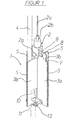
- a base body 1 for a pendant lamp which is used for example for illuminating goods display surfaces and suspended via a lamp suspension 2, which consists of a suspension pin 2a, an adapter 2b and a steel cable 2c, on a ceiling, not shown is.
- the main body 1 is formed in this embodiment of two cross-shaped metal strips 3a, 3b, which are slotted, are stretched and welded together. In this case, channels are formed between the adjacent metal strips 3a, 3b, through which the heat generated at a light bulb, not shown, simply dissipated upward and a power supply cable 4 can be pulled through.
- the metal strips 3a, 3b have at their the outer periphery of the base body 1 forming edges on each other corresponding threaded portions 5, which together form an external thread on the fastener here in the shape of retaining rings 6 can be screwed for attaching other components.
- the sheet metal strip 3a has a recess in the form of an oblong hole 8 extending transversely to the longitudinal axis of the base body 1, which passes through a plurality of adjacent locking holes 9 is formed and is penetrated by the suspension bolt 2a of the lamp suspension 2.
- a recess 10 is provided in the lower region of the sheet metal strip 3c, which is penetrated by a cable clamp 11.
- the cable clamp 11 is attached via two screws 12 to the sheet metal strip 3a and fixes the power supply cable 4 so that it can be loaded on train, without it moved out of its predetermined position.
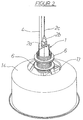
- FIG. 2 shows a perspective view of a luminaire into which the main body 1 according to FIG. 1 is installed.
- main body 1 On the main body 1 four retaining rings 6 are screwed in pairs in this embodiment. Between the lower pair of retaining rings 6, a holder 14 is fixed, which is bow-shaped in this embodiment and holds a lamp holder, not shown, and a diffuser 14 in a predetermined position.
- the upper pair of retaining rings 6 serves to attach a lampshade, not shown, to the luminaire.
Landscapes
- Engineering & Computer Science (AREA)
- General Engineering & Computer Science (AREA)
- Non-Portable Lighting Devices Or Systems Thereof (AREA)
- Vessels And Coating Films For Discharge Lamps (AREA)
- Fastening Of Light Sources Or Lamp Holders (AREA)
- Arrangement Of Elements, Cooling, Sealing, Or The Like Of Lighting Devices (AREA)
- Common Detailed Techniques For Electron Tubes Or Discharge Tubes (AREA)
Description
- Die vorliegende Erfindung betrifft eine Leuchte, insbesondere zum Beleuchten von Warenpräsentationsflächen, mit einem an einer Decke befestigbaren Grundkörper, einem Lampenschirm und einer Lampenfassung für ein Leuchtmittel. Des weiteren betrifft die Erfindung einen Grundkörper für eine solche Leuchte.
- Hängeleuchten dieser Art sind in unterschiedlichen Ausgestaltungen bekannt. Sie besitzen einen Grundkörper, der häufig aus einem Messingbauteil mit einer zylindrischen Grundform besteht und ein Außengewinde aufweist, um Halteringe zur Befestigung eines Lampenschirms oder einer Lampenfassung auf den Grundkörper aufschrauben zu können.
- Das Dokument US 5,690,424 offenbart einen Grundkörper, an dem radiale Stege vorgesehen sind, die derart ausgebildet sind, daß sie den Lampenschirm tragen können. Dadurch wird zwar erreicht, daß der Grundkörper im Durchmesser reduziert werden kann, jedoch bleibt die zylindrische Grundform des Grundkörpers weiterhin bestehen.
- Derartige Ausführungen des Grundkörpers bringen den Nachteil mit sich, daß die Herstellungs- und Materialkosten sehr hoch sind und der Grundkörper ein sehr hohes Eigengewicht aufweist. Ein weiteres Problem besteht darin, daß bei dem bekannten Grundkörper die von dem Leuchtmittel erzeugte Wärme nur sehr schlecht durch den Grundkörper abgeführt werden kann.
- Es ist daher Aufgabe der vorliegenden Erfindung, einen Grundkörper der eingangs genannten Art bereitzustellen, der kostengünstig herstellbar ist, ein geringes Eigengewicht besitzt und die Möglichkeit einer schnellen und effektiven Wärmeabfuhr bietet.
- Diese Aufgabe wird erfindungsgemäß dadurch gelöst, daß der Grundkörper durch stern- oder kreuzförmig angeordnete, im Bereich der Längsachse des Grundkörpers miteinander verbundene Wandungselemente gebildet ist, welche Kanäle zur Wärmeabfuhr und/oder zur Kabelführung seitlich begrenzen.
- Der Erfindung liegt somit die Überlegung zugrunde, den Grundkörper nicht als Massivbauteil aus Messing auszubilden, sondern in Leichtbauweise aus günstig zu fertigenden Wandungselementen herzustellen, die entlang einer Längsachse des Grundkörpers kreuz- oder sternförmig angeordnet und miteinander verbunden, beispielsweise verschweißt oder verklebt sind. Die Wandungselemente können auch im Bereich der Längsachse des Grundkörpers geschlitzt ausgeführt sein, so daß sie zur Vorpositionierung ineinander gesteckt und anschließend miteinander verbunden werden können.
- Ein weiterer Vorteil der erfindungsgemäßen Ausbildung des Grundkörpers mit einem kreuz- oder sternförmigen Querschnitt besteht darin, daß die zwischen den Wandungselementen gebildeten Kanäle im Grundkörper eine günstige Wärmeabfuhr fördern und die Möglichkeit bieten, ein Stromversorgungskabel nahezu parallel zur Längsachse der Leuchte zu führen.
- Gemäß einer vorteilhaften Ausgestaltung können die Wandungselemente aus Blechstreifen gebildet sein, die im Bereich der Längsachse des Grundkörpers miteinander verbunden sind und aus Metall, aus einer Metallegierung, aus Aluminium oder aus einem Kunststoff bestehen können. Je nach Wahl des Werkstoffes können das Gewicht des Grundkörpers und die anfallenden Materialkosten deutlich verringert sowie die Wärmeabfuhr gefördert werden. Außerdem ergibt sich aus der Wahl des Werkstoffes, ob die Wandungselemente geklebt, gelötet oder miteinander verschweißt werden.
- Um Befestigungsmittel wie beispielsweise Halteringe zur Anbringung weiterer Bauelemente, insbesondere eines Lampenschirmes, auf den Grundkörper aufschrauben zu können, sind die den Außenumfang des Grundkörpers bildenden Kanten der Wandungselemente mit zueinander korrespondierenden Gewindeabschnitten versehen, die gemeinsam ein Außengewinde bilden.
- Gemäß einer vorteilhaften Ausgestaltung können an dem Grundkörper Befestigungsmittel wie Kabelklemmen, Clips o. ä. zur Fixierung eines Stromversorgungskabels vorgesehen sein. Dadurch kann das Stromversorgungskabel einfach und schnell positioniert und beim Einsatz von Kabelklemmen sogar derart fixiert werden, daß es auf Zug belastet werden kann, ohne daß sich das Stromversorgungskabel aus seiner gewünschten Position herausbewegt.
- Gemäß einer bevorzugten Ausführungsform der Erfindung ist vorgesehen, daß der Grundkörper eine Aussparung aufweist, über welche der Grundkörper an einer Lampenaufhängung angebracht werden kann. Diese Aussparung kann beispielsweise in Form eines Langlochs ausgebildet sein, welches sich quer zur Längsachse des Grundkörpers erstreckt und insbesondere in einem axialen Vorsprung des Grundkörpers ausgebildet sein kann. Durch diese Ausgestaltung der Aussparung in Form eines Langlochs ist es möglich, den Grundkörper gegenüber der Lampenaufhängung zu verstellen, wobei das Langloch zweckmäßiger Weise Rastausnehmungen aufweist, in die ein Aufhängungsbolzen der Lampenaufhängung eingreifen kann. Wenn nun beispielsweise ein Lampenschirm aus Glas an dem Grundkörper befestigt werden soll, kann es durch Ungenauigkeiten bei der Herstellung des Lampenschirmes oder bei ungleichmäßiger Gewichtsverteilung im Bauteil selbst zu einer Schieflage der Leuchte bei zentraler Anordnung der Lampenaufhängung an dem Grundkörper kommen. Um diese Schrägstellung auszugleichen, kann die Lampenaufhängung von einer in dem Grundkörper zentral angeordneten Rastbohrung in eine benachbarte Rastbohrung verschoben werden, so daß Gewichts- bzw. Umfangsunterschiede des Lampenschirmes ohne aufwendigen Montageaufwand ausgeglichen werden können.
- Hinsichtlich weiterer vorteilhafter Ausgestaltungen der Erfindung wird auf die Unteransprüche sowie die nachfolgende Beschreibung eines Ausführungsbeispiels unter Bezugnahme auf die beiliegende Zeichnung verwiesen. In der Zeichnung zeigt:
- Figur 1
- eine perspektivische Darstellung eines erfindungsgemäßen Grundkörpers und
- Figur 2
- eine erfindungsgemäße Leuchte mit dem Grundkörper gemäß Figur 1.
- Die Figur 1 zeigt eine perspektivische Darstellung eines Grundkörpers 1 für eine Hängeleuchte, die beispielsweise zum Beleuchten von Warenpräsentationsflächen eingesetzt wird und über eine Lampenaufhängung 2, welche sich aus einem Aufhängungsbolzen 2a, einem Adapterstück 2b und einem Stahlseil 2c besteht, an einer nicht dargestellten Decke aufgehängt ist. Der Grundkörper 1 ist in diesem Ausführungsbeispiel aus zwei kreuzförmig angeordneten Blechstreifen 3a, 3b gebildet, die geschlitzt ausgebildet, ineinandergestreckt und untereinander verschweißt sind. Dabei werden zwischen den benachbarten Blechstreifen 3a, 3b Kanäle gebildet, durch welche die an einem nicht dargestellten Leuchtmittel entstehende Wärme einfach nach oben hin abgeführt und ein Stromversorgungskabel 4 durchgezogen werden kann.
- Die Blechstreifen 3a, 3b weisen an ihren den Außenumfang des Grundkörpers 1 bildenden Kanten miteinander korrespondierende Gewindeabschnitte 5 auf, die gemeinsam ein Außengewinde bilden, auf das Befestigungsmittel hier in der Form von Halteringen 6 zur Anbringung weiterer Bauelemente aufschraubbar sind.
- Der eine Blechstreifen 3a steht an seinem oberen Ende über den zweiten Blechstreifen 3b vor und bildet so einen axialen Vorsprung 7. Im Bereich dieses Vorsprungs 7 weist der Blechstreifen 3a eine Aussparung in Form eines quer zur Längsachse des Grundkörpers 1 verlaufenden Langloches 8 auf, welches durch mehrere nebeneinander liegende Rastbohrungen 9 gebildet ist und von dem Aufhängungsbolzen 2a der Lampenaufhängung 2 durchgriffen wird.
- Wird ein nicht dargestellter Lampenschirm aus Glas an dem Grundkörper 1 angebracht, kann es durch Ungleichmäßigkeiten bezüglich der Gewichtsverteilung in dem Glas oder durch geometrische Ungleichmäßigkeiten in der Gestaltung des Lampenschirms zu einer Schieflage der Leuchte kommen. Diese kann dann durch ein Querverschieben der Lampenaufhängung 2 in der Aussparung 8 zu einer weiteren Rastbohrung 9 ausgeglichen werden, so daß die Leuchte wieder gerade hängt.
- Im unteren Bereich des Blechstreifens 3c ist eine Aussparung 10 vorgesehen, welche von einer Kabelklemme 11 durchgriffen wird. Die Kabelklemme 11 ist über zwei Schrauben 12 an dem Blechstreifen 3a befestigt und fixiert das Stromversorgungskabel 4, so daß dieses auf Zug belastbar ist, ohne daß es sich dabei aus seiner vorgegebenen Position herausbewegt.
- Die Figur 2 zeigt eine perspektivische Darstellung einer Leuchte, in die der Grundkörper 1 gemäß Figur 1 eingebaut ist. Auf den Grundkörper 1 sind in diesem Ausführungsbeispiel vier Halteringe 6 paarweise aufgeschraubt. Zwischen dem unteren Paar von Halteringen 6 ist ein Halter 14 befestigt, welcher in diesem Ausführungsbeispiel bügelförmig ausgebildet ist und eine nicht dargestellte Lampenfassung sowie einen Diffusor 14 in einer vorgegebenen Position hält. Das obere Paar von Halteringen 6 dient dazu, einen nicht dargestellten Lampenschirm an der Leuchte zu befestigen.
Claims (13)
- Grundkörper (1) für eine Leuchte zur Anbringung einer Lampenfassung und eines Lampenschirmes, dadurch gekennzeichnet, daß der Grundkörper (1) durch kreuz- oder sternförmig angeordnete, im Bereich der Längsachse des Grundkörpers (1) miteinander verbundene Wandungselemente (3a, 3b) gebildet ist, welche Kanäle zur Wärmeabfuhr und/oder zur Kabelführung seitlich begrenzen.
- Grundkörper (1) nach Anspruch 1, dadurch gekennzeichnet, daß die Wandungselemente (3a, 3b) aus im Bereich der Längsachse des Grundkörpers (1) miteinander verbundenen Blechstreifen gebildet sind.
- Grundkörper (1) nach Anspruch 1 oder 2, dadurch gekennzeichnet, daß die Wandungselemente (3a, 3b) aus Metall, aus einer Metallegierung, aus Aluminium oder aus einem Kunststoff bestehen.
- Grundkörper (1) nach einem der Ansprüche 1 bis 3, dadurch gekennzeichnet, daß die Wandungselemente (3a, 3b) geklebt oder miteinander verschweißt sind.
- Grundkörper (1) nach einem der Ansprüche 2 bis 4, dadurch gekennzeichnet, daß die Wandungselemente (3a, 3b) an ihren den Außenumfang des Grundkörpers (1) bildenden Kanten miteinander korrespondierende Gewindeabschnitte (5) aufweisen, die gemeinsam ein Außengewinde bilden, auf das Befestigungsmittel (6) zur Anbringung weiterer Bauelemente, insbesondere des Lampenschirmes, aufschraubbar sind.
- Grundkörper (1) nach Anspruch 5, dadurch gekennzeichnet, daß die Befestigungsmittel (6) als Halteringe ausgebildet sind.
- Grundkörper (1) nach einem der vorhergehenden Ansprüche, dadurch gekennzeichnet, daß an dem Grundkörper (1) Befestigungsmittel (11) zur Fixierung eines Stromversorgungskabels (4) vorgesehen sind.
- Grundkörper (1) nach Anspruch 7, dadurch gekennzeichnet, daß die Befestigungsmittel (11) als Kabelklemmen oder als Clips ausgebildet sind.
- Grundkörper (1) nach einem der vorherigen Ansprüche,
dadurch gekennzeichnet, daß der Grundkörper (1) mindestens eine Aussparung (8) aufweist, mit welcher der Grundkörper (1) an einer Lampenaufhängung (2) anbringbar ist. - Grundkörper (1) nach Anspruch 9, dadurch gekennzeichnet, daß die Aussparung (8) in einem axialen Vorsprung (7) des Grundkörpers (1) ausgebildet ist.
- Grundkörper (1) nach Anspruch 9 oder 10, dadurch gekennzeichnet, daß die Aussparung (8) in Form eines quer zur Längsachse des Grundkörpers verlaufendes Langlochs ausgebildet ist.
- Grundkörper (1) nach Anspruch 11, dadurch gekennzeichnet, daß die Aussparung (8) Rastbohrungen (9) für den Eingriff eines Aufhängungsbolzens (2a) der Lampenaufhängung (2) aufweist.
- Leuchte, insbesondere zum Beleuchten von Warenpräsentationsflächen, mit einem an Decke befestigbaren Grundkörper (1), einem Lampenschirm und einer Lampenfassung für ein Leuchtmittel, dadurch gekennzeichnet, daß der Grundkörper (1) nach einem der vorhergehenden Ansprüche ausgebildet ist.
Priority Applications (4)
| Application Number | Priority Date | Filing Date | Title |
|---|---|---|---|
| ES03025502T ES2257630T3 (es) | 2003-11-06 | 2003-11-06 | Cuerpo de base para una lampara. |
| DE50302374T DE50302374D1 (de) | 2003-11-06 | 2003-11-06 | Grundkörper für eine Leuchte |
| AT03025502T ATE317523T1 (de) | 2003-11-06 | 2003-11-06 | Grundkörper für eine leuchte |
| EP03025502A EP1530004B1 (de) | 2003-11-06 | 2003-11-06 | Grundkörper für eine Leuchte |
Applications Claiming Priority (1)
| Application Number | Priority Date | Filing Date | Title |
|---|---|---|---|
| EP03025502A EP1530004B1 (de) | 2003-11-06 | 2003-11-06 | Grundkörper für eine Leuchte |
Publications (2)
| Publication Number | Publication Date |
|---|---|
| EP1530004A1 EP1530004A1 (de) | 2005-05-11 |
| EP1530004B1 true EP1530004B1 (de) | 2006-02-08 |
Family
ID=34429282
Family Applications (1)
| Application Number | Title | Priority Date | Filing Date |
|---|---|---|---|
| EP03025502A Expired - Lifetime EP1530004B1 (de) | 2003-11-06 | 2003-11-06 | Grundkörper für eine Leuchte |
Country Status (4)
| Country | Link |
|---|---|
| EP (1) | EP1530004B1 (de) |
| AT (1) | ATE317523T1 (de) |
| DE (1) | DE50302374D1 (de) |
| ES (1) | ES2257630T3 (de) |
Families Citing this family (1)
| Publication number | Priority date | Publication date | Assignee | Title |
|---|---|---|---|---|
| EP2118560B1 (de) * | 2007-02-05 | 2013-05-01 | Louis Poulsen Lighting A/s | Anbringungseinrichtung |
Family Cites Families (2)
| Publication number | Priority date | Publication date | Assignee | Title |
|---|---|---|---|---|
| US5690424A (en) * | 1995-05-08 | 1997-11-25 | Justice Design Group, Inc. | Mounting apparatus for lighting fixtures |
| AUPR598201A0 (en) * | 2001-06-28 | 2001-07-19 | Showers International Pty Ltd | Light assembly for solid state light devices |
-
2003
- 2003-11-06 AT AT03025502T patent/ATE317523T1/de not_active IP Right Cessation
- 2003-11-06 EP EP03025502A patent/EP1530004B1/de not_active Expired - Lifetime
- 2003-11-06 DE DE50302374T patent/DE50302374D1/de not_active Expired - Fee Related
- 2003-11-06 ES ES03025502T patent/ES2257630T3/es not_active Expired - Lifetime
Also Published As
| Publication number | Publication date |
|---|---|
| EP1530004A1 (de) | 2005-05-11 |
| DE50302374D1 (de) | 2006-04-20 |
| ES2257630T3 (es) | 2006-08-01 |
| ATE317523T1 (de) | 2006-02-15 |
Similar Documents
| Publication | Publication Date | Title |
|---|---|---|
| EP2093476B1 (de) | Leuchtenprofil | |
| DE3615488C2 (de) | ||
| DE202015100867U1 (de) | Leuchtenanordnung | |
| EP0795719B1 (de) | Modular aufgebaute Leuchteneinheit | |
| EP1530004A1 (de) | Grundkörper für eine Leuchte | |
| DE3214596A1 (de) | Aufhaengevorrichtung fuer leuchten | |
| EP2757309A2 (de) | Leuchtdiodenmodul und Leuchte mit mindestens einem Leuchtdiodenmodul | |
| EP0658720A1 (de) | Leuchteneinheit | |
| WO2020035118A1 (de) | Leuchte für arbeite-, film- oder sportveranstaltungen | |
| EP2085684A1 (de) | Leuchte mit selbsttragender Reflektoreinheit | |
| DE102006020224A1 (de) | Reflektorvorrichtung für eine Beleuchtungsvorrichtung | |
| DE29602567U1 (de) | Lichtpaneel | |
| AT14937U1 (de) | Seilabhängungsvorrichtung | |
| DE9307685U1 (de) | Deckenleuchte | |
| EP2674663B1 (de) | Beleuchtungsvorrichtung | |
| DE202024105218U1 (de) | Lineare Beleuchtungsvorrichtung für Möbelelemente | |
| DE102021109939A1 (de) | Modul für eine Leuchte, insbesondere für eine Lichtbandleuchte | |
| DE102016208401B4 (de) | Strahler | |
| DE202023102977U1 (de) | Stehleuchte mit einstellbarem Leuchtenkopf mit Anschlag | |
| DE29907199U1 (de) | Langfeldleuchte | |
| DE102024130840A1 (de) | Trägermodul, Trägervorrichtung, Trägersystem und Verfahren zur Herstellung eines Trägermoduls | |
| DE102013102166A1 (de) | Außenbeleuchtungsvorrichtung | |
| DE8700709U1 (de) | Tragvorrichtung für bühnentechnische Gerätschaften | |
| DE19740870A1 (de) | Stativklemme | |
| DE2315488B1 (de) | Leuchte |
Legal Events
| Date | Code | Title | Description |
|---|---|---|---|
| PUAI | Public reference made under article 153(3) epc to a published international application that has entered the european phase |
Free format text: ORIGINAL CODE: 0009012 |
|
| 17P | Request for examination filed |
Effective date: 20040514 |
|
| AK | Designated contracting states |
Kind code of ref document: A1 Designated state(s): AT BE BG CH CY CZ DE DK EE ES FI FR GB GR HU IE IT LI LU MC NL PT RO SE SI SK TR |
|
| AX | Request for extension of the european patent |
Extension state: AL LT LV MK |
|
| GRAP | Despatch of communication of intention to grant a patent |
Free format text: ORIGINAL CODE: EPIDOSNIGR1 |
|
| GRAS | Grant fee paid |
Free format text: ORIGINAL CODE: EPIDOSNIGR3 |
|
| GRAA | (expected) grant |
Free format text: ORIGINAL CODE: 0009210 |
|
| AKX | Designation fees paid |
Designated state(s): AT BE BG CH CY CZ DE DK EE ES FI FR GB GR HU IE IT LI LU MC NL PT RO SE SI SK TR |
|
| AK | Designated contracting states |
Kind code of ref document: B1 Designated state(s): AT BE BG CH CY CZ DE DK EE ES FI FR GB GR HU IE IT LI LU MC NL PT RO SE SI SK TR |
|
| PG25 | Lapsed in a contracting state [announced via postgrant information from national office to epo] |
Ref country code: IT Free format text: LAPSE BECAUSE OF FAILURE TO SUBMIT A TRANSLATION OF THE DESCRIPTION OR TO PAY THE FEE WITHIN THE PRESCRIBED TIME-LIMIT;WARNING: LAPSES OF ITALIAN PATENTS WITH EFFECTIVE DATE BEFORE 2007 MAY HAVE OCCURRED AT ANY TIME BEFORE 2007. THE CORRECT EFFECTIVE DATE MAY BE DIFFERENT FROM THE ONE RECORDED. Effective date: 20060208 Ref country code: SK Free format text: LAPSE BECAUSE OF FAILURE TO SUBMIT A TRANSLATION OF THE DESCRIPTION OR TO PAY THE FEE WITHIN THE PRESCRIBED TIME-LIMIT Effective date: 20060208 Ref country code: SI Free format text: LAPSE BECAUSE OF FAILURE TO SUBMIT A TRANSLATION OF THE DESCRIPTION OR TO PAY THE FEE WITHIN THE PRESCRIBED TIME-LIMIT Effective date: 20060208 |
|
| REG | Reference to a national code |
Ref country code: GB Ref legal event code: FG4D Free format text: NOT ENGLISH |
|
| REG | Reference to a national code |
Ref country code: CH Ref legal event code: EP |
|
| GBT | Gb: translation of ep patent filed (gb section 77(6)(a)/1977) |
Effective date: 20060208 |
|
| REG | Reference to a national code |
Ref country code: IE Ref legal event code: FG4D Free format text: LANGUAGE OF EP DOCUMENT: GERMAN |
|
| REG | Reference to a national code |
Ref country code: RO Ref legal event code: EPE |
|
| REF | Corresponds to: |
Ref document number: 50302374 Country of ref document: DE Date of ref document: 20060420 Kind code of ref document: P |
|
| PG25 | Lapsed in a contracting state [announced via postgrant information from national office to epo] |
Ref country code: DK Free format text: LAPSE BECAUSE OF FAILURE TO SUBMIT A TRANSLATION OF THE DESCRIPTION OR TO PAY THE FEE WITHIN THE PRESCRIBED TIME-LIMIT Effective date: 20060508 Ref country code: SE Free format text: LAPSE BECAUSE OF FAILURE TO SUBMIT A TRANSLATION OF THE DESCRIPTION OR TO PAY THE FEE WITHIN THE PRESCRIBED TIME-LIMIT Effective date: 20060508 Ref country code: BG Free format text: LAPSE BECAUSE OF FAILURE TO SUBMIT A TRANSLATION OF THE DESCRIPTION OR TO PAY THE FEE WITHIN THE PRESCRIBED TIME-LIMIT Effective date: 20060508 |
|
| PG25 | Lapsed in a contracting state [announced via postgrant information from national office to epo] |
Ref country code: PT Free format text: LAPSE BECAUSE OF FAILURE TO SUBMIT A TRANSLATION OF THE DESCRIPTION OR TO PAY THE FEE WITHIN THE PRESCRIBED TIME-LIMIT Effective date: 20060710 |
|
| ET | Fr: translation filed | ||
| REG | Reference to a national code |
Ref country code: ES Ref legal event code: FG2A Ref document number: 2257630 Country of ref document: ES Kind code of ref document: T3 |
|
| PGFP | Annual fee paid to national office [announced via postgrant information from national office to epo] |
Ref country code: DE Payment date: 20060918 Year of fee payment: 4 |
|
| PGFP | Annual fee paid to national office [announced via postgrant information from national office to epo] |
Ref country code: CZ Payment date: 20061020 Year of fee payment: 4 |
|
| PGFP | Annual fee paid to national office [announced via postgrant information from national office to epo] |
Ref country code: RO Payment date: 20061024 Year of fee payment: 4 |
|
| PGFP | Annual fee paid to national office [announced via postgrant information from national office to epo] |
Ref country code: FR Payment date: 20061117 Year of fee payment: 4 |
|
| PGFP | Annual fee paid to national office [announced via postgrant information from national office to epo] |
Ref country code: FI Payment date: 20061121 Year of fee payment: 4 Ref country code: IE Payment date: 20061121 Year of fee payment: 4 |
|
| PGFP | Annual fee paid to national office [announced via postgrant information from national office to epo] |
Ref country code: AT Payment date: 20061122 Year of fee payment: 4 Ref country code: BE Payment date: 20061122 Year of fee payment: 4 |
|
| PGFP | Annual fee paid to national office [announced via postgrant information from national office to epo] |
Ref country code: ES Payment date: 20061123 Year of fee payment: 4 |
|
| PG25 | Lapsed in a contracting state [announced via postgrant information from national office to epo] |
Ref country code: MC Free format text: LAPSE BECAUSE OF NON-PAYMENT OF DUE FEES Effective date: 20061130 |
|
| PGFP | Annual fee paid to national office [announced via postgrant information from national office to epo] |
Ref country code: IT Payment date: 20061130 Year of fee payment: 4 |
|
| PLBE | No opposition filed within time limit |
Free format text: ORIGINAL CODE: 0009261 |
|
| STAA | Information on the status of an ep patent application or granted ep patent |
Free format text: STATUS: NO OPPOSITION FILED WITHIN TIME LIMIT |
|
| 26N | No opposition filed |
Effective date: 20061109 |
|
| PG25 | Lapsed in a contracting state [announced via postgrant information from national office to epo] |
Ref country code: GR Free format text: LAPSE BECAUSE OF FAILURE TO SUBMIT A TRANSLATION OF THE DESCRIPTION OR TO PAY THE FEE WITHIN THE PRESCRIBED TIME-LIMIT Effective date: 20060509 |
|
| BERE | Be: lapsed |
Owner name: *BARO G.M.B.H. & CO. K.G. Effective date: 20071130 |
|
| PG25 | Lapsed in a contracting state [announced via postgrant information from national office to epo] |
Ref country code: EE Free format text: LAPSE BECAUSE OF FAILURE TO SUBMIT A TRANSLATION OF THE DESCRIPTION OR TO PAY THE FEE WITHIN THE PRESCRIBED TIME-LIMIT Effective date: 20060208 |
|
| GBPC | Gb: european patent ceased through non-payment of renewal fee |
Effective date: 20071106 |
|
| PG25 | Lapsed in a contracting state [announced via postgrant information from national office to epo] |
Ref country code: CH Free format text: LAPSE BECAUSE OF NON-PAYMENT OF DUE FEES Effective date: 20071130 Ref country code: HU Free format text: LAPSE BECAUSE OF FAILURE TO SUBMIT A TRANSLATION OF THE DESCRIPTION OR TO PAY THE FEE WITHIN THE PRESCRIBED TIME-LIMIT Effective date: 20060809 Ref country code: FI Free format text: LAPSE BECAUSE OF NON-PAYMENT OF DUE FEES Effective date: 20071106 Ref country code: LU Free format text: LAPSE BECAUSE OF NON-PAYMENT OF DUE FEES Effective date: 20061106 Ref country code: CZ Free format text: LAPSE BECAUSE OF NON-PAYMENT OF DUE FEES Effective date: 20071106 Ref country code: TR Free format text: LAPSE BECAUSE OF FAILURE TO SUBMIT A TRANSLATION OF THE DESCRIPTION OR TO PAY THE FEE WITHIN THE PRESCRIBED TIME-LIMIT Effective date: 20060208 Ref country code: LI Free format text: LAPSE BECAUSE OF NON-PAYMENT OF DUE FEES Effective date: 20071130 |
|
| REG | Reference to a national code |
Ref country code: CH Ref legal event code: PL |
|
| NLV4 | Nl: lapsed or anulled due to non-payment of the annual fee |
Effective date: 20080601 |
|
| PG25 | Lapsed in a contracting state [announced via postgrant information from national office to epo] |
Ref country code: AT Free format text: LAPSE BECAUSE OF NON-PAYMENT OF DUE FEES Effective date: 20071106 |
|
| PG25 | Lapsed in a contracting state [announced via postgrant information from national office to epo] |
Ref country code: BE Free format text: LAPSE BECAUSE OF NON-PAYMENT OF DUE FEES Effective date: 20071130 |
|
| PG25 | Lapsed in a contracting state [announced via postgrant information from national office to epo] |
Ref country code: NL Free format text: LAPSE BECAUSE OF NON-PAYMENT OF DUE FEES Effective date: 20080601 Ref country code: DE Free format text: LAPSE BECAUSE OF NON-PAYMENT OF DUE FEES Effective date: 20080603 Ref country code: IE Free format text: LAPSE BECAUSE OF NON-PAYMENT OF DUE FEES Effective date: 20071106 |
|
| REG | Reference to a national code |
Ref country code: FR Ref legal event code: ST Effective date: 20080930 |
|
| PG25 | Lapsed in a contracting state [announced via postgrant information from national office to epo] |
Ref country code: RO Free format text: LAPSE BECAUSE OF NON-PAYMENT OF DUE FEES Effective date: 20071106 Ref country code: CY Free format text: LAPSE BECAUSE OF FAILURE TO SUBMIT A TRANSLATION OF THE DESCRIPTION OR TO PAY THE FEE WITHIN THE PRESCRIBED TIME-LIMIT Effective date: 20060208 |
|
| PG25 | Lapsed in a contracting state [announced via postgrant information from national office to epo] |
Ref country code: GB Free format text: LAPSE BECAUSE OF NON-PAYMENT OF DUE FEES Effective date: 20071106 |
|
| REG | Reference to a national code |
Ref country code: ES Ref legal event code: FD2A Effective date: 20071107 |
|
| PG25 | Lapsed in a contracting state [announced via postgrant information from national office to epo] |
Ref country code: ES Free format text: LAPSE BECAUSE OF NON-PAYMENT OF DUE FEES Effective date: 20071107 Ref country code: FR Free format text: LAPSE BECAUSE OF NON-PAYMENT OF DUE FEES Effective date: 20071130 |
|
| PG25 | Lapsed in a contracting state [announced via postgrant information from national office to epo] |
Ref country code: IT Free format text: LAPSE BECAUSE OF NON-PAYMENT OF DUE FEES Effective date: 20071106 |