EP1530175A2 - Machine de jeu - Google Patents
Machine de jeu Download PDFInfo
- Publication number
- EP1530175A2 EP1530175A2 EP04026702A EP04026702A EP1530175A2 EP 1530175 A2 EP1530175 A2 EP 1530175A2 EP 04026702 A EP04026702 A EP 04026702A EP 04026702 A EP04026702 A EP 04026702A EP 1530175 A2 EP1530175 A2 EP 1530175A2
- Authority
- EP
- European Patent Office
- Prior art keywords
- medal
- medals
- gaming machine
- opening
- accumulating parts
- Prior art date
- Legal status (The legal status is an assumption and is not a legal conclusion. Google has not performed a legal analysis and makes no representation as to the accuracy of the status listed.)
- Granted
Links
Images





Classifications
-
- G—PHYSICS
- G07—CHECKING-DEVICES
- G07F—COIN-FREED OR LIKE APPARATUS
- G07F17/00—Coin-freed apparatus for hiring articles; Coin-freed facilities or services
- G07F17/32—Coin-freed apparatus for hiring articles; Coin-freed facilities or services for games, toys, sports, or amusements
- G07F17/3286—Type of games
- G07F17/3297—Fairground games, e.g. Tivoli, coin pusher machines, cranes
-
- G—PHYSICS
- G07—CHECKING-DEVICES
- G07F—COIN-FREED OR LIKE APPARATUS
- G07F17/00—Coin-freed apparatus for hiring articles; Coin-freed facilities or services
- G07F17/32—Coin-freed apparatus for hiring articles; Coin-freed facilities or services for games, toys, sports, or amusements
- G07F17/3286—Type of games
- G07F17/3295—Games involving skill, e.g. dexterity, memory, thinking
Definitions
- the present invention relates to a gaming machine that is installed in a so-called game arcade or the like.
- Gaming machines which are equipped with staircase form medal accumulating parts comprising a plurality of step parts, and which are constructed so that medals are paid out from a step part (among the abovementioned plurality of step parts) in accordance with the results of a drawing that is performed when it is acknowledged that a medal has entered a medal receiving opening, have been known in the past (for example, see Japanese Unexamined Patent Publication No. 2001-310077).
- the paying out of medals from the medal accumulating parts can be diversified so that medals are paid out from the step part at the lower end and given to the player, so that medals that are paid out from the step parts on the upper side are accumulated in the step parts on the lower side, or so that medals are paid out from all of the step parts and large quantities of medals are given to the player, in accordance with the drawing results.
- the game contents are such that medals are simply inserted into a fixed medal receiving opening, then whichever player plays the game, the frequency of inserting medals into the medal receiving opening will be generally the same. Therefore, the game results depend on the result of a drawing for determining whether or not a jackpot has been activated, and it is difficult to reflect the skill of the player in the game results.
- an object of the present invention is to provide a gaming machine which creates a rich sense of movement, and which allows the skill of a player to be reflected in the game results, thereby allowing the player to play the game without experiencing boredom.
- the present invention is constructed as follows.
- the gaming machine of the present invention is a gaming machine comprising: a gaming machine having a projection device for projection of medals into a gaming space; the gaming machine having a medal receiving opening for receiving medals that are projected by the projection device; wherein the gaming machine has a medal discharge opening for discharging medals to the outside of the gaming space; wherein the gaming machine has a plurality of medal accumulating parts, and is constructed so that the plurality of medal accumulating parts are sequentially disposed and ranged along the medal discharge opening, characterized the medals that are paid out from the respective medal accumulating parts are sequentially moved and accumulated in the medal accumulating parts that are adjacent on the side of the medal discharge opening, and wherein the medals that are paid out from the medal accumulating part that is located closely to the medal discharge opening are discharged from the medal discharge opening and given to the player; detecting means for detecting the medals that have entered into the medal receiving opening; drawing means for performing a drawing in order to determine the presence or absence of a jackpot when the medals are
- the moving means is a moving unit in which the medal receiving opening is disposed in a suspended fashion, the moving unit causing the medal receiving opening to move upwards and downwards.
- the moving unit comprises: a frame body fixed to a ceiling part inside the gaming space; a raising and lowering motor provided inside the frame body; and a rope winding part attached to the shaft of the raising and lowering motor; the other end of the rope that is wound about the rope winding part being attached to a member coupled to the medal receiving opening.
- an openable and closable lid body is provided in the opening section of the medal receiving opening into which the medals enter, in such a manner that an opening and closing operation of the lid body is performed with a prescribed timing.
- the drawing means performs a drawing in order to determine a presence or absence of a jackpot with respect to the paying out of medals from two or more medal accumulating parts of the plurality of medal accumulating parts, when the medals have been detected by the detecting means.
- the gaming machine may comprise a notification means for making a notification of the drawing results of the drawing means.
- the notification means comprises an LED lamp.
- the notification means comprises an LED pattern display device.
- the respective medal accumulating parts are disposed above the medal accumulating parts that are adjacent on the side of the medal discharge opening, and medals in the respective medal accumulating parts are caused to move by their own weight from these respective medal accumulating parts, and are accumulated in the medal accumulating parts that are adjacent on the side of the medal discharge opening.
- the medals used in the gaming machine in accordance with the present invention may also include other medium, such as a coin or a token, as well.
- Fig. 1 is a perspective view schematically showing one example of a gaming machine of this embodiment.
- the gaming machine 10 comprises a housing 12 which has substantially the shape of a hexagonal column.
- the interior of the game space 13 can be viewed via window parts 14 consisting of a transparent material that constitute parts of the housing 12.
- the ceiling body 11 that forms a part of the housing 12 also consists of a transparent material, so that the interior of the game space 13 can be viewed from above.
- Six game fields 15 constituting targets at which medals are launched from a medal launching device 16 (described later) are respectively disposed inside the game space 13 so that the hexagonal shape is divided into six parts from the center. Furthermore, in the figures, only two of the six game fields 15 are shown.
- the rails 45 are disposed so that these rails are inclined downward from the upper parts of the transporting devices 50 toward a medal accommodating part 90 disposed in the central part of the game space 13.
- the medals that are transported upward by the transporting devices 50 slide down the rails 45 and are accommodated in the medal accommodating part 90.
- the rails 45 consist of a transparent material such as an acrylic resin or the like, and are arranged so that the medals that slide down the rails 45 can be seen from the outside.
- the medals accommodated in the medal accommodating part 90 are supplied to one of a number of medal carrying locations 27 (not shown in the figures) that are respectively provided for the six game fields 15.
- a drawing hereafter referred to as the "supply drawing” that is used to select the medal carrying location 27 that is the object of medal supply among the six medal carrying locations 27 is conducted, and medals are supplied to the medal carrying locations 27 in accordance with the results of this supply drawing.
- Launching devices 16 that are used to launch medals are respectively disposed corresponding to the six game fields 15 in the lower part of the housing 12, so that a maximum of six players can simultaneously play the game. These launching devices 16 are installed so that the devices can pivot in the vertical (up-down) direction and left-right direction within a specified range. The players determine the launching direction of the medals by pivoting the launching devices 16 within the specified range in the vertical and left-right directions, and launch medals by pressing a launch button 122 (not shown in the figures), so that the medals are launched inside the game space 13.
- the permissible pivoting range and the like of the launching devices 16 are set so that the launching devices 16 can project medals only onto the corresponding game fields 15.
- a medal removal opening 31 is disposed beneath each launching device 16, and medals that are discharged to the outside of the game space 13 via the medal discharge opening 17 (not shown in the figures) described later are supplied to the medal removal openings 31, and given to the players.
- medal receiving openings 22 that are used to receive medals that are launched by the launching devices 16 into the game space 13 and projected into the game space 13 are disposed in a suspended fashion in a moving unit 100 for moving the medal receiving openings 22 upwards and downwards.
- This moving unit 100 functions as moving means which move the medal receiving openings 22.
- Two medal receiving openings 22 are provided respectively for each game field 15.
- the moving unit 100 is attached to the ceiling body 11.
- a drawing is performed in order to determine the presence or absence of a jackpot with respect to the paying out of medals from one or more of four medal accumulating parts 20 (20a - 20d), which are described hereafter, and if a jackpot is activated, then medals are paid out from a medal accumulating part 20 determined in accordance with the result of the drawing.
- the moving unit 100 is described in detail hereafter with respect to the drawings.
- Fig. 2 is a perspective view which schematically shows one of the game fields 15 disposed inside the game space 13 of the gaming machine 10 shown in Fig. 1. Furthermore, in the following description, one of the six game fields 15 provided in the gaming machine 10 will be described.
- This game field 15 comprises a medal carrying location 27 and four medal accumulating parts 20 (20a through 20d).
- the medal accumulating parts 20 (20a through 20d) are constructed from the inclined surface of the medal carrying location 27, opening-and-closing doors 21 (21a through 21d) that will be described later, medal receiving openings 22 (22a through 22d) that will be described later, and side plates (not shown in the figures). The side plates are disposed on both side parts of the inclined surface of the medal carrying location 27 so as to contact the medal receiving openings 22.
- Each of the medal accumulating parts 20a through 20d can accumulate medals that are projected by the corresponding launching device 16. Furthermore, the medal accumulating part 20a can accumulate medals that are supplied from the medal accommodating part 90 (see Fig. 1).
- the four medal accumulating parts 20a through 20d are sequentially disposed and ranged along the inclined surface of the medal carrying location 27 toward the player who is playing the game in front.
- Opening-and-closing doors 21a through 21d consisting of a transparent material such as an acrylic resin or the like are respectively disposed before the respective medal accumulating parts 20a through 20d.
- the players playing the game in front of the medal accumulating parts 20a through 20d can visually observe the medals that have accumulated in the medal accumulating parts 20a through 20d via these opening-and-closing doors 21a through 21d.
- the opening-and-closing doors 21 are respectively connected to a stepping motor 32 (not shown in the figures) via a transmission member or the like (not shown in the figures) that can convert the rotational motion of the stepping motor 32 into a rectilinear reciprocating motion, so that the opening-and-closing doors can be moved upward or downward and placed in an open state or closed state by the operation of the stepping motor 32.
- the stepping motor 32 When the stepping motor 32 operates so that the opening-and-closing doors 21a through 21d are placed in an open state, the medals that are blocked slide and move downward along the inclined surface of the medal carrying location 27 as a result of their own weight.
- LED lamps 23a through 23d that can emit light of a plurality of different colors are respectively disposed on the left and right sides of each of the opening-and-closing doors 21a through 21d. If the entry of a medal into a medal receiving opening 22 is acknowledged, a drawing to determine the presence or absence of a jackpot is carried out, and if it is ascertained that a jackpot has been activated, then the LED lamps 23 on the left and right sides are lit with the same color, thus providing notification that a jackpot has been activated.
- the opening-and-closing doors 21a are driven by the stepping motor 32 so that the opening-and-closing doors 21a are placed in an open state.
- the medals that were blocked by the opening-and-closing doors 21a slide downward along the inclined surface of the medal carrying location 27, and are accumulated in the medal accumulating part 21b located beneath the medal accumulating part 20a.
- the entry of a medal into the medal receiving opening 22 is acknowledged, a drawing for determining the presence or absence of a jackpot is carried out, and if a jackpot is activated with respect to the paying out of medals from the medal accumulating part 20a and the medal accumulating part 20b of the four medal accumulating parts 20, then all of the LED lamps 23 blink while changing color, whereupon they are lit with a specified color.
- the two LED lamps 23a relating to the medal accumulating part 20a and the two LED lamps 23b relating to the medal accumulating part 20b are lit respectively with the same color.
- the opening-and-closing doors 21a and the opening-and-closing doors 21b are placed in an open state.
- the medals that are paid out from the medal accumulating parts 20a through 20c respectively move under their own weight into the medal accumulating parts 20b through 20d that are adjacent on the side of the medal discharge opening 17, and that are positioned lower than the medal accumulating parts 20a through 20c, and are accumulated in these medal accumulating parts 20b through 20d.
- the medals that are paid out from the medal accumulating part 20d that is located closely to the medal discharge opening 17 slide downward, and are either carried on the field plate 34 (described later), or caused to drop into the medal discharge opening 17 from the field plate 34 and given to the player, or caused to drop into the medal dropping opening 37 (described later) and conveyed by the abovementioned transporting device 50.
- a horizontal medal push-out part 33 is disposed on the front part of the medal carrying location 27, and a field plate 34 is disposed on the central part of the undersurface of the medal push-out part 33.
- the field plate 34 is connected to a motor 35 (not shown in the figures) via a transmission member (not shown in the figures) or the like that can convert the rotational motion of the motor 35 into a rectilinear reciprocating motion, and the field plate 34 is thus constructed so that this field plate can be caused to perform a reciprocating motion between the front side and inside side by the operation of the motor 35.
- the field plate 34 has a length which is such that medals can be placed on the front side of the medal push-out member 33 even when the field plate 34 has moved to the furthest inside point.
- medal dropping openings 37 are disposed on the left and right sides of the medal discharge opening 17. Projected medals, medals paid out from the medal accumulating part 20d and the like slide down along the inclined surface of the medal carrying location 27 and drop into the medal dropping openings 37, whereupon these medals are transported by the transporting devices 50 and accommodated in the medal accommodating part 90.
- the gaming machine 10 of this embodiment need not necessarily be a so-called pusher gaming machine comprising a medal push-out part 33 and field plate 34; for example, the machine may also be constructed so that the medals that slide downward along the medal carrying location 27 can drop directly into the medal discharge opening 17 or medal dropping openings 37.
- Fig. 3 is a vertical sectional view schematically showing a moving unit 100.
- the moving unit 100 comprises a frame body 101 fixed to the ceiling body 11, a raising and lowering motor 102 provided inside the frame body 101, and a winding part 103 installed on a shaft of the raising and lowering motor 102.
- One end of a rope 104 is wound about the winding part 103 and the other end of the rope 104 is fixed to a coupling bar 106 coupled to the medal receiving opening 22.
- the moving unit 100 is composed so that raising and lowering of the medal receiving opening 22 is performed in a repeated fashion by switching the raising and lowering motor 102 between forward rotation and reverse rotation, at a prescribed timing.
- the timing at which the rotation of the raising and lowering motor 102 is switched may be constant at all times, or it may be changed in specified conditions. Moreover, the rotational speed of the raising and lowering motor 102 may be constant at all times, or it may be changed in specified conditions.
- the medal receiving opening 22 comprises a medal sensor 28, which is an infrared sensor, provided inside the opening.
- a medal that has entered the medal receiving opening 22 is detected by the medal sensor 28 and then continues to fall downwards as indicated by the arrow with the double-dotted line in the drawing.
- the medal sensor 28 functions as detecting means which detect a medal that has entered into the medal receiving opening 22.
- the medal sensor 28 is not limited to being an infrared sensor, but may also be a magnetic proximity type sensor or a mechanical sensor, or the like.
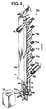
- Fig. 4 is a partially cut-away perspective view which schematically shows this transporting device 50.
- the transporting device 50 is a device in which medals that have dropped into the medal dropping opening 37 (see Fig. 2), been caused to slide down the rails 51 communicating with the medal dropping opening 37, and placed on a stopper 52 on the tip end of the rails 51, are conveyed upward and fed onto rails 45 that communicate with the medal accommodating part 90 (see Fig. 2).
- the stopper 52 on the tip ends of the rails 51 has a comb-form shape, and is constructed with the tip end being bent so that medals that slide downward along the rails 51 can be stopped in the vicinity of the stopper 52.
- the transporting device 50 comprises a medal elevator mechanism 70 that can lift medals that have been placed on the stopper 52.
- the medal elevator mechanism 70 has a plurality of buckets 71 that are used to accommodate the medals carried on the stopper 52, and a bucket driving device 72 containing a motor that is used to circulate the buckets 71 in the vertical direction.
- a sprocket 73 is attached to the drive shat 72a of the motor inside the bucket driving device 72, and a chain 75 to which the plurality of buckets 71 are attached is mounted on this sprocket 73 and another sprocket 73 that is positioned above this sprocket 73.
- the upper sprocket 73 is attached to supporting plates 64a and 64b so that this sprocket 73 is free to rotate.
- a medal supporting plate 71a that is used to support medals is disposed on each bucket 71, and the respective medal supporting plates 71a are inclined downward toward the side of the supporting plate 64a from the side of the supporting plate 64b. Furthermore, the end part on the upper side of each medal supporting plate 71a has a comb-form shape, and when the medal supporting plate 71a is raised from the lower end, the comb part of the medal supporting plate 71a and the comb part of the stopper 52 cross so as to face each other, so that the medals carried on the stopper 52 are scooped up when the medal supporting plate 71a passes the upper side of the stopper 52.
- a medal stopper 76 that is used to prevent the medals from dropping downward from the medal supporting plate 71a of each bucket 71 is disposed on the supporting plate 64a.
- the medal stopper 76 extends in the vertical direction, and when the medal supporting plate 71a carrying the medals reaches the upper end of the medal stopper 76, the medals carried on the medal supporting plate 71a slide downward, and move onto the rails 45.
- a medal hopper that is used to perform the paying out of medals may be disposed inside the housing 12, and the system may be devised so that medals paid out from this medal hopper are supplied to the stopper 52 besides the medals that are supplied to the stopper 52 from the medal dropping openings 37.
- the system may be devised so that medals paid out from this medal hopper are supplied to the stopper 52 besides the medals that are supplied to the stopper 52 from the medal dropping openings 37.
- the system may also be devised so that medals that have dropped from the medal dropping openings 37 are not supplied directly to the medal stopper 52, but are instead temporarily accumulated in the medal hopper, so that medals paid out from the medal hopper are supplied to the stopper 52.
- each transporting device 50 is constructed so that the transported medals can be visually observed from the outside; furthermore, as is described above, the rails 45 that are connected to the transporting device 50 consist of a transparent material. As a result, the player can visually observe the meals that are conveyed to the medal accommodating part 90 by the transporting device 50 and rails 45 via the window part 14 (see Fig. 1).
- Fig. 5A is a plan view which schematically shows the medal accommodating part 90 shown in Fig. 1, and Fig. 5B is a sectional view along line A-A in Fig. 5A.
- the medal accommodating part 90 has a substantially hexagonal spindle shape; furthermore, as is shown in Fig. 5A, six opening-and-closing parts 91 are formed in the circumferential edge part of the medal accommodating part 90 so that these opening-and-closing parts can open and close.
- the opening-and-closing parts 91 When the opening-and-closing parts 91 are in a closed state, the medals that are carried on the inclined surface 98 are blocked by the opening-and-closing parts 91. Then, when the opening-and-closing parts 91 are lowered so that the opening-and-closing parts 91 are placed in an open state, the medals carried on the inclined surface 98 slide downward, and move into the medal accumulating parts 20 (20a through 20d).
- a supply drawing that is used to select the medal carrying location 27 that is the object of medal supply among the six medal carrying locations 27 of the medal accommodating part 90 is performed each time that a specified period of time (e. g., 5 minutes) elapses.
- the opening-and-closing part 91 for the selected medal carrying location 27 is placed in an open state in accordance with the results of this supply drawing, and the medals accommodated in the medal accommodating part 90 are supplied to the medal accumulating part 20a disposed on the medal carrying location 27.
- a tooth-form part 95 is disposed on the lower part of each opening-and-closing part 91. Furthermore, a gear 93 attached to the shat of an opening-and-closing motor 92 (not shown in the figures) is disposed in the vicinity of the lower end of the tooth-form part 95. The gear 93 engages with a gear 94 that is disposed between the tooth-form part 95 of the opening-and-closing part 91 and the gear 93, and the gear 94 engages with the tooth-form part 95.
- a raising limit position sensor 96 which is a mechanical type sensor is disposed in the vicinity of the upper end of the tooth-form part 95
- a lowering limit position sensor which is a mechanical type sensor is disposed on the upper side of the gear 94 in the vicinity of the tooth-form part 95.
- the opening-and-closing motor 92 When the opening-and-closing part 91 is to be opened, the opening-and-closing motor 92 operates so that the gear 93 rotates in the right-hand direction, thus causing the opening-and-closing part 91 to be lowered. Then, when a contact 95a disposed on the upper end of the tooth-form part 95 is detected by the lowering limit position sensor 97 during the lowering of the opening-and-closing part 91, the rotation of the opening-and-closing motor 92 is stopped. Then, when a fixed period of time (e.
- the opening-and-closing motor 92 is caused to rotate in the reverse direction (left-hand rotation), so that the opening-and-closing part 91 is raised.
- the contact 95a is detected by the raising limit position sensor 96 during the raising of the opening-and-closing part 91, the rotation of the opening-and-closing motor 92 is stopped.
- the supply of medals to the medal accumulating part 20a from the medal accommodating part 90 is accomplished by the raising and lowering of the abovementioned opening-and-closing part 91.
- Fig. 5B only the tooth-form part 95 disposed on one side (the upper side in Fig. 5A) of the opening-and-closing part 91 is shown; however, the opening-and-closing part 91 has tooth-form parts 95 on both the left and right sides, and is constructed so that the both the left and right tooth-form parts 95 can be driven by the motor 92. Furthermore, the raising limit position sensor 96 and lowering limit position sensor 97 may be disposed on both the left and right sides, or may be disposed on only one side.
- the raising limit position sensor 96 and lowering limit position sensor 97 are disposed on one side of the opening-and-closing part 91, the detection of the contact 95a by the raising limit position sensor 96 and lowering limit position sensor 97 is acknowledged, and the rotation of motors 92 respectively provided for both the left and right tooth-form parts 95 is stopped.
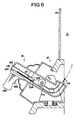
- Fig. 6 is a sectional view which shows the area in the vicinity of one of the launching devices 16 of the housing 12 schematically. Furthermore, in Fig. 6, for convenience of description, a state is shown in which a portion of this launching device 16 is viewed in a sectional view.
- launching device 16 is attached on the lower side of the window part 14 of the housing 12 so that this launching device 16 can pivot within a specified range in the vertical direction and left-right direction.
- the player can cause the launching device 16 to pivot in the vertical direction and left-right direction by operating a lever 120 that is disposed on the launching device 16.
- a launch button 122 is disposed on this lever 120, and the player can launch medals 1 by pressing this launch button 122.
- a medal loading opening 118 is formed in the left side of the launching device 16, and a medal launching opening 119 is formed in the right side of the launching device 16. Furthermore, guide rails 123 that communicate with the medal loading opening 118 and medal launching opening 119 are disposed inside the launching device 16. These guide rails 123 are disposed so that the rails are inclined downward toward the inside end, and are bent upward at an intermediate point. Furthermore, a stopper 121 is disposed inside the launching device 16, and a shutter 124 is disposed to the inside of the stopper 121.
- the stopper 121 can be moved upward and downward by the operation of a solenoid that is attached to the stopper 121, and the shutter 124 can be opened and closed by the operation of a motor that is attached to the shutter 124. Furthermore, the stopper 121 and shutter 124 are disposed at a spacing that is greater than the diameter of the medals 1.
- a launching roller 125 is attached to a launching motor (not shown in the figures) on the right side of the shutter 124.
- the launching roller 125 can be caused to rotate in the direction indicated by the arrow in the figure by the operation of the launching motor.
- the launching roller 125 is disposed so that this roller contacts the medals 1 that slide downward along the guide rails 123.
- the medals 1 can be accelerated, so that the medals 1 can be launched in a good attitude from the medal launching opening 119.
- the stopper 121 When a plurality of medals 1 enter the medal loading opening 118, the plurality of medals 1 are blocked by the shutter 124.
- the stopper 121 is in an open state, and one medal 1 is present between the stopper 121 and the shutter 124.
- the launch button 122 When the launch button 122 is pressed, the stopper 121 moves downward, so that the medal 1 that is present in front of the stopper is blocked; then, immediately afterward, the shutter 124 is placed in a pivoted open state, and the launching roller 125 rotates, so that the medal 1 that is present between the stopper 121 and shutter 124 slides downward along the guide rails 123, is accelerated by contact with the launching roller 125, and is launched from the medal launching opening 119.
- the shutter 124 pivots and is placed in a closed state; furthermore, the stopper 121 moves upward so that a medal 1 is fed out as far as the shutter 124. Then, when the launch button 122 is pressed again, this medal 1 is launched by the method described above.
- the abovementioned elapsed time can be set in accordance with the period of time extending from the point in time at which the shutter 124 is placed in an open state (when the launching device 16 approaches most closely to a horizontal attitude) to the point in time at which the medal 1 passes the lower end of the shutter 124 or the like.
- Fig. 7 is a block diagram showing a schematic view of the internal composition of a gaming machine of this embodiment.
- a control part 60 is provided inside the frame body 12 of the gaming machine 10.
- the control part 60 comprises a central processing unit (CPU) 66, a ROM 62 and a RAM 64.
- the ROM 62 stores game programs that control the flow of the overall games of the gaming machine 10, programs relating to the drawing that is conducted in order to establish the presence or absence of a jackpot, programs used to conduct the supply drawing that is used to select the medal carrying location 27 that is the object of medal supply, audio data that is required in order to generate background music, sound effects, and the like in accordance with the game conditions, and other data. Furthermore, the ROM 62 also stores drawing probability tables that are required in order to conduct the drawing that is used to determine the presence or absence of a jackpot, supply drawing probability tables that are required in order to conduct the supply drawing used to select the medal carrying location 27 that is the object of medal supply among the six medal carrying locations 27, and the like.
- the CPU 66 is connected to the medal sensors 28 and the LED lamps 23 (23a through 23d) via an interface circuit 61.
- a detection signal is sent to the CPU 66 via the interface circuit 61.
- a control signal is sent to the two LED lamps 23 relating to the medal accumulating part to which it is determined to pay out medals on the basis of the drawing result, and this control signal causes the two LED lamps 23 to be lit with the same color.
- the CPU 66 is connected to the medal accommodating part 90 via an interface circuit 63. Each time that a specified period of time has elapsed, the CPU 66 sends a driving signal to the opening-and-closing motor 92, and causes the opening-and-closing motor 92 to operate.
- the CPU 66 receives a detection signal from the lowering limit position sensor 97 during the lowering of the opening-and-closing part 91 by the rotation of the opening-and-closing motor 92, the CPU 66 sends a control signal to the opening-and-closing motor 92 and stops the opening-and-closing motor 92.
- the CPU 66 again sends a control signal to the opening-and-closing motor 92 and causes the opening-and-closing motor 92 to rotate in the reverse direction so that the opening-and-closing part 91 is raised. Furthermore, when the CPU 66 receives a detection signal from the raising limit position sensor 96 during the raising of the opening-and-closing part 91, the CPU 66 sends a control signal to the opening-and-closing motor 92 and stops the opening-and-closing motor 92.
- the CPU 66 is connected to a stepping motor 32, motor 35, raising and lowering motor 102, and speaker 46 via an interface circuit 65.
- the stepping motor 32 is used to open and close the opening-and-closing doors 21 (21a through 21d) of the medal accumulating parts 20 (20a through 20d), and the motor 35 is used to cause a reciprocating motion of the abovementioned field plate.
- the raising and lowering motor 102 is used to move the medal receiving opening upwards and downwards in the vertical direction.
- the speaker 46 is used to output background music, voice, sound effects, or the like, in accordance with the game conditions.
- Fig. 8 is a flow chart which shows the game execution processing routine that is executed in the gaming machine 10 shown in Fig. 1. This subroutine is called up and executed when the power supply of the gaming machine 10 is switched on.
- the CPU 66 determines whether or not a medal has entered either of the two medal receiving openings 22 (step S10). More specifically, the CPU 66 determines whether or not a detection signal has been received from the medal sensor 28 provided in the medal receiving opening 22 detecting a medal that has entered one of the two medal receiving openings 22. In cases where it is determined in step S10 that no medal has entered either of the two medal receiving openings, this subroutine is ended.
- step S12 the CPU 66 next executes drawing processing (step S12).
- the CPU 66 performs a drawing on the basis of the abovementioned drawing probability table in order to determine the presence or absence of a jackpot.
- the results of this drawing are stored in the RAM 64 as drawing data.
- a drawing is performed that determines whether a jackpot has been activated or missed with respect to paying out of medals from one or more of the four medal accumulating parts 20 (medal accumulating parts 20a through 20d).
- the control part 60 functions as drawing means.
- Fig. 9 shows one example of the drawing probability table described above.
- the probability of a jackpot being activated with respect to the paying out of medals from one or more of the four medal accumulating parts is 1/32.
- the table used in the drawing for establishing the presence or absence of a jackpot activation is not limited to the example shown in Fig. 9.
- the type of medal accumulating part to which medals are to be paid out is established in accordance with a random drawing value drawn within a range of 0 to 16383.
- the random drawing value is in the range of 15872 to 15935, then medals are paid out from the medal accumulating part 20a, among the four medal accumulating parts 20.
- the random drawing value is in the range of 16128 to 16159, then medals are paid out from the two medal accumulating parts 20a and 20b among the four medal accumulating parts.
- step S14 the CPU 66 next executes processing that causes the LED lamps 23 to blink.
- step S14 all of the LED lamps 23 (23a through 23d) blink while sequentially changing color. Furthermore, the blinking of these LED lamps 23 is performed for a fixed period of time (e. g., 3 seconds).
- step S14 the CPU 66 next executes processing for causing all of the LED lamps 23 (23a through 23d) to light on the basis of the drawing data stored in the RAM 64 as a result of executing the processing in step S12 (step S16).
- step S18 the CPU 66 next determines whether or not the lit colors of the left and right-hand LED lamps 23 are the same. In this step S18, the CPU 66 determines whether or not the lit colors of the left and right-hand LED lamps 23 are the same, for all of the four medal accumulating parts 20.
- step S18 If it is determined in step S18 that the lit colors of the left and right-hand LED lamps 23 are different in the case of all of the medal accumulating parts 20, then this subroutine is ended.
- step S18 if it is determined in step S18 that the lit colors of the left and right-hand LED lamps 23 are the same in the case of any of the four medal accumulating parts 20, then the CPU 66 next executes processing for opening the opening-and-closing doors of the medal accumulating part 20 at which the lit colors of the left and right-hand LED lamps 23 are the same (step S20).
- step S20 the CPU 66 sends a driving signal to the stepping motor 32 and causes the opening-and-closing doors 21 to be lowered and placed in an open state.
- control part 60 and the stepping motor 32 function as pay-out means.
- step S20 When the processing in step S20 has been executed, this subroutine is ended.
- the entry of a medal into either of the two medal receiving openings 22 is acknowledged, a drawing for the purpose of determining the presence or absence of a jackpot is performed, and if the drawing results indicate that a jackpot has been activated, then the activating of the jackpot is notified to the player by means of the two LED lamps 23 lighting up with the same color, and medals are paid out from the medal accumulating part 20.
- the drawing result indicates that a jackpot has not been activated (in other words, that it has been missed)
- the two LED lamps 23 light up with different colors, thereby notifying the player that the drawing result indicates a miss.
- Fig. 10 is a flow chart which shows the medal supply processing routine that is executed in the gaming machine 10 shown in Fig. 1. This subroutine is called up and executed when the power supply of the gaming machine 10 is switched on.
- the CPU 66 determines whether or not a specified period of time (5 minutes) has elapsed (step S40). In cases where it is determined that this specified period of time has not elapsed, the CPU 66 again performs the determination processing of step S40. On the other hand, in cases where it is determined in step S40 that the abovementioned specified period of time has elapsed, the CPU 66 next executes supply drawing processing (step S42). In this step S42, the CPU 66 performs a drawing on the basis of the supply drawing probability table that is stored in the ROM 62, and selects the medal carrying location 27 that is the object of medal supply among the six medal carrying locations 27 on the basis of the drawing results.
- step S42 When the processing of step S42 has been executed, the CPU 66 next sends a driving signal to the opening-and-closing motor 92 in order to open the opening-and-closing part 91 associated with the medal carrying location 27, that has been selected in step S42, and causes this opening-and-closing motor 92 to rotate (step S44).
- step S44 When the processing of this step S44 is executed, the opening-and-closing motor 92 rotates in the rightward direction, so that the opening-and-closing part 91 is lowered (see Fig. 5).
- step S46 the CPU 66 next determines whether or not a detection signal has been received from the lowering limit position sensor 97 (step S46). Specifically, the CPU 66 determines whether or not a detection signal transmitted from the lowering limit position sensor 97 as a result of the contact 95a disposed on the comb-form part 95 being detected by the lowering limit position sensor 97 during the lowering of the opening-and-closing part 91 has been received.
- step S46 In cases where it is determined in step S46 that a detection signal has not been received, the CPU 66 again performs the determination processing of step S46.
- step S46 the CPU 66 next sends a stopping signal to the opening-and-closing motor 92 in order to stop the lowering of the opening-and-closing part 91, and thus stops the rotation of the opening-and-closing motor 92 (step S48).
- step S48 the CPU 66 next waits until a specified period of time (5 seconds) has elapsed, and maintains the stopped state of the opening-and-closing part 91 (step S50). Then, in order to raise the opening-and-closing part 91, the CPU 66 sends a driving signal to the opening-and-closing motor 92, and causes the opening-and-closing motor 92 to perform reverse rotation (step S52). When the processing of this step S52 is executed, the opening-and-closing motor 92 rotates in the leftward direction, so that the opening-and-closing part 91 is raised (see Fig. 5).
- step S52 the CPU 66 next determines whether or not a detection signal has been received from the raising limit position sensor 96 (step S54). Specifically, the CPU 66 determines whether or not a detection signal transmitted from the raising limit position sensor 96 as a result of the contact 95a disposed on the comb-form part 95 being detected by the raising limit position sensor 96 during the raising of the opening-and-closing part 91 has been received.
- step S54 In cases where it is determined in step S54 that a detection signal has not been received, the CPU 66 again performs the determination processing of step S54.
- step S54 In cases where it is determined in step S54 that a detection signal has been received, the CPU 66 next sends a stopping signal to the opening-and-closing motor 92 in order to stop the raising of the opening-and-closing part 91, and thus stops the rotation of the opening-and-closing motor 92 (step S56).
- step S56 When the processing of step S56 has been executed, this subroutine is ended.
- a supply drawing that is used to select the medal carrying location 27 that is the object of medal supply is performed, and the opening-and-closing part 91 is placed in an open state for a fixed period of time (5 seconds) in order to supply medals to the medal carrying location 27 that is selected on the basis of the drawing results.
- the opening-and-closing part 91 is placed in an open state, the medals slide downward along the inclined surface 98 of the medal accommodating part 90, so that the medals move into the medal accumulating part 20 installed on the medal carrying location 27.
- the gaming machine 10 relating to the embodiment of the present invention, since the medal receiving openings 22 can be moved upwards and downwards by means of the moving unit 100, the game is played while sequentially changing the speed, direction, and the like, at which the medals enter into the moving medal receiving openings 22. Consequently, it is possible to achieve game contents having a rich sense of movement. Moreover, in order to increase the frequency at which the medals enter into the medal receiving openings 22, it is necessary to adjust the speed, direction, and the like, at which the medals are introduced into same, and hence the skill of the player is reflected in the game results. Therefore, the player can become absorbed in the game, without feeling boredom.
- medals are paid out from two or more of the four medal accumulating parts 20, depending on the results of a drawing that is used to determine the presence or absence of a jackpot, and hence there is an opportunity of acquiring a large number of medals at one time, thereby creating a strong sense of anticipation.
- the medals that are transported by the transporting devices 50 and rails 45 are accommodated in the medal accommodating part 90, and these medals that are accommodated in the medal accommodating part 90 are supplied to the medal carrying locations 27 that are selected on the basis of the supply drawing. Accordingly, in the stage in which the medals are transported by the transporting devices 50 and rails 45, the medal carrying locations 27 to which the medals are being supplied cannot be recognized. Accordingly, all of the players playing the game using six game fields 15 can be enveloped by a feeling of anticipation regarding the supply of the medals, so that the interest of the game can be sustained.
- the gaming machine 10 of this embodiment since the machine is constructed so that the medals that are transported by the transporting devices 50 and rails 45 can be visually recognized by the players, the quantity of medals that are transported by the transporting devices 50 and rails 45 can be recognized. Accordingly, all of the players playing the game can be more strongly enveloped by a feeling of anticipation regarding the supply of the medals.
- the medal accumulating parts 20a through 20c are respectively disposed at higher levels than the medal accumulating parts 20b through 20d that are adjacent on the side of the medal discharge opening 17, so that the medals that are paid out from the medal accumulating parts 20a through 20c move as a result of their own weight, and are respectively accumulated in the medal accumulating parts 20b through 20d. Accordingly, there is no need for a device that is used to move the medals or the like, and as a result, the cost of manufacturing the gaming machine can be reduced.
- notification that a jackpot has been activated is made by lighting both of the two LED lamps that are installed in each of the four medal accumulating parts 20 with the same lit color. Accordingly, the activating of a jackpot can be perceived directly. Furthermore, the feeling of achievement at having activated a jackpot can be sufficiently experienced as a result of such notification that a jackpot has been activated, and overlooking of the scenario in which the medals are paid out can be prevented. As a result, the players can thoroughly enjoy the game.
- the players are notified of the drawing results of the drawing that is used to determine the presence or absence of a jackpot by means of LED lamps which are highly visible, and hence, the activating of jackpots can be confirmed more reliably.
- a gaming machine is constructed in such a manner that the medal receiving openings can be moved upwards and downwards, but in the present invention, the direction of movement of the medal receiving openings is not limited in particular.
- the gaming machine may also be constructed in such a manner that the medal receiving openings can be moved rightwards and leftwards, or forwards and backwards, and mover, the gaming machine may also be constructed in such a manner that the medal receiving openings move in a circular fashion.
- medal receiving openings are provided corresponding respectively to each of the plurality of medal accumulating parts, entry of medals into a medal receiving opening is acknowledged, and a drawing can be performed in order to establish the presence or absence of a jackpot with respect to the paying out of medals from the medal accumulating part relating to that medal receiving opening.
- medal accumulating parts are respectively disposed at higher levels than the medal accumulating parts that are adjacent on the side of the medal discharge opening, and the gaming machine is constructed so that the medals from the respective medal accumulating part move as a result of their own weight from the respective medal accumulating parts, and are accumulated in the medal accumulating parts that are adjacent on the side of the medal discharge opening.
- the gaming machine may be constructed so that a medal accumulating part A among a plurality of medal accumulating parts is positioned beneath a medal accumulating part B that is adjacent on the side of the medal discharge opening, in such a manner that medals that are paid out from the medal accumulating part A are moved into the medal accumulating part B by means of a moving device, such as a conveyor or the like.
- medals that are supplied from a medal accommodating part are accumulated in the uppermost medal accumulating part of a plurality of medal accumulating parts provided in the medal carrying location, but in the present invention, there is no particular restriction on the medal accumulating part where the medals that are supplied from the medal accommodating part are accumulated, and these medals may be accumulated in any medal accumulating part of the plurality of medal accumulating parts.
- medals that are supplied from the medal accommodating part 90 may be caused to slide down an inclined surface of the medal carrying location so that they can be given to the player via the medal discharge opening.
- the gaming machine may be constructed in such a manner that the collision of a medal with a movable target provided in a prescribed position inside the game space is acknowledged, and a drawing is performed in order to determine the presence or absence of a jackpot.
- notification of the activating of a jackpot is made in cases where the lit color of two LED lamps disposed in the medal accumulating part is the same color.
- notification can be accomplished by increasing the brightness of all of a plurality of LED lamps corresponding to the medal accumulating part, or such notification can be accomplished by causing all of a plurality of LED lamps corresponding to the medal accumulating part to blink.
- the activating of a jackpot can also be reported by displaying a stopped combination of patterns or the like displayed by respective display devices comprising a plurality of LED pattern display devices corresponding to the medal accumulating parts as a specified combination (e. g., a combination in which all of the patterns are "7").
- a specified combination e. g., a combination in which all of the patterns are "7"
- the present invention is a gaming machine comprising a medal receiving opening 22, a medal discharge opening 17 and a plurality of medal accumulating parts 20(20a through 20d), wherein the plurality of medal accumulating parts 20a throuth 20d are disposed so that these parts are sequentially disposed and ranged along the medal discharge opening 17, the medals that are paid out from the respective medal accumulating parts 20a throuth 20c are moved sequentially and accumulated in the medal accumulating parts 20b throuth 20d that are adjacent on the side of the medal discharge opening 17, and the medals that are paid out from the medal accumulating part 20d located closely to the medal discharge opening 17 can be given to the player, the gaming machine comprising drawing means which perform a drawing used to determine the presence or absence of a jackpot when medals are detected, pay-out means 21a through 21d which pay out medals from the medal accumulating parts 20a throuth 20d in accordance with the drawing results of the drawing means, and moving means 100 which move the medal receiving opening 22.
Landscapes
- Physics & Mathematics (AREA)
- General Physics & Mathematics (AREA)
- Health & Medical Sciences (AREA)
- General Health & Medical Sciences (AREA)
- Social Psychology (AREA)
- Slot Machines And Peripheral Devices (AREA)
- Pinball Game Machines (AREA)
- Telephone Function (AREA)
- Eye Examination Apparatus (AREA)
- Two-Way Televisions, Distribution Of Moving Picture Or The Like (AREA)
- Nitrogen And Oxygen Or Sulfur-Condensed Heterocyclic Ring Systems (AREA)
Applications Claiming Priority (2)
| Application Number | Priority Date | Filing Date | Title |
|---|---|---|---|
| JP2003380374 | 2003-11-10 | ||
| JP2003380374A JP2005137802A (ja) | 2003-11-10 | 2003-11-10 | メダルゲーム機 |
Publications (3)
| Publication Number | Publication Date |
|---|---|
| EP1530175A2 true EP1530175A2 (fr) | 2005-05-11 |
| EP1530175A3 EP1530175A3 (fr) | 2006-04-05 |
| EP1530175B1 EP1530175B1 (fr) | 2007-08-29 |
Family
ID=34431403
Family Applications (1)
| Application Number | Title | Priority Date | Filing Date |
|---|---|---|---|
| EP04026702A Expired - Lifetime EP1530175B1 (fr) | 2003-11-10 | 2004-11-10 | Machine de jeu |
Country Status (7)
| Country | Link |
|---|---|
| EP (1) | EP1530175B1 (fr) |
| JP (1) | JP2005137802A (fr) |
| CN (1) | CN100400130C (fr) |
| AT (1) | ATE371918T1 (fr) |
| AU (1) | AU2004229038A1 (fr) |
| DE (1) | DE602004008554D1 (fr) |
| ZA (1) | ZA200409104B (fr) |
Families Citing this family (5)
| Publication number | Priority date | Publication date | Assignee | Title |
|---|---|---|---|---|
| JP4370305B2 (ja) * | 2006-02-15 | 2009-11-25 | 株式会社コナミデジタルエンタテインメント | ジャックポット抽選装置並びにこれを用いた遊技機及び遊技システム |
| JP2008012075A (ja) * | 2006-07-05 | 2008-01-24 | Sega Corp | ゲーム装置 |
| JP4853835B2 (ja) * | 2007-03-31 | 2012-01-11 | 株式会社セガ | 遊戯装置 |
| US9218717B2 (en) | 2008-12-22 | 2015-12-22 | Aristocrat Technologies Australia Pty Limited | Method of gaming, a gaming system and a game controller |
| US8540244B2 (en) * | 2009-10-30 | 2013-09-24 | Kyoraku Industrial Co., Ltd. | Game machine for playing a game with playing balls |
Family Cites Families (5)
| Publication number | Priority date | Publication date | Assignee | Title |
|---|---|---|---|---|
| FI63123C (fi) * | 1981-06-01 | 1983-04-11 | Raha Automaattiyhdistys | Penningspelautomat |
| US5788230A (en) * | 1996-05-17 | 1998-08-04 | Inven Corporation | Drop slot game machine |
| GB2320443B (en) * | 1996-12-20 | 2001-03-21 | Konami Co Ltd | Game machine |
| US5967515A (en) * | 1997-05-05 | 1999-10-19 | Benchmark Entertainment L.C. | Variable jackpot amusement game |
| US6206307B1 (en) * | 1998-10-30 | 2001-03-27 | Charged Injection Corporation, By Said Arnold J. Kelly | Electrostatic atomizer with controller |
-
2003
- 2003-11-10 JP JP2003380374A patent/JP2005137802A/ja not_active Withdrawn
-
2004
- 2004-11-10 CN CNB200410092516XA patent/CN100400130C/zh not_active Expired - Fee Related
- 2004-11-10 EP EP04026702A patent/EP1530175B1/fr not_active Expired - Lifetime
- 2004-11-10 ZA ZA2004/09104A patent/ZA200409104B/en unknown
- 2004-11-10 AU AU2004229038A patent/AU2004229038A1/en not_active Abandoned
- 2004-11-10 DE DE602004008554T patent/DE602004008554D1/de not_active Expired - Lifetime
- 2004-11-10 AT AT04026702T patent/ATE371918T1/de not_active IP Right Cessation
Also Published As
| Publication number | Publication date |
|---|---|
| ZA200409104B (en) | 2005-08-31 |
| EP1530175A3 (fr) | 2006-04-05 |
| CN1616131A (zh) | 2005-05-18 |
| EP1530175B1 (fr) | 2007-08-29 |
| AU2004229038A1 (en) | 2005-05-26 |
| ATE371918T1 (de) | 2007-09-15 |
| CN100400130C (zh) | 2008-07-09 |
| DE602004008554D1 (de) | 2007-10-11 |
| JP2005137802A (ja) | 2005-06-02 |
Similar Documents
| Publication | Publication Date | Title |
|---|---|---|
| JP6088812B2 (ja) | 遊技機 | |
| EP1519335B1 (fr) | Machine de jeu | |
| JP2007215650A (ja) | 抽選装置及びこれを用いた遊技機 | |
| EP1530175B1 (fr) | Machine de jeu | |
| US20050087926A1 (en) | Gaming machine | |
| JP5102456B2 (ja) | 遊技機 | |
| JP3944517B1 (ja) | メダル遊技機 | |
| JP2008295544A (ja) | 遊技機 | |
| EP1519334A2 (fr) | Machine de jeu | |
| JP2005137804A (ja) | メダルゲーム機 | |
| JP2872780B2 (ja) | 弾球遊技機 | |
| JP2009082379A (ja) | 遊技機 | |
| JP4393283B2 (ja) | 遊技機 | |
| JP3215408B2 (ja) | 弾球遊技機 | |
| JP4369731B2 (ja) | 弾球遊技機 | |
| JP2005137805A (ja) | メダルゲーム機 | |
| JP2005102734A (ja) | メダルゲーム機 | |
| JP2001079173A (ja) | 遊技機 | |
| JP2008119328A (ja) | 遊技機 | |
| JP2805087B2 (ja) | 弾球遊技機 | |
| JP6835705B2 (ja) | 遊技機 | |
| JP2000197745A (ja) | パチンコ遊技機 | |
| JPS6362232B2 (fr) | ||
| JPH02205Y2 (fr) | ||
| JP4271723B2 (ja) | 遊戯装置及びメダルゲーム装置 |
Legal Events
| Date | Code | Title | Description |
|---|---|---|---|
| PUAI | Public reference made under article 153(3) epc to a published international application that has entered the european phase |
Free format text: ORIGINAL CODE: 0009012 |
|
| AK | Designated contracting states |
Kind code of ref document: A2 Designated state(s): AT BE BG CH CY CZ DE DK EE ES FI FR GB GR HU IE IS IT LI LU MC NL PL PT RO SE SI SK TR |
|
| AX | Request for extension of the european patent |
Extension state: AL HR LT LV MK YU |
|
| PUAL | Search report despatched |
Free format text: ORIGINAL CODE: 0009013 |
|
| AK | Designated contracting states |
Kind code of ref document: A3 Designated state(s): AT BE BG CH CY CZ DE DK EE ES FI FR GB GR HU IE IS IT LI LU MC NL PL PT RO SE SI SK TR |
|
| AX | Request for extension of the european patent |
Extension state: AL HR LT LV MK YU |
|
| 17P | Request for examination filed |
Effective date: 20060904 |
|
| AKX | Designation fees paid |
Designated state(s): AT BE BG CH CY CZ DE DK EE ES FI FR GB GR HU IE IS IT LI LU MC NL PL PT RO SE SI SK TR |
|
| 17Q | First examination report despatched |
Effective date: 20061227 |
|
| GRAP | Despatch of communication of intention to grant a patent |
Free format text: ORIGINAL CODE: EPIDOSNIGR1 |
|
| GRAS | Grant fee paid |
Free format text: ORIGINAL CODE: EPIDOSNIGR3 |
|
| GRAA | (expected) grant |
Free format text: ORIGINAL CODE: 0009210 |
|
| AK | Designated contracting states |
Kind code of ref document: B1 Designated state(s): AT BE BG CH CY CZ DE DK EE ES FI FR GB GR HU IE IS IT LI LU MC NL PL PT RO SE SI SK TR |
|
| REG | Reference to a national code |
Ref country code: GB Ref legal event code: FG4D |
|
| REG | Reference to a national code |
Ref country code: CH Ref legal event code: EP |
|
| REG | Reference to a national code |
Ref country code: IE Ref legal event code: FG4D |
|
| REF | Corresponds to: |
Ref document number: 602004008554 Country of ref document: DE Date of ref document: 20071011 Kind code of ref document: P |
|
| PG25 | Lapsed in a contracting state [announced via postgrant information from national office to epo] |
Ref country code: FI Free format text: LAPSE BECAUSE OF FAILURE TO SUBMIT A TRANSLATION OF THE DESCRIPTION OR TO PAY THE FEE WITHIN THE PRESCRIBED TIME-LIMIT Effective date: 20070829 Ref country code: NL Free format text: LAPSE BECAUSE OF FAILURE TO SUBMIT A TRANSLATION OF THE DESCRIPTION OR TO PAY THE FEE WITHIN THE PRESCRIBED TIME-LIMIT Effective date: 20070829 Ref country code: ES Free format text: LAPSE BECAUSE OF FAILURE TO SUBMIT A TRANSLATION OF THE DESCRIPTION OR TO PAY THE FEE WITHIN THE PRESCRIBED TIME-LIMIT Effective date: 20071210 Ref country code: IS Free format text: LAPSE BECAUSE OF FAILURE TO SUBMIT A TRANSLATION OF THE DESCRIPTION OR TO PAY THE FEE WITHIN THE PRESCRIBED TIME-LIMIT Effective date: 20071229 |
|
| NLV1 | Nl: lapsed or annulled due to failure to fulfill the requirements of art. 29p and 29m of the patents act | ||
| PG25 | Lapsed in a contracting state [announced via postgrant information from national office to epo] |
Ref country code: CH Free format text: LAPSE BECAUSE OF FAILURE TO SUBMIT A TRANSLATION OF THE DESCRIPTION OR TO PAY THE FEE WITHIN THE PRESCRIBED TIME-LIMIT Effective date: 20070829 Ref country code: LI Free format text: LAPSE BECAUSE OF FAILURE TO SUBMIT A TRANSLATION OF THE DESCRIPTION OR TO PAY THE FEE WITHIN THE PRESCRIBED TIME-LIMIT Effective date: 20070829 Ref country code: AT Free format text: LAPSE BECAUSE OF FAILURE TO SUBMIT A TRANSLATION OF THE DESCRIPTION OR TO PAY THE FEE WITHIN THE PRESCRIBED TIME-LIMIT Effective date: 20070829 Ref country code: PL Free format text: LAPSE BECAUSE OF FAILURE TO SUBMIT A TRANSLATION OF THE DESCRIPTION OR TO PAY THE FEE WITHIN THE PRESCRIBED TIME-LIMIT Effective date: 20070829 |
|
| REG | Reference to a national code |
Ref country code: CH Ref legal event code: PL |
|
| PG25 | Lapsed in a contracting state [announced via postgrant information from national office to epo] |
Ref country code: BE Free format text: LAPSE BECAUSE OF FAILURE TO SUBMIT A TRANSLATION OF THE DESCRIPTION OR TO PAY THE FEE WITHIN THE PRESCRIBED TIME-LIMIT Effective date: 20070829 |
|
| EN | Fr: translation not filed | ||
| PG25 | Lapsed in a contracting state [announced via postgrant information from national office to epo] |
Ref country code: GR Free format text: LAPSE BECAUSE OF FAILURE TO SUBMIT A TRANSLATION OF THE DESCRIPTION OR TO PAY THE FEE WITHIN THE PRESCRIBED TIME-LIMIT Effective date: 20071130 Ref country code: DK Free format text: LAPSE BECAUSE OF FAILURE TO SUBMIT A TRANSLATION OF THE DESCRIPTION OR TO PAY THE FEE WITHIN THE PRESCRIBED TIME-LIMIT Effective date: 20070829 |
|
| PG25 | Lapsed in a contracting state [announced via postgrant information from national office to epo] |
Ref country code: SK Free format text: LAPSE BECAUSE OF FAILURE TO SUBMIT A TRANSLATION OF THE DESCRIPTION OR TO PAY THE FEE WITHIN THE PRESCRIBED TIME-LIMIT Effective date: 20070829 Ref country code: CZ Free format text: LAPSE BECAUSE OF FAILURE TO SUBMIT A TRANSLATION OF THE DESCRIPTION OR TO PAY THE FEE WITHIN THE PRESCRIBED TIME-LIMIT Effective date: 20070829 Ref country code: PT Free format text: LAPSE BECAUSE OF FAILURE TO SUBMIT A TRANSLATION OF THE DESCRIPTION OR TO PAY THE FEE WITHIN THE PRESCRIBED TIME-LIMIT Effective date: 20080129 |
|
| PG25 | Lapsed in a contracting state [announced via postgrant information from national office to epo] |
Ref country code: SE Free format text: LAPSE BECAUSE OF FAILURE TO SUBMIT A TRANSLATION OF THE DESCRIPTION OR TO PAY THE FEE WITHIN THE PRESCRIBED TIME-LIMIT Effective date: 20071129 Ref country code: MC Free format text: LAPSE BECAUSE OF NON-PAYMENT OF DUE FEES Effective date: 20071130 Ref country code: RO Free format text: LAPSE BECAUSE OF FAILURE TO SUBMIT A TRANSLATION OF THE DESCRIPTION OR TO PAY THE FEE WITHIN THE PRESCRIBED TIME-LIMIT Effective date: 20070829 |
|
| PLBE | No opposition filed within time limit |
Free format text: ORIGINAL CODE: 0009261 |
|
| STAA | Information on the status of an ep patent application or granted ep patent |
Free format text: STATUS: NO OPPOSITION FILED WITHIN TIME LIMIT |
|
| PG25 | Lapsed in a contracting state [announced via postgrant information from national office to epo] |
Ref country code: DE Free format text: LAPSE BECAUSE OF FAILURE TO SUBMIT A TRANSLATION OF THE DESCRIPTION OR TO PAY THE FEE WITHIN THE PRESCRIBED TIME-LIMIT Effective date: 20071130 |
|
| 26N | No opposition filed |
Effective date: 20080530 |
|
| PG25 | Lapsed in a contracting state [announced via postgrant information from national office to epo] |
Ref country code: IE Free format text: LAPSE BECAUSE OF NON-PAYMENT OF DUE FEES Effective date: 20071112 |
|
| PG25 | Lapsed in a contracting state [announced via postgrant information from national office to epo] |
Ref country code: EE Free format text: LAPSE BECAUSE OF FAILURE TO SUBMIT A TRANSLATION OF THE DESCRIPTION OR TO PAY THE FEE WITHIN THE PRESCRIBED TIME-LIMIT Effective date: 20070829 |
|
| PG25 | Lapsed in a contracting state [announced via postgrant information from national office to epo] |
Ref country code: FR Free format text: LAPSE BECAUSE OF NON-PAYMENT OF DUE FEES Effective date: 20071130 |
|
| PG25 | Lapsed in a contracting state [announced via postgrant information from national office to epo] |
Ref country code: SI Free format text: LAPSE BECAUSE OF FAILURE TO SUBMIT A TRANSLATION OF THE DESCRIPTION OR TO PAY THE FEE WITHIN THE PRESCRIBED TIME-LIMIT Effective date: 20070829 |
|
| PG25 | Lapsed in a contracting state [announced via postgrant information from national office to epo] |
Ref country code: CY Free format text: LAPSE BECAUSE OF FAILURE TO SUBMIT A TRANSLATION OF THE DESCRIPTION OR TO PAY THE FEE WITHIN THE PRESCRIBED TIME-LIMIT Effective date: 20070829 |
|
| PG25 | Lapsed in a contracting state [announced via postgrant information from national office to epo] |
Ref country code: BG Free format text: LAPSE BECAUSE OF FAILURE TO SUBMIT A TRANSLATION OF THE DESCRIPTION OR TO PAY THE FEE WITHIN THE PRESCRIBED TIME-LIMIT Effective date: 20071129 Ref country code: LU Free format text: LAPSE BECAUSE OF NON-PAYMENT OF DUE FEES Effective date: 20071110 |
|
| PG25 | Lapsed in a contracting state [announced via postgrant information from national office to epo] |
Ref country code: HU Free format text: LAPSE BECAUSE OF FAILURE TO SUBMIT A TRANSLATION OF THE DESCRIPTION OR TO PAY THE FEE WITHIN THE PRESCRIBED TIME-LIMIT Effective date: 20080301 Ref country code: TR Free format text: LAPSE BECAUSE OF FAILURE TO SUBMIT A TRANSLATION OF THE DESCRIPTION OR TO PAY THE FEE WITHIN THE PRESCRIBED TIME-LIMIT Effective date: 20070829 |
|
| PG25 | Lapsed in a contracting state [announced via postgrant information from national office to epo] |
Ref country code: IT Free format text: LAPSE BECAUSE OF NON-PAYMENT OF DUE FEES Effective date: 20071130 |
|
| PGFP | Annual fee paid to national office [announced via postgrant information from national office to epo] |
Ref country code: GB Payment date: 20141119 Year of fee payment: 11 |
|
| GBPC | Gb: european patent ceased through non-payment of renewal fee |
Effective date: 20151110 |
|
| PG25 | Lapsed in a contracting state [announced via postgrant information from national office to epo] |
Ref country code: GB Free format text: LAPSE BECAUSE OF NON-PAYMENT OF DUE FEES Effective date: 20151110 |