EP1530283A1 - Opération d'une machine électrique - Google Patents
Opération d'une machine électrique Download PDFInfo
- Publication number
- EP1530283A1 EP1530283A1 EP04256902A EP04256902A EP1530283A1 EP 1530283 A1 EP1530283 A1 EP 1530283A1 EP 04256902 A EP04256902 A EP 04256902A EP 04256902 A EP04256902 A EP 04256902A EP 1530283 A1 EP1530283 A1 EP 1530283A1
- Authority
- EP
- European Patent Office
- Prior art keywords
- phase
- duty
- parameter
- machine
- threshold
- Prior art date
- Legal status (The legal status is an assumption and is not a legal conclusion. Google has not performed a legal analysis and makes no representation as to the accuracy of the status listed.)
- Granted
Links
- 238000000034 method Methods 0.000 claims abstract description 44
- 238000001514 detection method Methods 0.000 claims abstract description 17
- 230000009467 reduction Effects 0.000 claims description 7
- 230000004907 flux Effects 0.000 claims description 5
- 230000004044 response Effects 0.000 claims description 5
- 238000004590 computer program Methods 0.000 claims description 3
- 239000012071 phase Substances 0.000 abstract description 113
- 239000012072 active phase Substances 0.000 abstract description 2
- 238000005070 sampling Methods 0.000 abstract 1
- 238000004804 winding Methods 0.000 description 8
- 238000012360 testing method Methods 0.000 description 5
- 239000003990 capacitor Substances 0.000 description 4
- 230000000630 rising effect Effects 0.000 description 3
- 230000008901 benefit Effects 0.000 description 2
- 230000008859 change Effects 0.000 description 2
- 238000011217 control strategy Methods 0.000 description 2
- 230000000694 effects Effects 0.000 description 2
- 230000006870 function Effects 0.000 description 2
- 238000005259 measurement Methods 0.000 description 2
- 238000011084 recovery Methods 0.000 description 2
- 230000005534 acoustic noise Effects 0.000 description 1
- 230000009471 action Effects 0.000 description 1
- 230000001419 dependent effect Effects 0.000 description 1
- 238000013461 design Methods 0.000 description 1
- 238000011161 development Methods 0.000 description 1
- 230000005294 ferromagnetic effect Effects 0.000 description 1
- 230000002452 interceptive effect Effects 0.000 description 1
- 230000005291 magnetic effect Effects 0.000 description 1
- 238000012986 modification Methods 0.000 description 1
- 230000004048 modification Effects 0.000 description 1
- 230000003287 optical effect Effects 0.000 description 1
- 230000000737 periodic effect Effects 0.000 description 1
- 230000001360 synchronised effect Effects 0.000 description 1
- 230000001052 transient effect Effects 0.000 description 1
Images





Classifications
-
- H—ELECTRICITY
- H02—GENERATION; CONVERSION OR DISTRIBUTION OF ELECTRIC POWER
- H02P—CONTROL OR REGULATION OF ELECTRIC MOTORS, ELECTRIC GENERATORS OR DYNAMO-ELECTRIC CONVERTERS; CONTROLLING TRANSFORMERS, REACTORS OR CHOKE COILS
- H02P6/00—Arrangements for controlling synchronous motors or other dynamo-electric motors using electronic commutation dependent on the rotor position; Electronic commutators therefor
- H02P6/14—Electronic commutators
- H02P6/16—Circuit arrangements for detecting position
- H02P6/18—Circuit arrangements for detecting position without separate position detecting elements
-
- H—ELECTRICITY
- H02—GENERATION; CONVERSION OR DISTRIBUTION OF ELECTRIC POWER
- H02P—CONTROL OR REGULATION OF ELECTRIC MOTORS, ELECTRIC GENERATORS OR DYNAMO-ELECTRIC CONVERTERS; CONTROLLING TRANSFORMERS, REACTORS OR CHOKE COILS
- H02P25/00—Arrangements or methods for the control of AC motors characterised by the kind of AC motor or by structural details
- H02P25/02—Arrangements or methods for the control of AC motors characterised by the kind of AC motor or by structural details characterised by the kind of motor
- H02P25/08—Reluctance motors
- H02P25/086—Commutation
- H02P25/089—Sensorless control
-
- H—ELECTRICITY
- H02—GENERATION; CONVERSION OR DISTRIBUTION OF ELECTRIC POWER
- H02P—CONTROL OR REGULATION OF ELECTRIC MOTORS, ELECTRIC GENERATORS OR DYNAMO-ELECTRIC CONVERTERS; CONTROLLING TRANSFORMERS, REACTORS OR CHOKE COILS
- H02P2203/00—Indexing scheme relating to controlling arrangements characterised by the means for detecting the position of the rotor
- H02P2203/01—Motor rotor position determination based on the detected or calculated phase inductance, e.g. for a Switched Reluctance Motor
-
- H—ELECTRICITY
- H02—GENERATION; CONVERSION OR DISTRIBUTION OF ELECTRIC POWER
- H02P—CONTROL OR REGULATION OF ELECTRIC MOTORS, ELECTRIC GENERATORS OR DYNAMO-ELECTRIC CONVERTERS; CONTROLLING TRANSFORMERS, REACTORS OR CHOKE COILS
- H02P2203/00—Indexing scheme relating to controlling arrangements characterised by the means for detecting the position of the rotor
- H02P2203/09—Motor speed determination based on the current and/or voltage without using a tachogenerator or a physical encoder
Definitions
- This invention relates to the operation of a polyphase electrical machine, particularly, but not exclusively, a polyphase switched reluctance machine.
- FIG. 1 shows a typical switched reluctance drive in schematic form, where the switched reluctance motor 12 drives a load 19.
- the input DC power supply 11 can be either a battery or rectified and filtered AC mains.
- the DC voltage provided by the power supply 11 is switched across the phase windings 16 of the motor 12 by a power converter 13 under the control of the electronic control unit 14.
- the switching must be correctly synchronised to the angle of rotation of the rotor for proper operation of the drive, and a rotor position detector 15 is typically employed to supply signals corresponding to the angular position of the rotor.
- a capacitor 25 known as the "DC link capacitor” is connected across the DC link to source or sink any alternating component of the DC link current (ie the so-called “ripple current") which cannot be drawn from or returned to the supply.
- the capacitor 25 may comprise several capacitors connected in series and/or parallel and, where parallel connection is used, some of the elements may be distributed throughout the converter.
- a polyphase system typically uses several "phase legs" of Figure 2 connected in parallel to energise the phases of the electrical machine. Because switched reluctance machines typically have very low mutual inductances between phases, it is the standard practice in the art to consider firstly the operation of one phase acting alone and simply add contributions corresponding to the other phases, but each time-shifted by an appropriate amount.
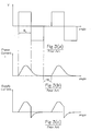
- Figure 3 shows typical waveforms for an operating cycle of the circuit shown in Figure 2.
- Figure 3(a) shows the voltage being applied for the duration of the conduction angle ⁇ c when the switches 21 and 22 are closed.
- Figure 3(b) shows the current in the phase winding 16 rising to a peak and then falling slightly.
- the switches are opened and the current transfers to the diodes, placing the inverted link voltage across the winding and hence forcing down the flux and the current to zero.
- the diodes cease to conduct and the circuit is inactive until the start of a subsequent conduction period.
- the current on the DC link reverses when the switches are opened, as shown in Figure 3(c), and the returned current represents energy being returned to the supply.
- the shape of the current waveform varies depending on the operating point of the machine and on the switching strategy adopted. As is well-known and described in, for example, the Stephenson paper cited above, low-speed operation generally involves the use of current chopping to contain the peak currents, and switching off the switches non-simultaneously gives an operating mode generally known as "freewheeling".
- the performance of a switched reluctance machine depends, in part, on the accurate timing of phase energisation with respect to rotor position. Detection of rotor position is conventionally achieved by using a transducer 15, shown schematically in Figure 1, such as a rotating toothed disk mounted on the machine rotor, which co-operates with an optical or magnetic sensor mounted on the stator. A pulse train indicative of rotor position relative to the stator is generated and supplied to control circuitry, allowing accurate phase energisation.
- This system is simple and works well in many applications.
- the rotor position transducer increases the overall cost of assembly, adds extra electrical connections to the machine and is, therefore, a potential source of unreliability.
- phase flux-linkage i.e. the integral of applied voltage with respect to time
- current in one or more phases can be monitored.
- Position is calculated using knowledge of the variation in inductance of the machine as a function of angle and current.
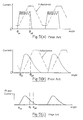
- This characteristic can be stored as a flux-linkage/angle/current table and is depicted graphically in Figure 4. The storage of this data involves the use of a large memory array and/or additional system overheads for interpolation of data between stored points.
- Chopping control is illustrated graphically in Figure 5(a) in which the current and inductance waveforms are shown over a phase inductance period. (Note that the variation of inductance is depicted in idealised form.) These methods usually employ diagnostic energisation pulses in non-torque-productive phases (i.e. those phases which are not energised directly from the power supply at a particular moment).
- phase inductance cycle of a switched reluctance machine is the period of the variation of inductance for the, or each, phase, for example between maxima when the rotor poles and the relevant respective stator poles are fully aligned.
- Figure 5(a) shows the inductance profile in idealised form, whereas in practice the comers of the profile are rounded due to flux fringing in the air and to saturation of the ferromagnetic paths.
- phase current waveform of a switched reluctance machine in single-pulse mode is related to the inductance profile of the phase winding.
- start of the rising portion of the inductance profile which is due to the onset of overlap between the stator and rotor poles, corresponds to the rollover when the phase current changes from rising to falling in the phase inductance cycle.
- European Patent Application EP1109309A discusses this phenomenon and uses the natural peak in current, in single-pulse operation, as the basis of a rotor position detection method.
- the magnitude of the waveform of the parameter being employed for rotor position detection must be large enough to allow the chosen algorithm to work reliably. While this is not a problem when the machine is on full load or a significant fraction of it, if the machine is called on to operate at a particular speed at no-load or a very small output, the flux or current (for example) is often so small that the position detection algorithms are at best error prone and often completely fail, and the control system consequently loses control of the machine. In many applications this is unacceptable.
- an embodiment of the invention provides a method of operating a polyphase electrical machine, the method comprising: reducing the duty of at least one phase for a given output demand; and increasing the duty of the other phase(s) to compensate for the reduction in the duty of the at least one phase for the given output demand, in which the variation in the duty of the phases allows, for example, advantageous rotor position detection at low loads.
- the duty of the phase is its contribution to the overall output of the machine made up of the plurality of phase outputs. Under ideal normal running conditions, the duty of each phase is equal.
- This embodiment of the invention varies the duty in at least one of the phases and adjusts the output in the others to compensate. This facilitates robust and cost-effective rotor position detection over a wider range of system loads than previously thought possible.
- the duty of the at least one phase is reduced to zero.
- the method of the invention may be invoked whenever a threshold of a parameter is reached, or after the threshold has been passed for a predetermined period or for a given number of times within a predetermined period. This addresses the issue of the volatility with which the method is invoked or reverts to a conventional operating technique.
- the parameter e.g. phase current or flux-linkage
- the parameter can be used to determine the position of a machine rotor relative to its stator in a sensorless rotor position detection technique.
- the invention allowing the current fed to the remaining phase(s) to be increased, raises the parameter readings above the threshold at which they are otherwise prone to error.
- the method includes sensing a parameter of the machine; determining when the parameter passes a predetermined threshold; and reducing the duty of the at least one phase in response.
- Reduction in the duty of a phase can be introduced gradually as, for example, a set of thresholds in the parameter signal level is each passed.
- the duty of each phase can be reduced in turn as such a set of thresholds is each passed.
- the illustrative embodiment to be described uses a 3-phase switched reluctance drive in the motoring mode, but any phase number greater than one could be used, with the drive in either motoring or generating mode.
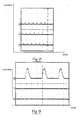
- Figure 6 shows the measured phase current waveforms of an exemplary 3-phase switched reluctance machine operating near its full load of 22kW at 4000 rev/min. As would be expected, the currents are balanced. The magnitude of the phase current, approximately 78A peak, is adequate for the controller to use a position detection routine in a satisfactory way to determine the rotor position.
- Figure 7 shows the phase current waveforms of the same machine operating at 2% of full load torque with phase currents of approximately 5A peak. Although the currents are still approximately balanced, relatively small disturbances in the load can cause significant transient unbalance in the currents. The magnitude of the current has now fallen to such an extent that the position detection routines cannot work reliably.
- Figure 8 shows the effect of a further very small reduction in demand, which leads to the controller losing control and ceasing to commutate the phases correctly. Although routines are known for recovery from such a condition, there is an inevitable disturbance to the output of the machine, which may be unacceptable to the user.
- the invention can be put into effect before this point is reached.
- the machine is caused to operate on fewer phases than the total number of phases in the machine. For a given load demand, this causes the machine to work much harder in the phases still operating, thus increasing the currents in these phases.
- the machine is operated on only one of the three phases.
- Figure 9 shows the current waveform of that one phase, where the speed and output torque are the same as Figure 7.
- the peak current has gone up from 5A to 15A, enabling the position detection algorithm to operate with a much greater safety margin.
- the duty is now solely on one of the phases because the duty of the remaining phases is reduced to zero.
- This method of operation greatly increases the robustness of the position detection algorithms and enables them to operate successfully over a much wider range of load demand than would otherwise be possible. While the torque ripple will have increased, since only one phase is contributing to the output instead of three, this is preferable to sudden loss of torque if the commutation fails due to the sensorless algorithms losing track of position.
- the invention can be implemented in response to a trigger event.
- This event can be, for example, the load demand falling below a pre-determined level or the phase current falling below a pre-determined level, or some other event which correlates with the position detection algorithms nearing the edge of their stable operating region.
- a threshold is set for phase current. In other examples of drives, measurement of phase current may not be convenient or possible, so a threshold of, say, load demand, can be used.
- FIG 10 shows a system for implementing the method in which one form of the invention is embodied.
- a power converter 13 which is typically the same as that shown in Figure 1, is provided for controlling the switched reluctance machine.
- Controlling the converter 13 is a controller 140 which, in this embodiment, incorporates a processor, particularly a digital signal processor 144, e.g. one from the Analog Devices 2181 family, and associated program and data memory 146.
- a processor particularly a digital signal processor 144, e.g. one from the Analog Devices 2181 family
- Alternative embodiments could incorporate a microprocessor or other form of programmable device, as are well known in the art.
- the processor runs in a conventional way according to the program code stored in the memory 146 to execute the method of the present invention.
- FIG 11 shows a flow chart outlining the method of control which implements an embodiment of the invention in the controller 140.
- the controller samples the phase current by a known method, e.g. by examining the output from the current transducer 18.
- the controller executes a test to check if the peak phase current has fallen below a set threshold. This threshold may be fixed for any drive, or could be a function of speed. If the test is not met, the controller operates as normal, using all the phases. If the test is met, it indicates that the machine should be operated on a reduced number of phases and the active number of phases is then set to the predetermined number. Of course, the reduced number of phases has to include the phase in relation to which the current sensor 18 is arranged. In a preferred form, the number of active phases is reduced to one, giving the maximum increase in the phase quantities in that remaining phase.
- the system requires a succession of current values to be at or below the threshold before machine operation is continued on the reduced number of phases. This avoids an inappropriate change in control strategy in the event of a spurious reading.
- an assessment of the phase current over a given period after the threshold has been reached could be used to the same end in order to avoid a control regime change that is unacceptably volatile.
- a more sophisticated arrangement is to successively reduce the number of operating phases, thus keeping the maximum number operating for any load. As the load is further reduced and the current again falls to the threshold, the number of operating phases is again reduced. So, for example, a 4-phase system could operate on 3, 2 and 1 phases as the load is gradually reduced. In this case, a set of thresholds are established at which a decision on removing or reintroducing a phase can be taken. Again, the volatility of removing and reintroducing phases when a current is at or about a given threshold can be addressed by only taking action if the current falls below a threshold for a given period or a number of times in a given period.
- a further test is implemented at 155 to determine if the current has fallen below the next threshold in a set of thresholds. If that test is met, control loops back to 154 where the phase number is further reduced, if that is possible. When the number of operating phases has been determined, control passes to step 156 as before and the chosen sensorless algorithm is implemented to determine rotor position and the control continues at step 158 in the usual fashion.
- the illustrated machine has three phases, but one skilled in the art will realise that a machine with different phase numbers or pole combinations could be used, since the invention is not specific to any particular machine topology.
- a four-phase machine with 8 stator poles and 6 rotor poles could be operated on one phase, say Phase A, or on two phases, say Phases A and B, or Phases A and C. The latter would have the advantage of providing smoother torque output.
- the method may be applied with equal benefit to machines operating as motors or as generators and to any machine where phase-related parameters are used for rotor position detection.
- the method is not specific to one genre of position control algorithms.
- each phase is described here as being either a full contributor to the machine output (electrical or mechanical) or removed from operation completely.
- reducing the duty in the other phases only partially and compensating for that reduction in duty in the remaining phase(s) to which the parameter sensor is connected may sufficiently increase the signal available for sensing.
Landscapes
- Engineering & Computer Science (AREA)
- Power Engineering (AREA)
- Control Of Electric Motors In General (AREA)
Applications Claiming Priority (2)
| Application Number | Priority Date | Filing Date | Title |
|---|---|---|---|
| GBGB0325955.3A GB0325955D0 (en) | 2003-11-06 | 2003-11-06 | Operation of an electrical machine |
| GB0325955 | 2003-11-06 |
Publications (2)
| Publication Number | Publication Date |
|---|---|
| EP1530283A1 true EP1530283A1 (fr) | 2005-05-11 |
| EP1530283B1 EP1530283B1 (fr) | 2008-03-19 |
Family
ID=29726086
Family Applications (1)
| Application Number | Title | Priority Date | Filing Date |
|---|---|---|---|
| EP04256902A Expired - Lifetime EP1530283B1 (fr) | 2003-11-06 | 2004-11-08 | Opération d'une machine électrique |
Country Status (6)
| Country | Link |
|---|---|
| US (1) | US7057362B2 (fr) |
| EP (1) | EP1530283B1 (fr) |
| KR (1) | KR20050043658A (fr) |
| CN (1) | CN100435472C (fr) |
| DE (1) | DE602004012514T2 (fr) |
| GB (1) | GB0325955D0 (fr) |
Cited By (1)
| Publication number | Priority date | Publication date | Assignee | Title |
|---|---|---|---|---|
| WO2010126923A3 (fr) * | 2009-04-30 | 2011-11-10 | University Of Akron | Estimation de position au démarrage et à de faibles vitesses dans des machines à réluctance commutées triphasées |
Families Citing this family (18)
| Publication number | Priority date | Publication date | Assignee | Title |
|---|---|---|---|---|
| GB0424367D0 (en) * | 2004-11-03 | 2004-12-08 | Switched Reluctance Drives Ltd | Operation of an electrical machine |
| US7745949B2 (en) * | 2008-02-26 | 2010-06-29 | General Electric Company | Method and apparatus for assembling electrical machines |
| GB0804866D0 (en) * | 2008-03-17 | 2008-04-16 | Rolls Royce Plc | Electrical machine arrangement |
| US8143825B2 (en) * | 2008-10-24 | 2012-03-27 | Marvell World Trade Ltd. | Determining stuck conditions for electric motors using inductive sensing |
| US8277198B2 (en) * | 2008-11-13 | 2012-10-02 | Marvell International Ltd. | Fan motor control systems |
| US8807956B2 (en) | 2008-11-13 | 2014-08-19 | Marvell World Trade Ltd. | Apparatus and method for controlling speed of a fan via a first control module connected by a cable and/or conductors between a motor and a second control module |
| US20130207588A1 (en) * | 2012-02-15 | 2013-08-15 | Samsung Electro-Mechanics Co., Ltd. | Initial driving apparatus and method of two-phase srm |
| US8975855B2 (en) * | 2012-07-23 | 2015-03-10 | Caterpillar Inc. | Compensating hysteresis bands to hold specified switching frequency |
| JP6070925B2 (ja) * | 2012-08-24 | 2017-02-01 | 富士電機株式会社 | 電動機駆動システム |
| CN102904515B (zh) * | 2012-10-22 | 2015-03-04 | 中国矿业大学 | 开关磁阻发电机无位置传感器控制方法 |
| DE102013100500B4 (de) * | 2013-01-18 | 2021-02-25 | Linde Material Handling Gmbh | Elektrische Hydraulikpumpenvorrichtung eines Flurförderzeugs |
| TWI695447B (zh) | 2013-11-13 | 2020-06-01 | 布魯克斯自動機械公司 | 運送設備 |
| WO2015073647A1 (fr) | 2013-11-13 | 2015-05-21 | Brooks Automation, Inc. | Mécanisme d'entraînement de robot scellé |
| US10348172B2 (en) | 2013-11-13 | 2019-07-09 | Brooks Automation, Inc. | Sealed switched reluctance motor |
| KR20230116962A (ko) | 2013-11-13 | 2023-08-04 | 브룩스 오토메이션 인코퍼레이티드 | 브러쉬리스 전기 기계 제어 방법 및 장치 |
| US10897217B2 (en) * | 2018-08-21 | 2021-01-19 | Caterpillar Inc. | Switched reluctance motor control system |
| GB2604136B (en) * | 2021-02-25 | 2023-09-13 | Dyson Technology Ltd | Method of controlling a three-phase permanent-magnet motor |
| CN116660744A (zh) * | 2022-02-21 | 2023-08-29 | 华晨宝马汽车有限公司 | 电机运行状态监测方法和系统 |
Citations (3)
| Publication number | Priority date | Publication date | Assignee | Title |
|---|---|---|---|---|
| DE3042927A1 (de) * | 1980-11-14 | 1982-06-03 | Parker, Louis W., 33305 Fort Lauderdale, Fla. | Steuerschaltung bei einem dreiphasendrehstrommotor |
| US4868478A (en) * | 1986-10-10 | 1989-09-19 | Ems Electronic Motor Systems Ab | Motor energizing circuit |
| EP1109309A2 (fr) * | 1999-12-15 | 2001-06-20 | Switched Reluctance Drives Limited | Surveillance de la position du rotor d'un entraínement à réluctance |
Family Cites Families (22)
| Publication number | Priority date | Publication date | Assignee | Title |
|---|---|---|---|---|
| US4434389A (en) * | 1980-10-28 | 1984-02-28 | Kollmorgen Technologies Corporation | Motor with redundant windings |
| SE464213B (sv) | 1989-07-28 | 1991-03-18 | Electrolux Mecatronik Ab | Foerfarande och anordning foer sensorfri styrning av en eluktansmotor |
| GB9211685D0 (en) * | 1992-06-03 | 1992-07-15 | Switched Reluctance Drives Ltd | Sensorless rotor position measurement |
| US6051942A (en) * | 1996-04-12 | 2000-04-18 | Emerson Electric Motor Co. | Method and apparatus for controlling a switched reluctance machine |
| GB9607688D0 (en) * | 1996-04-12 | 1996-06-12 | Switched Reluctance Drives Ltd | Current shaping in reluctance machines |
| US6107772A (en) * | 1997-09-26 | 2000-08-22 | Dana Corporation | Sensorless switched reluctance motor control |
| US6472842B1 (en) * | 1997-10-03 | 2002-10-29 | The Texas A&M University System | Self-tuning control of switched-reluctance motor drive system |
| US6731083B2 (en) * | 1998-06-02 | 2004-05-04 | Switched Reluctance Drives, Ltd. | Flux feedback control system |
| SG106576A1 (en) * | 1999-01-11 | 2004-10-29 | Switched Reluctance Drives Ltd | Rotor position detection in switched reluctance machines |
| GB9903401D0 (en) * | 1999-02-15 | 1999-04-07 | Switched Reluctance Drives Ltd | Control of switched reluctance machines |
| US6366865B1 (en) * | 1999-11-03 | 2002-04-02 | Motorola, Inc. | Apparatus and method for estimating the coil resistance in an electric motor |
| GB0007422D0 (en) * | 2000-03-27 | 2000-05-17 | Switched Reluctance Drives Ltd | Position detection of switched reluctance machines |
| GB0020501D0 (en) * | 2000-08-18 | 2000-10-11 | Switched Reluctance Drives Ltd | Apparatus and method for controlling an electric machine |
| US6897591B2 (en) * | 2001-03-26 | 2005-05-24 | Emerson Electric Co. | Sensorless switched reluctance electric machine with segmented stator |
| US6456031B1 (en) * | 2001-01-19 | 2002-09-24 | Delphi Technologies, Inc. | Rotor position estimation for switched reluctance machines |
| US6448736B1 (en) * | 2001-04-16 | 2002-09-10 | Motorola, Inc. | Method for controlling switched reluctance motor, and controller |
| US6646407B2 (en) * | 2001-06-08 | 2003-11-11 | General Motors Corporation | Electric motor control having DC-DC converter and method of using same |
| US6653811B2 (en) * | 2001-08-08 | 2003-11-25 | A. O. Smith Corporation | Switched reluctance motor and method and apparatus for aligning the rotor thereof |
| US6623245B2 (en) * | 2001-11-26 | 2003-09-23 | Shurflo Pump Manufacturing Company, Inc. | Pump and pump control circuit apparatus and method |
| GB0130237D0 (en) * | 2001-12-18 | 2002-02-06 | Switched Reluctance Drives Ltd | Rotor position detection of a switched reluctance drive |
| US6674260B1 (en) * | 2002-06-20 | 2004-01-06 | Hewlett-Packard Development Company, L.P. | DC motor control |
| US6801012B1 (en) * | 2003-03-31 | 2004-10-05 | Delphi Technologies, Inc. | Sensorless control of switched reluctance electric machines |
-
2003
- 2003-11-06 GB GBGB0325955.3A patent/GB0325955D0/en not_active Ceased
-
2004
- 2004-10-29 US US10/977,027 patent/US7057362B2/en not_active Expired - Lifetime
- 2004-11-02 CN CNB2004100868595A patent/CN100435472C/zh not_active Expired - Fee Related
- 2004-11-04 KR KR1020040089147A patent/KR20050043658A/ko not_active Withdrawn
- 2004-11-08 DE DE602004012514T patent/DE602004012514T2/de not_active Expired - Lifetime
- 2004-11-08 EP EP04256902A patent/EP1530283B1/fr not_active Expired - Lifetime
Patent Citations (3)
| Publication number | Priority date | Publication date | Assignee | Title |
|---|---|---|---|---|
| DE3042927A1 (de) * | 1980-11-14 | 1982-06-03 | Parker, Louis W., 33305 Fort Lauderdale, Fla. | Steuerschaltung bei einem dreiphasendrehstrommotor |
| US4868478A (en) * | 1986-10-10 | 1989-09-19 | Ems Electronic Motor Systems Ab | Motor energizing circuit |
| EP1109309A2 (fr) * | 1999-12-15 | 2001-06-20 | Switched Reluctance Drives Limited | Surveillance de la position du rotor d'un entraínement à réluctance |
Non-Patent Citations (1)
| Title |
|---|
| MATSUO T ET AL: "Rotor position detection scheme for synchronous reluctance motor based on current measurements", INDUSTRY APPLICATIONS SOCIETY ANNUAL MEETING, 1994., CONFERENCE RECORD OF THE 1994 IEEE DENVER, CO, USA 2-6 OCT. 1994, NEW YORK, NY, USA,IEEE, 2 October 1994 (1994-10-02), pages 627 - 634, XP010124055, ISBN: 0-7803-1993-1 * |
Cited By (3)
| Publication number | Priority date | Publication date | Assignee | Title |
|---|---|---|---|---|
| WO2010126923A3 (fr) * | 2009-04-30 | 2011-11-10 | University Of Akron | Estimation de position au démarrage et à de faibles vitesses dans des machines à réluctance commutées triphasées |
| US8810188B2 (en) | 2009-04-30 | 2014-08-19 | Iqbal Husain | Position estimation at starting and lower speeds in three-phase switched reluctance machines |
| EA020858B1 (ru) * | 2009-04-30 | 2015-02-27 | Юниверсити Оф Акрон | Оценка положения при пуске и низких скоростях в трехфазных коммутируемых реактивных электродвигателях |
Also Published As
| Publication number | Publication date |
|---|---|
| EP1530283B1 (fr) | 2008-03-19 |
| US20050099152A1 (en) | 2005-05-12 |
| DE602004012514D1 (de) | 2008-04-30 |
| US7057362B2 (en) | 2006-06-06 |
| CN100435472C (zh) | 2008-11-19 |
| KR20050043658A (ko) | 2005-05-11 |
| DE602004012514T2 (de) | 2009-04-23 |
| GB0325955D0 (en) | 2003-12-10 |
| CN1614870A (zh) | 2005-05-11 |
Similar Documents
| Publication | Publication Date | Title |
|---|---|---|
| EP1530283B1 (fr) | Opération d'une machine électrique | |
| EP1471629B1 (fr) | Détermination de la position du rotor d'un moteur à reluctance | |
| EP1484834B1 (fr) | Détection de position du rotor d'un moteur à reluctance commutée | |
| CA2279540C (fr) | Commande de moteur a cc sans balai | |
| US6972533B2 (en) | Control of a switched reluctance drive | |
| JP4688285B2 (ja) | リラクタンス駆動装置の回転子位置の監視 | |
| EP1014556A1 (fr) | Régulation des machines à réluctance commutées | |
| EP1324484B1 (fr) | Détection de la position pour un dispositif de réluctance commutée | |
| EP1553691B1 (fr) | Détection de la position du rotor d'une machine électrique | |
| EP1655831B1 (fr) | Operation d'un machine électrique | |
| US7388345B2 (en) | Rotor position detection in an electrical machine |
Legal Events
| Date | Code | Title | Description |
|---|---|---|---|
| PUAI | Public reference made under article 153(3) epc to a published international application that has entered the european phase |
Free format text: ORIGINAL CODE: 0009012 |
|
| AK | Designated contracting states |
Kind code of ref document: A1 Designated state(s): AT BE BG CH CY CZ DE DK EE ES FI FR GB GR HU IE IS IT LI LU MC NL PL PT RO SE SI SK TR |
|
| AX | Request for extension of the european patent |
Extension state: AL HR LT LV MK YU |
|
| 17P | Request for examination filed |
Effective date: 20051108 |
|
| AKX | Designation fees paid |
Designated state(s): DE FR GB IT |
|
| GRAP | Despatch of communication of intention to grant a patent |
Free format text: ORIGINAL CODE: EPIDOSNIGR1 |
|
| RIC1 | Information provided on ipc code assigned before grant |
Ipc: H02P 6/18 20060101ALI20070822BHEP Ipc: H02P 25/08 20060101AFI20070822BHEP |
|
| GRAS | Grant fee paid |
Free format text: ORIGINAL CODE: EPIDOSNIGR3 |
|
| GRAA | (expected) grant |
Free format text: ORIGINAL CODE: 0009210 |
|
| AK | Designated contracting states |
Kind code of ref document: B1 Designated state(s): DE FR GB IT |
|
| REG | Reference to a national code |
Ref country code: GB Ref legal event code: FG4D |
|
| REF | Corresponds to: |
Ref document number: 602004012514 Country of ref document: DE Date of ref document: 20080430 Kind code of ref document: P |
|
| ET | Fr: translation filed | ||
| PLBE | No opposition filed within time limit |
Free format text: ORIGINAL CODE: 0009261 |
|
| STAA | Information on the status of an ep patent application or granted ep patent |
Free format text: STATUS: NO OPPOSITION FILED WITHIN TIME LIMIT |
|
| 26N | No opposition filed |
Effective date: 20081222 |
|
| REG | Reference to a national code |
Ref country code: FR Ref legal event code: CD |
|
| REG | Reference to a national code |
Ref country code: DE Ref legal event code: R082 Ref document number: 602004012514 Country of ref document: DE Representative=s name: UEXKUELL & STOLBERG, DE |
|
| REG | Reference to a national code |
Ref country code: DE Ref legal event code: R081 Ref document number: 602004012514 Country of ref document: DE Owner name: NIDEC SR DRIVES LTD., GB Free format text: FORMER OWNER: SWITCHED RELUCTANCE DRIVES LTD., HARROGATE, GB Effective date: 20121217 Ref country code: DE Ref legal event code: R082 Ref document number: 602004012514 Country of ref document: DE Representative=s name: UEXKUELL & STOLBERG, DE Effective date: 20121217 Ref country code: DE Ref legal event code: R081 Ref document number: 602004012514 Country of ref document: DE Owner name: NIDEC SR DRIVES LTD., HARROGATE, GB Free format text: FORMER OWNER: SWITCHED RELUCTANCE DRIVES LTD., HARROGATE, NORTH YORKSHIRE, GB Effective date: 20121217 Ref country code: DE Ref legal event code: R082 Ref document number: 602004012514 Country of ref document: DE Representative=s name: UEXKUELL & STOLBERG PARTNERSCHAFT VON PATENT- , DE Effective date: 20121217 |
|
| REG | Reference to a national code |
Ref country code: FR Ref legal event code: PLFP Year of fee payment: 12 |
|
| REG | Reference to a national code |
Ref country code: FR Ref legal event code: PLFP Year of fee payment: 13 |
|
| REG | Reference to a national code |
Ref country code: FR Ref legal event code: PLFP Year of fee payment: 14 |
|
| PG25 | Lapsed in a contracting state [announced via postgrant information from national office to epo] |
Ref country code: IT Free format text: LAPSE BECAUSE OF NON-PAYMENT OF DUE FEES Effective date: 20191108 |
|
| PGFP | Annual fee paid to national office [announced via postgrant information from national office to epo] |
Ref country code: FR Payment date: 20211109 Year of fee payment: 18 Ref country code: GB Payment date: 20211026 Year of fee payment: 18 Ref country code: DE Payment date: 20211130 Year of fee payment: 18 |
|
| REG | Reference to a national code |
Ref country code: DE Ref legal event code: R119 Ref document number: 602004012514 Country of ref document: DE |
|
| GBPC | Gb: european patent ceased through non-payment of renewal fee |
Effective date: 20221108 |
|
| PG25 | Lapsed in a contracting state [announced via postgrant information from national office to epo] |
Ref country code: GB Free format text: LAPSE BECAUSE OF NON-PAYMENT OF DUE FEES Effective date: 20221108 Ref country code: DE Free format text: LAPSE BECAUSE OF NON-PAYMENT OF DUE FEES Effective date: 20230601 |
|
| PG25 | Lapsed in a contracting state [announced via postgrant information from national office to epo] |
Ref country code: FR Free format text: LAPSE BECAUSE OF NON-PAYMENT OF DUE FEES Effective date: 20221130 |