EP1530406A1 - Wandmontierter Mikrowellenofen - Google Patents
Wandmontierter Mikrowellenofen Download PDFInfo
- Publication number
- EP1530406A1 EP1530406A1 EP04253480A EP04253480A EP1530406A1 EP 1530406 A1 EP1530406 A1 EP 1530406A1 EP 04253480 A EP04253480 A EP 04253480A EP 04253480 A EP04253480 A EP 04253480A EP 1530406 A1 EP1530406 A1 EP 1530406A1
- Authority
- EP
- European Patent Office
- Prior art keywords
- inlet port
- microwave oven
- exhaust passage
- type microwave
- hood
- Prior art date
- Legal status (The legal status is an assumption and is not a legal conclusion. Google has not performed a legal analysis and makes no representation as to the accuracy of the status listed.)
- Withdrawn
Links
Images


Classifications
-
- F—MECHANICAL ENGINEERING; LIGHTING; HEATING; WEAPONS; BLASTING
- F24—HEATING; RANGES; VENTILATING
- F24C—DOMESTIC STOVES OR RANGES ; DETAILS OF DOMESTIC STOVES OR RANGES, OF GENERAL APPLICATION
- F24C15/00—Details
- F24C15/20—Removing cooking fumes
-
- H—ELECTRICITY
- H05—ELECTRIC TECHNIQUES NOT OTHERWISE PROVIDED FOR
- H05B—ELECTRIC HEATING; ELECTRIC LIGHT SOURCES NOT OTHERWISE PROVIDED FOR; CIRCUIT ARRANGEMENTS FOR ELECTRIC LIGHT SOURCES, IN GENERAL
- H05B6/00—Heating by electric, magnetic or electromagnetic fields
- H05B6/64—Heating using microwaves
- H05B6/6426—Aspects relating to the exterior of the microwave heating apparatus, e.g. metal casing, power cord
- H05B6/6429—Aspects relating to mounting assemblies of wall-mounted microwave ovens
-
- F—MECHANICAL ENGINEERING; LIGHTING; HEATING; WEAPONS; BLASTING
- F24—HEATING; RANGES; VENTILATING
- F24C—DOMESTIC STOVES OR RANGES ; DETAILS OF DOMESTIC STOVES OR RANGES, OF GENERAL APPLICATION
- F24C15/00—Details
- F24C15/20—Removing cooking fumes
- F24C15/2042—Devices for removing cooking fumes structurally associated with a cooking range e.g. downdraft
-
- H—ELECTRICITY
- H05—ELECTRIC TECHNIQUES NOT OTHERWISE PROVIDED FOR
- H05B—ELECTRIC HEATING; ELECTRIC LIGHT SOURCES NOT OTHERWISE PROVIDED FOR; CIRCUIT ARRANGEMENTS FOR ELECTRIC LIGHT SOURCES, IN GENERAL
- H05B6/00—Heating by electric, magnetic or electromagnetic fields
- H05B6/64—Heating using microwaves
- H05B6/642—Cooling of the microwave components and related air circulation systems
- H05B6/6423—Cooling of the microwave components and related air circulation systems wherein the microwave oven air circulation system is also used as air extracting hood
Definitions
- the present invention relates to wall mounted-type microwave ovens, and more particularly, to a wall mounted-type microwave oven provided with a hood having an inlet port with an improved structure, thus effectively drawing exhaust gases and food odors produced from a plurality of gas burners placed below the hood.
- a wall mounted-type microwave oven is mounted to a wall of a kitchen above a plurality of gas burners.
- the wall mounted-type microwave oven collaterally serves to exhaust gases, fumes, and food odors produced from the gas burners, which are positioned under the microwave oven, in addition to cooking food using high-frequency electromagnetic waves.
- the wall mounted-type microwave oven includes a cabinet to define an external appearance thereof.
- the cabinet is partitioned into a cooking cavity and a machine room, and the food to be cooked is disposed in the cooking cavity.
- An exhaust passage is defined between an outside of the cooking cavity and the cabinet. Further, an exhaust fan is provided to an upper portion of the exhaust passage to draw exhaust gases and food odors produced from the plurality of gas burners into the exhaust passage, and to discharge the exhaust gases and the food odors to the outside of the wall mounted-type microwave oven.
- a hood having an inlet port is mounted to a bottom portion of the cabinet.
- the inlet port of the hood communicates with the exhaust passage so that the exhaust gases and the food odors produced from the plurality of gas burners flow through the inlet port into the exhaust passage.
- the exhaust passage is provided at a side of the cabinet and the inlet port through which exhaust gases and food odors are drawn into the exhaust passage is constructed to have a constant width.
- a stronger suction force of the exhaust fan acts on the gas burners placed near the exhaust passage in comparison to gas burners placed far from the exhaust passage. Therefore, exhaust gases produced from gas burners placed near the exhaust passage are smoothly drawn into the exhaust passage, whereas exhaust gases produced from gas burners placed far from the exhaust passage are not smoothly drawn into the exhaust passage.
- the conventional wall mounted-type microwave oven presents a problem because the wall mounted-type microwave oven does not effectively draw and discharge exhaust gases produced from all gas burners placed below the hood.
- the present invention provides a wall mounted-type microwave oven provided with a hood having an inlet port with an improved structure, thus effectively drawing exhaust gases and food odors produced from a plurality of gas burners placed below the hood.
- a wall mounted-type microwave oven including a cabinet having an exhaust passage, and a hood mounted to a bottom portion of the cabinet and having at least one inlet port to communicate with the exhaust passage, the inlet port being formed so that a width of an end portion of the inlet port near the exhaust passage is less than a width of an end portion of the inlet port far from the exhaust passage.
- the inlet port may be shaped so that a width thereof is decreased at a predetermined ratio in a direction towards the exhaust passage.
- the inlet port may comprise a plurality of inlet ports, which are horizontally arranged on the hood.
- the inlet port may have a trapezoidal shape according to an aspect of the present invention.
- a wall mounted-type microwave oven including a cabinet having an exhaust passage, an exhaust fan provided at a predetermined location in relation to the exhaust passage, and a hood mounted to a bottom portion of the cabinet with an inlet port horizontally provided to a predetermined portion of the hood to communicate with the exhaust passage, where the inlet port is formed so that an area of a portion of the inlet port on which a weaker suction force of the exhaust fan acts is larger than an area of a portion of the inlet port on which a stronger suction force of the exhaust fan acts.
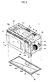
- Figures 1 and 2 respectively show an exploded front perspective view and an exploded bottom perspective view of a wall mounted-type microwave oven having a hood according to a first embodiment of the present invention.
- the wall mounted-type microwave oven 1 includes a cabinet 10, which is box-shaped, and defines an external appearance of the wall mounted-typed microwave oven 1.
- the cabinet 10 is partitioned into a cooking cavity 11 and a machine room 12.
- An exhaust passage 13 is provided between a left side plate 10a of the cabinet 10 and a left side plate 11a of the cooking cavity 11.
- the exhaust passage 13 guides exhaust gases and fumes produced from a cooking apparatus 50 (shown in Figure 5) located below the cabinet 10 that includes gas burners 51 and 52 to discharge the exhaust gases and the fumes to an outside of the wall mounted-type microwave oven.
- a cooking apparatus 50 shown in Figure 5
- an exhaust fan 14 and a fan motor 15 are installed to an upper rear portion of the cabinet 10 to discharge the exhaust gases and the fumes, which flow along the exhaust passage 13, to the outside of the wall mounted-type microwave oven.
- the exhaust fan 14 is mounted to a left side of the fan motor 15, and is operated by the fan motor 15. Further, a cooling fan 16 is mounted to a right side of the fan motor 15 to supply air to the machine room 12, thus cooling electrical devices including a magnetron 17, a high-voltage transformer 18, and a condenser 19 which are installed in the machine room 12.
- a front suction grill 20 is provided to an upper front portion of the machine room 12, and a front discharging grill 21 is provided to an upper front portion of the cooking cavity 11.
- a plurality of perforations 22 are provided to a right side plate 11b of the cooking cavity 11, which partitions the cooking cavity 11 and the machine room 12 from each other. Further, a plurality of perforations 23 are provided to a top plate 11c of the cooking cavity 11.
- a hood 30 having an inlet port 31 is mounted to a bottom portion of the cabinet 10.
- the hood 30 is mounted to the bottom portion of the cabinet 10 spaced from a bottom plate 11d (shown in Figure 2) of the cooking cavity 11 by a predetermined distance, thus allowing air passing through the inlet port 31 of the hood 30 to flow into the exhaust passage 13.
- the inlet port 31 is horizontally formed spaced from left and right edges of the hood 30 by predetermined distances. According to an aspect of the present invention, a right edge 31a of the inlet port 31 is the longest, while a left edge 31b of the inlet port 31 is the shortest.
- the right edge 31a of the inlet port 31 is formed to be longer than the left edge 31b of the inlet port 31 because a stronger suction force of the exhaust fan 14 acts on a portion around the left edge 31b of the inlet port 31 that is near the exhaust passage 13 in comparison to a portion around the right edge 31a of the inlet port 31, which is far from the exhaust passage 13.
- a stronger suction force of the exhaust fan 14 acts on the portion around the left edge 31b of the inlet port 31
- a larger amount of exhaust gas is drawn to the portion around the left edge 31b of the inlet port 31 in comparison to the portion around the right edge 31a of the inlet port 31.
- the inlet port 31 is constructed so that the right edge 31a far from the exhaust passage 13 is the longest, and the left edge 31b near the exhaust passage 13 is the shortest.
- the length from a front edge 31c to a rear edge 31d of the inlet port 31, that is, a width of the inlet port 31, is gradually and evenly decreased in a direction from the right edge 31a to the left edge 31b of the inlet port 31.
- the wall mounted-type microwave oven 1 has one trapezoid inlet port 31.
- an area of the portion around the left edge 31b of the inlet port 31 towards which the stronger suction force of the exhaust fan 14 acts is smaller, while an area of the portion around the right edge 31a of the inlet port 31 on which the weaker suction force of the exhaust fan 14 acts is larger.
- the exhaust gases produced from the gas burners 51 placed below the left edge 31b of the inlet port 31, and the exhaust gases produced from the gas burners 52 placed below the right edge 31a of the inlet port 31 are evenly drawn to the exhaust passage 13 through the inlet port 31.
- the exhaust gases entering the exhaust passage 13 are discharged to the outside after passing through the exhaust fan 14.
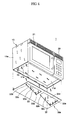
- Figures 3 and 4 respectively show an exploded front perspective view and an exploded bottom perspective view of a wall mounted-type microwave oven having a hood, according to a second embodiment of the present invention.
- the wall mounted-type microwave oven 1 according to the second embodiment includes the cabinet 10 with the hood 30a mounted to the bottom portion of the cabinet 10.
- First and second inlet ports 32 and 33 which have the same shape as the inlet port 31 of the wall mounted-type microwave oven 1 of the first embodiment, are provided on right and left sides of the hood 30a, respectively. Accordingly, the general construction of the wall mounted-type microwave oven 1 according to the second embodiment remains the same as the wall mounted-type microwave oven 1 according to the first embodiment, with the exception of a plurality of inlet ports 32 and 33 provided in the hood 30a.
- the first and second inlet ports 32 and 33 each having a trapezoidal shape, are placed on the right and left sides of the hood 30a spaced from each other by a predetermined distance.
- the first inlet port 32 is formed so that a right edge 32a of the first inlet port 32 is longer than a left edge 32b of the first inlet port 32.
- a length from a front edge 32c to a rear edge 32d of the first inlet port 32, that is, a width of the first inlet port 32 is gradually decreased in a direction from the right edge 32a to the left edge 32b of the first inlet port 32.
- a portion around the left edge 32b of the first inlet port 32 near the exhaust passage 13 has a smaller area than a portion around the right edge 32a of the first inlet port 32, which is far from the exhaust passage 13.
- the second inlet port 33 provided on the left side of the hood 30a is formed so that a right edge 33a of the second inlet port 33 is longer than a left edge 33b of the second inlet port 33.
- a length from a front edge 33c to a rear edge 33d of the second inlet port 33, that is, a width of the second inlet port 33 is gradually decreased in a direction from the right edge 33a to the left edge 33b of the second inlet port 33.
- a portion around the left edge 33b of the second inlet port 33 near to the exhaust passage 13 has a smaller area than a portion around the right edge 33a of the second inlet port 33, which is far from the exhaust passage 13.
- the hood 30a of the second embodiment which is constructed as described above, has the same operational effect as the hood 30 of the first embodiment.
- the exhaust gases produced from the gas burners 51 placed below the left side of the hood 30a are smoothly drawn into the second inlet port 33, while the exhaust gases produced from the gas burners 52 placed below the right side of the hood 30a, are smoothly drawn into the first inlet port 32.
- two inlet ports 32 and 33 are provided on predetermined portions of the hood 30a.
- three or more inlet ports may be provided to the hood 30a.
- Figure 5 is a perspective view of the wall mounted-type microwave oven according to the present invention, which is placed above the complex cooking apparatus having the plurality of gas burners.
- the wall mounted-type microwave oven 1 is mounted to a wall of a kitchen, and the complex cooking apparatus 50 which has the plurality of gas burners 51 and 52 on an upper portion of the complex cooking apparatus 50, is placed below the wall mounted-type microwave oven 1.
- the gas burners 51 provided on a left side of the upper portion of the cooking apparatus 50 are relatively near to the exhaust passage 13 which is interiorly provided on the left side of the cabinet 10, while the gas burners 52 provided on a right side of the upper portion of the cooking apparatus 50 are relatively far from the exhaust passage 13.
- the inlet ports 31, 32, 33 have an area which is decreased in a direction towards the exhaust passage 13, thus evenly drawing the exhaust gases produced from the gas burners 51 and 52 provided on the left and right sides of the cooking apparatus 50, and discharging the exhaust gases to the outside.
- the present invention provides a wall mounted-type microwave oven, which is constructed so that a width of an inlet port provided to a predetermined portion of a hood is decreased at a predetermined ratio in a direction towards an exhaust passage provided on a predetermined portion of a cabinet, thus allowing exhaust gases and food odors produced from a gas burner near the exhaust passage and a gas burner far from the exhaust passage to be smoothly drawn into the hood and discharged to an outside.
Landscapes
- Engineering & Computer Science (AREA)
- Physics & Mathematics (AREA)
- Electromagnetism (AREA)
- Chemical & Material Sciences (AREA)
- Combustion & Propulsion (AREA)
- Mechanical Engineering (AREA)
- General Engineering & Computer Science (AREA)
- Electric Ovens (AREA)
- Ventilation (AREA)
Applications Claiming Priority (2)
| Application Number | Priority Date | Filing Date | Title |
|---|---|---|---|
| KR1020030077701A KR100790400B1 (ko) | 2003-11-04 | 2003-11-04 | 벽걸이형 전자렌지 |
| KR2003077701 | 2003-11-04 |
Publications (1)
| Publication Number | Publication Date |
|---|---|
| EP1530406A1 true EP1530406A1 (de) | 2005-05-11 |
Family
ID=34431717
Family Applications (1)
| Application Number | Title | Priority Date | Filing Date |
|---|---|---|---|
| EP04253480A Withdrawn EP1530406A1 (de) | 2003-11-04 | 2004-06-10 | Wandmontierter Mikrowellenofen |
Country Status (5)
| Country | Link |
|---|---|
| US (1) | US7122771B2 (de) |
| EP (1) | EP1530406A1 (de) |
| JP (1) | JP3905531B2 (de) |
| KR (1) | KR100790400B1 (de) |
| CN (1) | CN100337062C (de) |
Cited By (2)
| Publication number | Priority date | Publication date | Assignee | Title |
|---|---|---|---|---|
| US11079118B2 (en) | 2016-04-12 | 2021-08-03 | Whirlpool Corporation | Combination microwave and hood system |
| US11523473B2 (en) | 2016-04-12 | 2022-12-06 | Whirlpool Corporation | Combination microwave and hood system |
Families Citing this family (3)
| Publication number | Priority date | Publication date | Assignee | Title |
|---|---|---|---|---|
| KR101304691B1 (ko) * | 2007-01-02 | 2013-09-06 | 엘지전자 주식회사 | 후드 겸용 전자 레인지 |
| JP5111288B2 (ja) * | 2008-08-08 | 2013-01-09 | 三菱電機株式会社 | 加熱調理器 |
| WO2011028729A1 (en) | 2009-09-01 | 2011-03-10 | Manitowoc Foodservice Companies, Llc | Method and apparatus for an air inlet in a cooking device |
Citations (4)
| Publication number | Priority date | Publication date | Assignee | Title |
|---|---|---|---|---|
| US4327274A (en) * | 1978-08-21 | 1982-04-27 | General Electric Company | Ventilation system for combination microwave oven and exhaust vent |
| US5866886A (en) * | 1997-04-10 | 1999-02-02 | General Electric Company | Triangular shaped air inlet for an over-the-range type oven |
| US6335521B1 (en) * | 2000-10-11 | 2002-01-01 | Samsung Electronics Co., Ltd. | Microwave oven |
| US6586716B1 (en) * | 2002-06-29 | 2003-07-01 | Samsung Electronics Co., Ltd. | Wall-mounted type microwave oven |
Family Cites Families (12)
| Publication number | Priority date | Publication date | Assignee | Title |
|---|---|---|---|---|
| US595197A (en) * | 1897-12-07 | Device for operating switches | ||
| US4143646A (en) | 1977-10-27 | 1979-03-13 | Home Metal Products Company A Division Of Mobex Corporation | Cooking apparatus and exhaust system |
| JPS59148506U (ja) * | 1983-03-24 | 1984-10-04 | シャープ株式会社 | 電子レンジ |
| US4886046A (en) * | 1987-10-26 | 1989-12-12 | Whirlpool Corporation | Motor control circuit for an eye level range |
| KR19980025436U (ko) * | 1996-11-02 | 1998-08-05 | 이호성 | 전기가열방식을 이용한 군밤장치 |
| KR19990017321U (ko) * | 1997-10-31 | 1999-05-25 | 전주범 | 후드겸용 전자렌지의 흡기구 개폐구조 |
| JP3143427B2 (ja) * | 1998-01-22 | 2001-03-07 | 三洋電機株式会社 | 電子レンジ |
| KR100284087B1 (ko) * | 1998-07-29 | 2001-05-02 | 윤종용 | 벽부착형 전자렌지 및 그 제어방법 |
| CN1266163A (zh) * | 1999-03-09 | 2000-09-13 | 三星电子株式会社 | 壁装式微波炉以及用于控制其通风电机的方法 |
| KR100345894B1 (ko) * | 1999-11-09 | 2002-07-27 | 삼성전자 주식회사 | 벽부착형 전자렌지 |
| KR100437382B1 (ko) | 2000-12-30 | 2004-06-25 | 주식회사 엘지이아이 | 전자레인지의 구조 |
| KR200288618Y1 (ko) * | 2002-06-03 | 2002-09-11 | 주식회사 삼성가구 | 보관함이 설치된 장롱 |
-
2003
- 2003-11-04 KR KR1020030077701A patent/KR100790400B1/ko not_active Expired - Fee Related
-
2004
- 2004-05-17 US US10/846,528 patent/US7122771B2/en not_active Expired - Fee Related
- 2004-05-19 CN CNB2004100446752A patent/CN100337062C/zh not_active Expired - Fee Related
- 2004-06-10 EP EP04253480A patent/EP1530406A1/de not_active Withdrawn
- 2004-06-18 JP JP2004181304A patent/JP3905531B2/ja not_active Expired - Fee Related
Patent Citations (4)
| Publication number | Priority date | Publication date | Assignee | Title |
|---|---|---|---|---|
| US4327274A (en) * | 1978-08-21 | 1982-04-27 | General Electric Company | Ventilation system for combination microwave oven and exhaust vent |
| US5866886A (en) * | 1997-04-10 | 1999-02-02 | General Electric Company | Triangular shaped air inlet for an over-the-range type oven |
| US6335521B1 (en) * | 2000-10-11 | 2002-01-01 | Samsung Electronics Co., Ltd. | Microwave oven |
| US6586716B1 (en) * | 2002-06-29 | 2003-07-01 | Samsung Electronics Co., Ltd. | Wall-mounted type microwave oven |
Cited By (6)
| Publication number | Priority date | Publication date | Assignee | Title |
|---|---|---|---|---|
| US11079118B2 (en) | 2016-04-12 | 2021-08-03 | Whirlpool Corporation | Combination microwave and hood system |
| US11523473B2 (en) | 2016-04-12 | 2022-12-06 | Whirlpool Corporation | Combination microwave and hood system |
| US11979967B2 (en) | 2016-04-12 | 2024-05-07 | Whirlpool Corporation | Combination microwave and hood system |
| US12101865B2 (en) | 2016-04-12 | 2024-09-24 | Whirlpool Corporation | Combination microwave and hood system |
| US12133317B2 (en) | 2016-04-12 | 2024-10-29 | Whirlpool Corporation | Combination microwave and hood system |
| US12289819B2 (en) | 2016-04-12 | 2025-04-29 | Whirlpool Corporation | Combination microwave and hood system |
Also Published As
| Publication number | Publication date |
|---|---|
| US20050092740A1 (en) | 2005-05-05 |
| CN100337062C (zh) | 2007-09-12 |
| CN1614318A (zh) | 2005-05-11 |
| JP3905531B2 (ja) | 2007-04-18 |
| KR100790400B1 (ko) | 2008-01-02 |
| US7122771B2 (en) | 2006-10-17 |
| JP2005140494A (ja) | 2005-06-02 |
| KR20050042653A (ko) | 2005-05-10 |
Similar Documents
| Publication | Publication Date | Title |
|---|---|---|
| EP1365196B1 (de) | Mikrowellenofen mit integriertem Dunstabzug zur Montage an einer Wand | |
| KR100284548B1 (ko) | 전자렌지용 후드팬의 설치구조 | |
| US7482562B2 (en) | Microwave range configured both to heat food and to exhaust contaminated air generated by a cooking appliance provided therebeneath | |
| EP1439740B1 (de) | Wandmontierter Mikrowellenherd | |
| KR101450879B1 (ko) | 밴트그릴 | |
| EP1365630A2 (de) | Kochvorrichtung | |
| US7671310B2 (en) | Microwave range having hood | |
| CN100351574C (zh) | 壁装式微波炉 | |
| EP1437922B1 (de) | Herd und dessen Motorbefestigungsvorrichtung | |
| US6818874B2 (en) | Wall-mounted type microwave oven | |
| EP1424877A2 (de) | Wandmontierter Mikrowellenofen | |
| EP1530406A1 (de) | Wandmontierter Mikrowellenofen | |
| US6670594B1 (en) | Wall-mounted type microwave oven | |
| US7271373B2 (en) | Microwave oven | |
| US6987254B2 (en) | Microwave oven | |
| US7087875B2 (en) | Wall-mounted microwave oven | |
| EP1560464A1 (de) | Wandmontierter Mikrowellenofen | |
| JP2713546B2 (ja) | 調理用排気装置 | |
| KR200229363Y1 (ko) | 전자레인지 캐비티의 흡배기 구조 | |
| KR20210136558A (ko) | 조리기기 |
Legal Events
| Date | Code | Title | Description |
|---|---|---|---|
| PUAI | Public reference made under article 153(3) epc to a published international application that has entered the european phase |
Free format text: ORIGINAL CODE: 0009012 |
|
| AK | Designated contracting states |
Kind code of ref document: A1 Designated state(s): AT BE BG CH CY CZ DE DK EE ES FI FR GB GR HU IE IT LI LU MC NL PL PT RO SE SI SK TR |
|
| AX | Request for extension of the european patent |
Extension state: AL HR LT LV MK |
|
| 17P | Request for examination filed |
Effective date: 20050627 |
|
| AKX | Designation fees paid |
Designated state(s): DE FR GB |
|
| 17Q | First examination report despatched |
Effective date: 20070307 |
|
| STAA | Information on the status of an ep patent application or granted ep patent |
Free format text: STATUS: THE APPLICATION IS DEEMED TO BE WITHDRAWN |
|
| 18D | Application deemed to be withdrawn |
Effective date: 20100714 |