EP1530409A2 - Zündschaltung des Pilotlichtbogens für Lichtbogen-Plasmabrenner - Google Patents
Zündschaltung des Pilotlichtbogens für Lichtbogen-Plasmabrenner Download PDFInfo
- Publication number
- EP1530409A2 EP1530409A2 EP04078075A EP04078075A EP1530409A2 EP 1530409 A2 EP1530409 A2 EP 1530409A2 EP 04078075 A EP04078075 A EP 04078075A EP 04078075 A EP04078075 A EP 04078075A EP 1530409 A2 EP1530409 A2 EP 1530409A2
- Authority
- EP
- European Patent Office
- Prior art keywords
- generator
- arc
- striking
- impulse generator
- high voltage
- Prior art date
- Legal status (The legal status is an assumption and is not a legal conclusion. Google has not performed a legal analysis and makes no representation as to the accuracy of the status listed.)
- Granted
Links
Images



Classifications
-
- H—ELECTRICITY
- H05—ELECTRIC TECHNIQUES NOT OTHERWISE PROVIDED FOR
- H05H—PLASMA TECHNIQUE; PRODUCTION OF ACCELERATED ELECTRICALLY-CHARGED PARTICLES OR OF NEUTRONS; PRODUCTION OR ACCELERATION OF NEUTRAL MOLECULAR OR ATOMIC BEAMS
- H05H1/00—Generating plasma; Handling plasma
- H05H1/24—Generating plasma
- H05H1/26—Plasma torches
- H05H1/32—Plasma torches using an arc
- H05H1/34—Details, e.g. electrodes, nozzles
- H05H1/36—Circuit arrangements
Definitions
- the present invention falls within the general context of plasma arc torches and the cutting processes obtained therewith.
- the invention relates to a specific circuitry, obtained after modeling the present high frequency striking system of plasma arc torches, to develop an alternative striking system which does not use high frequency impulse generators.
- a widely-used mode currently adopted for striking the pilot arc uses a high voltage and high frequency signal generator, coupled with a direct current generator and with the torch; the high frequency generator sends a signal which causes a sudden discharge in a plasma which flows, following a typically spiral path, between the electrode and a nozzle of the torch.
- the discharge causes a preferential course for the current which, therefore, forms the pilot arc between the electrode and the nozzle, between which a power difference is created.
- the direct current generator is directly connected to the electrode and to the piece being processed and the gas flow at the outlet of the nozzle is ionized by the pilot arc so that the electric resistance between the electrode and piece becomes small.
- the nozzle is connected to the piece being processed by means of a pilot resistor and a pilot relay, connected to each other in series, creating a high power difference between the nozzle and the piece; this induces the transfer of the arc to the material being processed following the complete ionization of the surrounding space.
- the relay is closed before the formation of the pilot arc and opened at a pre-established moment, after the arc has been transferred to the piece and consequently the time which passes between the formation of the pilot arc and the transfer of the arc to the material being processed is in relation to the distance between the torch and the piece being processed, the current value of the pilot arc and the flow rate of the gas.
- the impulse generator 10 which is normally assembled in series on the striking circuits for plasma arc cutting torches, produces a voltage impulse every 20 ms approximately and that the impulse has extremely rapid rise and fall times, with a spectrum containing quite high frequencies (up to about 1 MHz); in the absence of current (idle), the impulse consists of a voltage peak having a certain sign, followed by a opposite sign peak and with approximately the same amplitude (7-8 kV).
- the equivalent circuit (schematically shown in figure 2) is therefore substantially represented by the direct current voltage generator V, which feeds both the main arc and pilot arc, situated in series with a resistor R and a network LC, equivalent to the high voltage and high frequency impulse generator, comprising an inductor L and a condenser C; the condenser C is charged to about 1 kV and is brusquely discharged (through the diodes 15, of the SCR type) onto the primary circuit of an impulse transformer 16, thus inducing the voltage VI of the required level onto the secondary circuit of the transformer 16.
- the discharge can take place during the first or second peak; in any case, if the discharge takes place in the spark gap 11, the current describes a sinusoid with a basic frequency of 300 kHz approximately (with a period of about 3 ⁇ s), it has a peak value of about 40 A and diminishes with a time constant of about 10 ⁇ s.
- the current absorbed by the high voltage probe 14 is such as to cause a significant voltage drop inside the piezoelectric generator, which has a very high internal impedance; the voltage supplied by the generator is therefore reduced by the consumption due to the measurement probe, to such an extent that, at times, the striking does not even occur.
- the discharge voltage of the spark gap 11 proves to be slightly higher than 4 kV, lower therefore than that measured with the high voltage and high frequency impulse generator, with the same distance between the electrodes; this is coherent with the fact that a very short voltage impulse has a lower probability of producing the strike with respect to a continuous voltage.
- the current reaches 20 A and the charge supplied is equal to about 0.1 ⁇ C, whereas the voltage is equal to about 4 kV and the energy corresponding to an impulse is equal to about 1 mJ, or 160 times lower than that supplied by the high voltage and high frequency generator.
- an objective of the present invention is to provide a circuit for plasma arc torches which allows the striking of a pilot arc using a low power generator, instead of a high frequency impulse generator which, according to the known art, is normally situated inside the main generator.
- a further objective of the invention is to provide a striking circuit for plasma arc torches which drastically reduces electromagnetic emissions, with respect to the techniques so far used, during the functioning of the torch, thus limiting the risks of exposure to these radiations during the processing of materials.
- Another objective of the present invention is to provide a striking circuit for plasma arc torches, in which the low power generator used for striking the pilot arc can be situated inside the torch, thus limiting the overall hindrances of the equipment necessary for the processing (cutting) of plasma arc materials.
- Yet another objective of the invention is to provide a striking circuit for plasma arc torches which is extremely functional and reliable, under any condition and/or in any application, which is also simple to use and relatively economical with respect to the techniques traditionally adopted, in virtue of the advantages obtained.
- the striking circuit uses, as impulse generator for the striking of the pilot arc, an impulse generator which produces a sequence of impulses consisting of a positive peak and a negative peak, with a typical frequency of about 100 kHz; the impulses are repeated at intervals of about 100 ms and are approximately sinusoidal with a variable peak value (up to about 8 kV) .
- the current reaches a value of 20 A and the charge is equal to about 0.5 ⁇ C, whereas the energy of an impulse can be estimated as being around 2 mJ, i.e. about 80 times lower with respect to that emitted by a high voltage and high frequency impulse generator.
- a torch feeder 21 comprising a direct current low voltage generator 20 (equal to a maximum of 250 V), suitable for the formation of the pilot arc and main arc, connected in parallel to a condenser 22 and to a switch 23 of the pilot arc; the feeder 21 is electrically connected, by means of the connection cable 24A, 24B, to the plasma arc torch 25, which includes a protection diode 26, connected in parallel to a high voltage impulse generator 27 (about 5 kV) for the striking of the pilot arc and to a negative electrode 28 (cathode) of the torch 25.
- a direct current low voltage generator 20 equal to a maximum of 250 V
- the cathode 28 is coupled with the hood of the torch 25, which acts as auxiliary anode 29, whereas the main anode 30 consists of the piece to be processed, which is connected, as also the generator 20 and switch 23, to the earth potential 31, by means of the wire 19 of the main anode 30.
- the generator 27 is an impulse generator which produces a sequence of impulses consisting of a positive peak and a negative peak, with a typical frequency of about 100 kHz; the impulses are repeated at intervals of about 100 ms and are approximately sinusoidal with a variable peak value (up to about 8 kV).
- the current reaches a value of 20 A and the charge is equal to about 0.5 ⁇ C; the energy of an impulse can be estimated as being around 2 mJ, about 80 times lower than that of the high voltage and high frequency impulse generator.
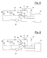
- test circuit of figure 4 in which two diodes are used in series (component indicated with 36) with a maximum inverse voltage of 8 kV and a maximum current equal to 0.4 A.
- a resistor 33 was also introduced, which limits the current to 0.4 A, whereas the condenser 32 is used to prevent a direct current from passing through the impulse generator 27 when it is switched off (the outlet of the generator 27, in fact, consists of an elevator transformer which would become overheated as a result of the direct voltage); finally, the condenser 22 protects the generator 20 from rapid overvoltages.
- the spark gap 11 consisting of two metallic electrodes at an adjustable distance, was used for the tests, and voltages and currents were measured with the oscilloscope 12, using the probe for high voltages 14, the current probe 13 and a differential probe 34.
- the high voltage probe 14 tolerates voltages up to 40 kV RMS and has a feed-through band of about 70 MHz, whereas the current probe 13 has a capacity up to 30 A and a feed-through band of 50 MHz; the differential probe 34 tolerates voltages up to 1.4 kV and has a band of about 10 MHz.
- the generator 20 when the generator 20 is switched on, the arc struck between the electrodes continues even after the impulsive voltage produced by the impulse generator 27 has become exhausted, as a result of the current supplied by the generator 20 through the diodes 36; as this current, however, is necessarily limited to 0.4 A, the phenomenon only lasts for a few tens of ⁇ s.
- this can be connected to the cathode 28 conductor (as illustrated in figure 3), so that, during the functioning of the pilot arc, the auxiliary anode 29 is at earth potential 31, or to that of the auxiliary anode 29, in which case the auxiliary anode 29 is brought to a potential of various kV, with respect to the earth potential 31; in this latter case, it is possible to use a diode 26 with a lower current capacity.
- the tests effected showed that the 50 ⁇ H inductor 35 does not yet represent an optimal filtration, as, although the current absorbed by the inductor 35 is low in percentage with respect to that supplied by the generator 20 during the discharge, the voltage drop inside the generator 20 with this current is still sufficient however to prevent the formation of the discharge.
- the inductor 35 still allows a current to pass which is such as to lower the voltage of the generator 20 before the discharge takes place; the problem could be solved by further increasing the inductance (by increasing the number of coils and the ferrite section), but it is believed that such an increase would not be easily compatible with the possibility of housing the striking circuit in the body of the plasma hand torch 25.
- the circuit of figure 6 ensures that the electrode forming the cathode 28 remains at the potential set by the generator 20 of the pilot arc (-250 V) until the discharge has been effectively initiated inside the second spark gap 36; at this point, in fact, the potential of the cathode 28 is brought within a very short time interval (in the order of a few ns) to an intermediate level between the voltage of the impulse generator 27 and the earth potential 31 (about 5 kV, in any case sufficient for effecting the discharge between the auxiliary cathode 28 and anode 29).
- the inductor with a ferrite nucleus 35 is then subjected to a voltage with a much shorter duration than that obtained with the circuit of figure 5 and this allows the striking circuit to be effectively separated from that of the generator 20, using a very small inductance; the period of time during which the inductor 35 must prevent the passage of current towards the generator 20 is in fact reduced by at least one 100 factor (from 5 ⁇ s to less than 50 ns).
- the inductor 35 consists of a series of high voltage insulated wire coils (Teflon insulation), wound around a toroidal ferrite nucleus having a diameter of about 25 mm.
- the duration of the discharge improves when the transformer of the traditional striking system, which was left, even in the absence of feeding, inside the generator 20, is short-circuited.
- the circuit illustrated in detail in the circuitry scheme of figure 7, where the same components as figure 6 have the same numerical references, uses an impulse generator 27 consisting of an ignition reel fed at 14 Volts in direct current and having an integrated circuit as oscillator.
- the signal generated is amplified by one or more transistors which apply it to the primary circuit of the reel, and high voltage impulses are obtained between the high voltage outlet of the reel and mass 31.
- the impulse generator thus conceived produces a voltage impulse with a frequency of about 100 Hz and the impulse has a rise and fall with frequencies in the order of 250 kHz.
- a further improvement of the circuit of figure 7 is represented by the circuitry scheme of figure 8, in which the components of figure 7 having the same function, are indicated with the same numerical references; in the circuitry scheme of figure 8, in particular, in addition to the use of the discharger 41 instead of the second spark gap 36, the inductor with a ferrite nucleus 37 is installed inverted, i.e. it is connected in series to the auxiliary anode 29, where a maximum current of 20 A passes, so as to have an inductance with a limited value.
Landscapes
- Physics & Mathematics (AREA)
- Engineering & Computer Science (AREA)
- Plasma & Fusion (AREA)
- Spectroscopy & Molecular Physics (AREA)
- Plasma Technology (AREA)
- Arc Welding Control (AREA)
- Generation Of Surge Voltage And Current (AREA)
Applications Claiming Priority (2)
| Application Number | Priority Date | Filing Date | Title |
|---|---|---|---|
| ITVI20030218 | 2003-11-05 | ||
| ITVI20030218 ITVI20030218A1 (it) | 2003-11-05 | 2003-11-05 | Circuito di innesco dell'arco pilota per torce ad arco plasma. |
Publications (3)
| Publication Number | Publication Date |
|---|---|
| EP1530409A2 true EP1530409A2 (de) | 2005-05-11 |
| EP1530409A3 EP1530409A3 (de) | 2006-08-09 |
| EP1530409B1 EP1530409B1 (de) | 2014-03-05 |
Family
ID=34430831
Family Applications (1)
| Application Number | Title | Priority Date | Filing Date |
|---|---|---|---|
| EP20040078075 Expired - Lifetime EP1530409B1 (de) | 2003-11-05 | 2004-11-05 | Zündschaltung des Pilotlichtbogens für Lichtbogen-Plasmabrenner |
Country Status (3)
| Country | Link |
|---|---|
| EP (1) | EP1530409B1 (de) |
| ES (1) | ES2461198T3 (de) |
| IT (1) | ITVI20030218A1 (de) |
Cited By (4)
| Publication number | Priority date | Publication date | Assignee | Title |
|---|---|---|---|---|
| RU2520374C1 (ru) * | 2013-02-20 | 2014-06-27 | Государственное Научное Учреждение "Институт Физики Имени Б.И. Степанова Национальной Академии Наук Беларуси" | Способ сокращения длительности импульса мощного свч излучения и устройство для его реализации |
| CN109982499A (zh) * | 2019-01-08 | 2019-07-05 | 上海硕余精密机械设备有限公司 | 一种等离子体电弧的引弧装置及方法 |
| CN114221569A (zh) * | 2021-12-21 | 2022-03-22 | 中国人民解放军国防科技大学 | 等离子体高能合成射流激励器并联放电装置及方法 |
| JP2023076493A (ja) * | 2021-10-07 | 2023-06-01 | ダイキン工業株式会社 | 放電装置、冷媒評価装置、及び冷媒評価方法 |
Families Citing this family (2)
| Publication number | Priority date | Publication date | Assignee | Title |
|---|---|---|---|---|
| CZ305206B6 (cs) * | 2010-12-31 | 2015-06-10 | Ústav Fyziky Plazmatu Akademie Věd České Republiky, V. V. I. | Plazmatron s obloukem stabilizovaným kapalinou |
| CN115856397B (zh) * | 2022-12-09 | 2023-08-25 | 哈尔滨工程大学 | 一种等离子点火系统的放电电压测量辅助工具 |
Family Cites Families (3)
| Publication number | Priority date | Publication date | Assignee | Title |
|---|---|---|---|---|
| US4225769A (en) * | 1977-09-26 | 1980-09-30 | Thermal Dynamics Corporation | Plasma torch starting circuit |
| US5170030A (en) * | 1991-04-08 | 1992-12-08 | Thermal Dynamics Corporation | Plasma torch electronic pulsing circuit |
| US5235162A (en) * | 1992-05-26 | 1993-08-10 | Tescom Corporation | Plasma pilot arc ignition system |
-
2003
- 2003-11-05 IT ITVI20030218 patent/ITVI20030218A1/it unknown
-
2004
- 2004-11-05 ES ES04078075T patent/ES2461198T3/es not_active Expired - Lifetime
- 2004-11-05 EP EP20040078075 patent/EP1530409B1/de not_active Expired - Lifetime
Cited By (6)
| Publication number | Priority date | Publication date | Assignee | Title |
|---|---|---|---|---|
| RU2520374C1 (ru) * | 2013-02-20 | 2014-06-27 | Государственное Научное Учреждение "Институт Физики Имени Б.И. Степанова Национальной Академии Наук Беларуси" | Способ сокращения длительности импульса мощного свч излучения и устройство для его реализации |
| CN109982499A (zh) * | 2019-01-08 | 2019-07-05 | 上海硕余精密机械设备有限公司 | 一种等离子体电弧的引弧装置及方法 |
| CN109982499B (zh) * | 2019-01-08 | 2022-10-21 | 上海硕余精密机械设备有限公司 | 一种等离子体电弧的引弧装置及方法 |
| JP2023076493A (ja) * | 2021-10-07 | 2023-06-01 | ダイキン工業株式会社 | 放電装置、冷媒評価装置、及び冷媒評価方法 |
| CN114221569A (zh) * | 2021-12-21 | 2022-03-22 | 中国人民解放军国防科技大学 | 等离子体高能合成射流激励器并联放电装置及方法 |
| CN114221569B (zh) * | 2021-12-21 | 2023-12-01 | 中国人民解放军国防科技大学 | 等离子体高能合成射流激励器并联放电装置及方法 |
Also Published As
| Publication number | Publication date |
|---|---|
| EP1530409A3 (de) | 2006-08-09 |
| EP1530409B1 (de) | 2014-03-05 |
| ES2461198T3 (es) | 2014-05-19 |
| ITVI20030218A1 (it) | 2005-05-06 |
Similar Documents
| Publication | Publication Date | Title |
|---|---|---|
| CN102202455B (zh) | 等离子体生成设备 | |
| CN104735894A (zh) | 等离子体点火装置,等离子体点火方法及等离子体发生装置 | |
| JPH11191475A (ja) | 稲妻保護を含む通信システム | |
| EP1530409B1 (de) | Zündschaltung des Pilotlichtbogens für Lichtbogen-Plasmabrenner | |
| US7295416B2 (en) | Device and method for triggering a spark gap | |
| EP2378845A2 (de) | Plasmaerzeugungsvorrichtung | |
| US2456986A (en) | Protective arrangement for electrical windings | |
| JP6882031B2 (ja) | イオン測定及びacリンギング抑制を行う容量性点火装置 | |
| US2108465A (en) | Surge arrester | |
| US8861174B2 (en) | Device and method for quick closing of an electric circuit and a use of the device | |
| KR20220133855A (ko) | 마이크로파 신호로부터 고레벨 전자파 방해를 분리하는 방법 및 디바이스 | |
| Moran et al. | Voltage recovery time of small spark gaps | |
| US3254268A (en) | Protective system for capacitance serially connected with inductive apparatus | |
| US3474290A (en) | Ignition circuit for an arc-discharge lamp and devices therefor | |
| EP1355393B1 (de) | Vorrichtung zum Schutz eines Objektes vor Blitzeinschlag | |
| JP4385105B2 (ja) | 放電点弧装置 | |
| Wheatcroft et al. | I. The transition from glow to arc discharge | |
| Arkhipov et al. | Transients during stationary plasma thruster start-up | |
| Burtsev et al. | Investigation of a 100-kV linear gas-filled discharger with a distorted electric field | |
| JPH0584578A (ja) | プラズマ装置 | |
| Hall | A study of radio interference from the electric ignition of internal combustion motors | |
| Whitlow | A 450J spark discharge for shadowgraph photography | |
| JPH02304888A (ja) | ボールギャップ・アレスタ | |
| van Herel et al. | Wire Explosion by Electromagnetic Induction | |
| JPH03252074A (ja) | 電気機器の切り離し装置 |
Legal Events
| Date | Code | Title | Description |
|---|---|---|---|
| PUAI | Public reference made under article 153(3) epc to a published international application that has entered the european phase |
Free format text: ORIGINAL CODE: 0009012 |
|
| AK | Designated contracting states |
Kind code of ref document: A2 Designated state(s): AT BE BG CH CY CZ DE DK EE ES FI FR GB GR HU IE IS IT LI LU MC NL PL PT RO SE SI SK TR |
|
| AX | Request for extension of the european patent |
Extension state: AL HR LT LV MK YU |
|
| PUAL | Search report despatched |
Free format text: ORIGINAL CODE: 0009013 |
|
| AK | Designated contracting states |
Kind code of ref document: A3 Designated state(s): AT BE BG CH CY CZ DE DK EE ES FI FR GB GR HU IE IS IT LI LU MC NL PL PT RO SE SI SK TR |
|
| AX | Request for extension of the european patent |
Extension state: AL HR LT LV MK YU |
|
| 17P | Request for examination filed |
Effective date: 20061025 |
|
| AKX | Designation fees paid |
Designated state(s): AT BE BG CH CY CZ DE DK EE ES FI FR GB GR HU IE IS IT LI LU MC NL PL PT RO SE SI SK TR |
|
| 17Q | First examination report despatched |
Effective date: 20080710 |
|
| GRAP | Despatch of communication of intention to grant a patent |
Free format text: ORIGINAL CODE: EPIDOSNIGR1 |
|
| INTG | Intention to grant announced |
Effective date: 20130805 |
|
| GRAS | Grant fee paid |
Free format text: ORIGINAL CODE: EPIDOSNIGR3 |
|
| GRAA | (expected) grant |
Free format text: ORIGINAL CODE: 0009210 |
|
| RAP1 | Party data changed (applicant data changed or rights of an application transferred) |
Owner name: MERGERT S.P.A. |
|
| AK | Designated contracting states |
Kind code of ref document: B1 Designated state(s): AT BE BG CH CY CZ DE DK EE ES FI FR GB GR HU IE IS IT LI LU MC NL PL PT RO SE SI SK TR |
|
| RAP1 | Party data changed (applicant data changed or rights of an application transferred) |
Owner name: TRAFIMET S.P.A. |
|
| REG | Reference to a national code |
Ref country code: GB Ref legal event code: FG4D |
|
| REG | Reference to a national code |
Ref country code: CH Ref legal event code: EP |
|
| REG | Reference to a national code |
Ref country code: AT Ref legal event code: REF Ref document number: 655600 Country of ref document: AT Kind code of ref document: T Effective date: 20140315 |
|
| REG | Reference to a national code |
Ref country code: IE Ref legal event code: FG4D |
|
| REG | Reference to a national code |
Ref country code: DE Ref legal event code: R096 Ref document number: 602004044505 Country of ref document: DE Effective date: 20140417 |
|
| REG | Reference to a national code |
Ref country code: ES Ref legal event code: FG2A Ref document number: 2461198 Country of ref document: ES Kind code of ref document: T3 Effective date: 20140519 |
|
| REG | Reference to a national code |
Ref country code: NL Ref legal event code: VDEP Effective date: 20140305 |
|
| PG25 | Lapsed in a contracting state [announced via postgrant information from national office to epo] |
Ref country code: CY Free format text: LAPSE BECAUSE OF FAILURE TO SUBMIT A TRANSLATION OF THE DESCRIPTION OR TO PAY THE FEE WITHIN THE PRESCRIBED TIME-LIMIT Effective date: 20140305 Ref country code: SE Free format text: LAPSE BECAUSE OF FAILURE TO SUBMIT A TRANSLATION OF THE DESCRIPTION OR TO PAY THE FEE WITHIN THE PRESCRIBED TIME-LIMIT Effective date: 20140305 |
|
| PG25 | Lapsed in a contracting state [announced via postgrant information from national office to epo] |
Ref country code: BG Free format text: LAPSE BECAUSE OF FAILURE TO SUBMIT A TRANSLATION OF THE DESCRIPTION OR TO PAY THE FEE WITHIN THE PRESCRIBED TIME-LIMIT Effective date: 20140605 Ref country code: BE Free format text: LAPSE BECAUSE OF FAILURE TO SUBMIT A TRANSLATION OF THE DESCRIPTION OR TO PAY THE FEE WITHIN THE PRESCRIBED TIME-LIMIT Effective date: 20140305 Ref country code: IS Free format text: LAPSE BECAUSE OF FAILURE TO SUBMIT A TRANSLATION OF THE DESCRIPTION OR TO PAY THE FEE WITHIN THE PRESCRIBED TIME-LIMIT Effective date: 20140705 Ref country code: RO Free format text: LAPSE BECAUSE OF FAILURE TO SUBMIT A TRANSLATION OF THE DESCRIPTION OR TO PAY THE FEE WITHIN THE PRESCRIBED TIME-LIMIT Effective date: 20140305 Ref country code: EE Free format text: LAPSE BECAUSE OF FAILURE TO SUBMIT A TRANSLATION OF THE DESCRIPTION OR TO PAY THE FEE WITHIN THE PRESCRIBED TIME-LIMIT Effective date: 20140305 Ref country code: NL Free format text: LAPSE BECAUSE OF FAILURE TO SUBMIT A TRANSLATION OF THE DESCRIPTION OR TO PAY THE FEE WITHIN THE PRESCRIBED TIME-LIMIT Effective date: 20140305 Ref country code: CZ Free format text: LAPSE BECAUSE OF FAILURE TO SUBMIT A TRANSLATION OF THE DESCRIPTION OR TO PAY THE FEE WITHIN THE PRESCRIBED TIME-LIMIT Effective date: 20140305 |
|
| PG25 | Lapsed in a contracting state [announced via postgrant information from national office to epo] |
Ref country code: PL Free format text: LAPSE BECAUSE OF FAILURE TO SUBMIT A TRANSLATION OF THE DESCRIPTION OR TO PAY THE FEE WITHIN THE PRESCRIBED TIME-LIMIT Effective date: 20140305 Ref country code: SK Free format text: LAPSE BECAUSE OF FAILURE TO SUBMIT A TRANSLATION OF THE DESCRIPTION OR TO PAY THE FEE WITHIN THE PRESCRIBED TIME-LIMIT Effective date: 20140305 |
|
| REG | Reference to a national code |
Ref country code: DE Ref legal event code: R097 Ref document number: 602004044505 Country of ref document: DE |
|
| PG25 | Lapsed in a contracting state [announced via postgrant information from national office to epo] |
Ref country code: PT Free format text: LAPSE BECAUSE OF FAILURE TO SUBMIT A TRANSLATION OF THE DESCRIPTION OR TO PAY THE FEE WITHIN THE PRESCRIBED TIME-LIMIT Effective date: 20140707 |
|
| PLBE | No opposition filed within time limit |
Free format text: ORIGINAL CODE: 0009261 |
|
| STAA | Information on the status of an ep patent application or granted ep patent |
Free format text: STATUS: NO OPPOSITION FILED WITHIN TIME LIMIT |
|
| PG25 | Lapsed in a contracting state [announced via postgrant information from national office to epo] |
Ref country code: DK Free format text: LAPSE BECAUSE OF FAILURE TO SUBMIT A TRANSLATION OF THE DESCRIPTION OR TO PAY THE FEE WITHIN THE PRESCRIBED TIME-LIMIT Effective date: 20140305 |
|
| 26N | No opposition filed |
Effective date: 20141208 |
|
| REG | Reference to a national code |
Ref country code: DE Ref legal event code: R097 Ref document number: 602004044505 Country of ref document: DE Effective date: 20141208 |
|
| PG25 | Lapsed in a contracting state [announced via postgrant information from national office to epo] |
Ref country code: SI Free format text: LAPSE BECAUSE OF FAILURE TO SUBMIT A TRANSLATION OF THE DESCRIPTION OR TO PAY THE FEE WITHIN THE PRESCRIBED TIME-LIMIT Effective date: 20140305 |
|
| PG25 | Lapsed in a contracting state [announced via postgrant information from national office to epo] |
Ref country code: MC Free format text: LAPSE BECAUSE OF FAILURE TO SUBMIT A TRANSLATION OF THE DESCRIPTION OR TO PAY THE FEE WITHIN THE PRESCRIBED TIME-LIMIT Effective date: 20140305 Ref country code: LU Free format text: LAPSE BECAUSE OF FAILURE TO SUBMIT A TRANSLATION OF THE DESCRIPTION OR TO PAY THE FEE WITHIN THE PRESCRIBED TIME-LIMIT Effective date: 20141105 |
|
| REG | Reference to a national code |
Ref country code: CH Ref legal event code: PL |
|
| GBPC | Gb: european patent ceased through non-payment of renewal fee |
Effective date: 20141105 |
|
| PG25 | Lapsed in a contracting state [announced via postgrant information from national office to epo] |
Ref country code: CH Free format text: LAPSE BECAUSE OF NON-PAYMENT OF DUE FEES Effective date: 20141130 Ref country code: LI Free format text: LAPSE BECAUSE OF NON-PAYMENT OF DUE FEES Effective date: 20141130 |
|
| REG | Reference to a national code |
Ref country code: IE Ref legal event code: MM4A |
|
| PG25 | Lapsed in a contracting state [announced via postgrant information from national office to epo] |
Ref country code: IE Free format text: LAPSE BECAUSE OF NON-PAYMENT OF DUE FEES Effective date: 20141105 Ref country code: GB Free format text: LAPSE BECAUSE OF NON-PAYMENT OF DUE FEES Effective date: 20141105 |
|
| REG | Reference to a national code |
Ref country code: FR Ref legal event code: PLFP Year of fee payment: 12 |
|
| PG25 | Lapsed in a contracting state [announced via postgrant information from national office to epo] |
Ref country code: GR Free format text: LAPSE BECAUSE OF FAILURE TO SUBMIT A TRANSLATION OF THE DESCRIPTION OR TO PAY THE FEE WITHIN THE PRESCRIBED TIME-LIMIT Effective date: 20140606 |
|
| PG25 | Lapsed in a contracting state [announced via postgrant information from national office to epo] |
Ref country code: HU Free format text: LAPSE BECAUSE OF FAILURE TO SUBMIT A TRANSLATION OF THE DESCRIPTION OR TO PAY THE FEE WITHIN THE PRESCRIBED TIME-LIMIT; INVALID AB INITIO Effective date: 20041105 Ref country code: TR Free format text: LAPSE BECAUSE OF FAILURE TO SUBMIT A TRANSLATION OF THE DESCRIPTION OR TO PAY THE FEE WITHIN THE PRESCRIBED TIME-LIMIT Effective date: 20140305 |
|
| REG | Reference to a national code |
Ref country code: FR Ref legal event code: PLFP Year of fee payment: 13 |
|
| REG | Reference to a national code |
Ref country code: FR Ref legal event code: PLFP Year of fee payment: 14 |
|
| REG | Reference to a national code |
Ref country code: FR Ref legal event code: PLFP Year of fee payment: 15 |
|
| PGFP | Annual fee paid to national office [announced via postgrant information from national office to epo] |
Ref country code: FI Payment date: 20201109 Year of fee payment: 17 |
|
| PGFP | Annual fee paid to national office [announced via postgrant information from national office to epo] |
Ref country code: ES Payment date: 20211206 Year of fee payment: 18 Ref country code: AT Payment date: 20211025 Year of fee payment: 18 Ref country code: DE Payment date: 20211027 Year of fee payment: 18 |
|
| PGFP | Annual fee paid to national office [announced via postgrant information from national office to epo] |
Ref country code: IT Payment date: 20211018 Year of fee payment: 18 Ref country code: FR Payment date: 20211029 Year of fee payment: 18 |
|
| REG | Reference to a national code |
Ref country code: FI Ref legal event code: MAE |
|
| PG25 | Lapsed in a contracting state [announced via postgrant information from national office to epo] |
Ref country code: FI Free format text: LAPSE BECAUSE OF NON-PAYMENT OF DUE FEES Effective date: 20211105 |
|
| REG | Reference to a national code |
Ref country code: DE Ref legal event code: R119 Ref document number: 602004044505 Country of ref document: DE |
|
| P01 | Opt-out of the competence of the unified patent court (upc) registered |
Effective date: 20230518 |
|
| REG | Reference to a national code |
Ref country code: AT Ref legal event code: MM01 Ref document number: 655600 Country of ref document: AT Kind code of ref document: T Effective date: 20221105 |
|
| PG25 | Lapsed in a contracting state [announced via postgrant information from national office to epo] |
Ref country code: AT Free format text: LAPSE BECAUSE OF NON-PAYMENT OF DUE FEES Effective date: 20221105 |
|
| PG25 | Lapsed in a contracting state [announced via postgrant information from national office to epo] |
Ref country code: IT Free format text: LAPSE BECAUSE OF NON-PAYMENT OF DUE FEES Effective date: 20221105 Ref country code: DE Free format text: LAPSE BECAUSE OF NON-PAYMENT OF DUE FEES Effective date: 20230601 |
|
| PG25 | Lapsed in a contracting state [announced via postgrant information from national office to epo] |
Ref country code: FR Free format text: LAPSE BECAUSE OF NON-PAYMENT OF DUE FEES Effective date: 20221130 |
|
| REG | Reference to a national code |
Ref country code: ES Ref legal event code: FD2A Effective date: 20231227 |
|
| PG25 | Lapsed in a contracting state [announced via postgrant information from national office to epo] |
Ref country code: ES Free format text: LAPSE BECAUSE OF NON-PAYMENT OF DUE FEES Effective date: 20221106 |
|
| PG25 | Lapsed in a contracting state [announced via postgrant information from national office to epo] |
Ref country code: ES Free format text: LAPSE BECAUSE OF NON-PAYMENT OF DUE FEES Effective date: 20221106 |