EP1530899B1 - Beschränkung der Wanderung von Tieren, z.B. auf einem Bauplatz - Google Patents
Beschränkung der Wanderung von Tieren, z.B. auf einem Bauplatz Download PDFInfo
- Publication number
- EP1530899B1 EP1530899B1 EP04256940A EP04256940A EP1530899B1 EP 1530899 B1 EP1530899 B1 EP 1530899B1 EP 04256940 A EP04256940 A EP 04256940A EP 04256940 A EP04256940 A EP 04256940A EP 1530899 B1 EP1530899 B1 EP 1530899B1
- Authority
- EP
- European Patent Office
- Prior art keywords
- panel
- ground
- trench
- panels
- tines
- Prior art date
- Legal status (The legal status is an assumption and is not a legal conclusion. Google has not performed a legal analysis and makes no representation as to the accuracy of the status listed.)
- Expired - Lifetime
Links
- 241001465754 Metazoa Species 0.000 title claims abstract description 27
- 230000005012 migration Effects 0.000 title claims abstract description 7
- 238000013508 migration Methods 0.000 title claims abstract description 7
- 238000000034 method Methods 0.000 claims abstract description 30
- OCDRLZFZBHZTKQ-NMUBGGKPSA-N onetine Chemical compound C[C@@H](O)[C@@]1(O)C[C@@H](C)[C@@](C)(O)C(=O)OC\C2=C\CN(C)CC[C@@H](OC1=O)C2=O OCDRLZFZBHZTKQ-NMUBGGKPSA-N 0.000 claims description 2
- 230000004888 barrier function Effects 0.000 abstract description 55
- -1 polyethylene Polymers 0.000 description 15
- 239000004698 Polyethylene Substances 0.000 description 9
- 238000010276 construction Methods 0.000 description 9
- 229920000573 polyethylene Polymers 0.000 description 9
- 239000000463 material Substances 0.000 description 7
- 239000004743 Polypropylene Substances 0.000 description 6
- 229920001155 polypropylene Polymers 0.000 description 6
- 230000004048 modification Effects 0.000 description 5
- 238000012986 modification Methods 0.000 description 5
- XEEYBQQBJWHFJM-UHFFFAOYSA-N Iron Chemical compound [Fe] XEEYBQQBJWHFJM-UHFFFAOYSA-N 0.000 description 4
- 238000005728 strengthening Methods 0.000 description 4
- 230000000694 effects Effects 0.000 description 3
- 241000270322 Lepidosauria Species 0.000 description 2
- 229910000831 Steel Inorganic materials 0.000 description 2
- 230000000254 damaging effect Effects 0.000 description 2
- 229910052742 iron Inorganic materials 0.000 description 2
- 239000010959 steel Substances 0.000 description 2
- 241000269350 Anura Species 0.000 description 1
- 241000393427 Cepaea hortensis Species 0.000 description 1
- 241001416537 Gliridae Species 0.000 description 1
- 241000124008 Mammalia Species 0.000 description 1
- 241000157049 Microtus richardsoni Species 0.000 description 1
- 241000270295 Serpentes Species 0.000 description 1
- 230000009471 action Effects 0.000 description 1
- 239000000853 adhesive Substances 0.000 description 1
- 230000001070 adhesive effect Effects 0.000 description 1
- 230000008901 benefit Effects 0.000 description 1
- 230000015572 biosynthetic process Effects 0.000 description 1
- 230000009194 climbing Effects 0.000 description 1
- 238000011161 development Methods 0.000 description 1
- 230000018109 developmental process Effects 0.000 description 1
- 238000005755 formation reaction Methods 0.000 description 1
- 230000005923 long-lasting effect Effects 0.000 description 1
- 239000004033 plastic Substances 0.000 description 1
- 229920003023 plastic Polymers 0.000 description 1
- 231100000614 poison Toxicity 0.000 description 1
- 241000894007 species Species 0.000 description 1
- 239000003440 toxic substance Substances 0.000 description 1
- 238000003466 welding Methods 0.000 description 1
Images

Classifications
-
- A—HUMAN NECESSITIES
- A01—AGRICULTURE; FORESTRY; ANIMAL HUSBANDRY; HUNTING; TRAPPING; FISHING
- A01M—CATCHING, TRAPPING OR SCARING OF ANIMALS; APPARATUS FOR THE DESTRUCTION OF NOXIOUS ANIMALS OR NOXIOUS PLANTS
- A01M29/00—Scaring or repelling devices, e.g. bird-scaring apparatus
- A01M29/30—Scaring or repelling devices, e.g. bird-scaring apparatus preventing or obstructing access or passage, e.g. by means of barriers, spikes, cords, obstacles or sprinkled water
Definitions
- This invention relates to (i) a method of restricting migration of animals, (ii) a barrier for that purpose, and (iii) a kit for use in performing such a method or for constructing such a barrier.
- a trench is cut in the ground to a depth of about 0.3 m (1 ft) and wooden stakes are driven into the ground in, or immediately to the side of, the trench so that they project upwards by at least about 0.6m (2 ft) above the bottom of the trench.
- Flexible polyethylene sheet is then taken from a roll and attached, by battens and nails or staples, to the sides of the stakes so that the polyethylene sheet extends from stake to stake and from the top of each stake to the bottom of the trench.
- the trench can then be backfilled if desired.
- the resultant barrier extends to a sufficient height above the ground that many such small animals will not attempt to, or be able to, climb or jump over it, and it extends to a sufficient depth below the ground that most such small animals will not attempt to, or be able to, burrow under it.
- the known temporary barrier has proved not to be particularly environmentally friendly. Especially if the polyethylene sheet is folded at the bottom of the trench, it can be difficult to remove from the ground and so sometimes at least the buried part of the sheet is left in the ground, therefore leaving a barrier below ground to the animals which is at least semi-permanent even if biodegradable polyethylene is used. In any case, after use, the polyethylene sheet is often not in a fit state to be used again and is disposed of, which is wasteful of resources. In an attempt not to be wasteful of resources and to facilitate driving of them into the ground, stakes are used of small cross-section, e.g.
- the present invention is concerned with overcoming at least to some extent some of the problems mentioned above.
- a method of restricting migration of animals from the ground on one side of a line to the ground on the other side of the line comprising the steps of: cutting a trench in the ground along the line; setting a rigid or semi-rigid panel in the trench so that the panel projects upwards above the level of the ground; providing a staple having a pair of elongate tines connected by a bridging portion so that the tines extend downwardly, from the bridging portion, on either side of the panel to locate the panel therebetween; and driving the staple into the ground, after the panel has been set in the ground, so that the tines restrict sideways movement of the panel and the bridging portion restricts upward movement of the panel.
- a panel that is rigid or semi-rigid, it does not need to be held in tension, and for that reason it does not need to be positively attached to the members with nails, staples or the like. Also, because the panel is located between the tines to restrict sideways movement of the panel, for that reason also it does not need to be positively attached to the members with nails, staples or the like. Because the panel is rigid or semi-rigid, it can be more readily fabricated so that it can be drawn out of the ground once it is no longer required. Because of the use of a staple, the tines to either side of the panel can both be driven into the ground by a single driving action.
- the tines of the staple may be of generally equal length, or one may be longer than the other so that only one of the tines is driven into the ground to any significant extent. Furthermore, the bridging portion of the staple serves to restrict upward movement of the panel. Although the method was conceived for use in the temporary restriction of the migration of small animals, it can also be used to form a permanent or semi-permanent barrier.
- patent document DE-U-8604767 describes a garden snail barrier in which an upstanding rigid panel on the ground is held between pairs of posts.
- the method preferably further includes the step of setting another panel in the trench next to the first mentioned panel so that adjacent ends of the panels overlap.
- a barrier of any desired length can be constructed.
- account can be taken of any undulation in the ground level.
- the staples may be disposed at the overlaps so that one tine engages one of the panels and the other tine engages the other panel.
- the spacing between the tines is preferably substantially greater than the thickness of the panel or the overlapping panels, and the direction of spacing of the tines is preferably inclined relative to the thickness direction of the panel or panels so that the panel or panels are closely sandwiched between the tines.
- the method may further include the steps of: setting another panel in the trench next to and spaced from the first mentioned panel; and setting a pitfall trap in the ground so that the first panel and the further panel both abut a side wall of the pitfall trap.
- the side wall of the trap is preferably polygonally-cylindrical (for example rectangularly-, pentagonally-, hexagonally-, heptagonally- or octagonally-cylindrical) and each panel abuts face-to-face against a respective portion of the side wall of the trap. This assists in maintaining the integrity of the barrier.
- the, or each, panel is substantially flat.
- the panel has a main portion which is substantially flat, and a lip which extends along one edge of the main portion so that the panel is generally L-shaped in cross-section.
- the trench that is cut is at least as wide as the width of the lip
- the panel is set into the trench with its lip lowermost
- the method further includes the step of backfilling the trench above the lip.
- the lip is arranged so that it projects from the main portion of the panel in the direction away from the worksite. The lip provides a deterrent to small animals burrowing under the panel into the worksite.
- the length of the shorter tine is preferably less than the height of the main portion of the panel so that the shorter tine does not pierce the lip.
- the length of the longer tine is preferably greater than the height of the main portion of the panel.
- a strip of biodegradable flexible material may be releasably attached along one edge thereof to one edge of the panel; in this case, the panel is set into the trench with said one edge lowermost, the strip is set in the trench so that it extends across the bottom of the trench, and the method further includes the step of backfilling the trench above the lip.
- the strip detaches itself from the panel and remains buried in the ground where, in time, it biodegrades.
- the, or each, panel is formed of plastics material (such as polypropylene), having at least one face that is smooth. This makes it difficult for many small animals to scale that face of the panel.
- the other face of the panel may be non-smooth so as to facilitate scaling of that face of the panel.
- kits for use in performing the method of the first aspect of the invention comprising a plurality of such panels, a plurality of such staples, a machine for cutting the trench and a hammer or the like for driving the staples into the ground.
- the kit may also include at least one container having a polygonally-cylindrical side wall, for forming a pitfall trap.
- a barrier 10 (which does not form an embodiment of the invention) is constructed in and above a piece of ground 12.
- the barrier comprises a series of rectangular panels 14 of polypropylene.
- the faces of the panels 14 are smooth.
- Each panel 14 may typically have a thickness T of 3 mm to 6 mm (1 ⁇ 8" to 1 ⁇ 4"), a length L of about 2.4 m (8 ft) and a height H of about 0.6 m (2 ft), and the panels 14 may conveniently be formed by cutting a 2.4 m x 1.2 m (8 by 4) sheet of polypropylene in half.
- the panels 14 may have other dimensions as required.
- the panels 14 are set in the ground 12 to about half their height (i.e.
- a series of steel or iron road pins 18 are implanted in the ground 12 alternately to one side and to the other side of the series of panels 14.
- the shafts 20 of the road pins 18 restrain sideways movement of the panels 14 in the ground 12, and the hooks 22 at the tops of the road pins 18 are arranged to restrain upwards movement of the panels 14 out of the ground 12.
- undulation in the ground level can be taken into account by uneven overlap 16 of the adjacent ends of the panels 14.
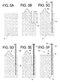
- Figure 5A shows the unprepared piece of ground 12.
- a trench 24 is cut in the ground 12 to a depth D of about 0.3 m (1 ft) and of any convenient width W greater than twice the thickness T of the panels, as shown in Figure 5B .
- the trench may be cut in any of a variety of different ways, for example using a single-bladed plough or a mini-digger with a 0.15 m (6") or 0.3 m (1 ft) wide bucket, but preferably using a trenching wheel so that the trench 24 has clean vertical or near-vertical sides.
- a series of the road pins 18a are then driven into the ground 12, using a hammer or other suitable tool, immediately to one side of the trench 24 and with their hooks 22 overhanging the trench 24, as shown in Figure 5C , so that the distance between the foot of the trench 24 and the underside of the hooks 22 of the road pins is slightly greater than the height H of the polypropylene panels 14.
- the spacing between adjacent road pins 18a is not greater than the length L of the polypropylene panels 14 less the desired amount of overlap 16 of adjacent panels 14.
- the panels 14 are then set in the trench 24 facing against the pins 18a, as shown in Figure 5D , and with the desired amount of overlap 16 of adjacent panels 14.
- a second series of the road pins 18b are then driven into the ground 12, against the opposite faces of the panels 14 and with their hooks 22 overhanging the panels 14, as shown in Figure 5E .
- the trench 24 is then backfilled with the material that was initially removed from it, as shown in Figure 5F .
- the panels 14 are buried to about half of their height in the ground 12.
- the shafts 20 of the pins 18 on alternate sides of the panels 14 restrict sideways flexing of the panels 14 above ground level.
- the hooks 22 of the pins restrict upwards movement of the panels 14 out of the ground 12. Small animals cannot pass from one side of the barrier 10 to the other unless they can scale the smooth sides of, or jump over, the panels 14 reaching a height of about 0.3 m (1 ft) above ground level, or unless they can burrow into the ground 12 to a depth of at least about 0.3 m (1 ft) under the panels 14.
- barrier 10 Once the barrier 10 has been constructed around a worksite, as many small animals as possible that are within the barrier 10 are manually collected and evacuated to the other side of the barrier 10. To assist collection, sheets of old carpet, roofing felt or corrugated "tin" may be laid on the ground, encouraging the animals to congregate under the sheets. After a time, the sheets are lifted, and the animals are collected up and evacuated.
- the barrier 10 may be removed, simply by pulling the pins 18 out of the ground, and then by drawing the panels 14 out of the ground.
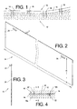
- the sheets 14 may be provided with hand-holes 26, as shown in Figure 2 , adjacent their upper edges.
- each staple 28 has a pair of parallel tines 30 integrally formed with a bridging portion 32 connecting the upper ends of the tines 30.
- the tines 30 are also connected adjacent their upper ends by a strengthening strip 34.
- the spacing between the tines 30 may, for example, be about 75 mm (3").
- a staple 28 is driven into the ground 12, with the bridging portion 32 inclined relative to the longitudinal direction of the panels 14 as shown in Figure 8 , so that the faces of the panels 14 at the overlap 16 are closely sandwiched between the tines, as shown in Figure 7 .
- the staple 28 is not driven into the ground 12 so far that the strengthening strip 34 touches the upper edge(s) of the panel(s) 14 so as to avoid damaging the panel(s) 14.
- a hook on a ratchet jack or on the arm of mini-digger can conveniently be inserted into the space between the bridging portion 32 and the strengthening strip 34 of the staple 28.
- the panel 14 of the second embodiment is L-shaped in cross-section, having a main portion 36, similar to the panel 14 of the first embodiment, and a lip 38 having a width W1 of about 0.2 to 0.3 m (8" to 12").
- the panel 14 may be formed by heat-folding a flat sheet of polypropylene, or by welding the main portion 36 and the lip 38 together.
- the staple 28 of Figure 10 is similar to the staple 28 of Figure 6 except that one of its tines 30a is substantially shorter than the other tine 30b, extending downwards from the strengthening strip 34 by a distance less than the height H of the main portion 36 of the panel 14.
- the width W of the trench 24 that is cut is greater than the width W1 of the lip 38 of the panel 14, as shown in Figure 11A .
- a pair of panels 14 are set in the trench 24 with their lips 38 extending from their main portions 36 in the direction away from the worksite and with the ends of their main portions 36 and lips 38 overlapping.
- the longer tine 30b of the staple 28 is then driven into the ground 12 on the opposite side of the main portions 36 to the lips 38, as shown in Figure 11A , and then the trench is backfilled, as shown in Figure 11B .
- the effect of the lip 38 of the barrier of the second embodiment is that, if a small animal burrows underground at a depth less than about 0.3m (1 ft) towards the worksite, it will reach the main portion 36 of the barrier. If it then burrows downwards in an attempt to burrow under the barrier, it will then reach the lip 38, which will have the effect of preventing further downward burrowing, and will lead the animal to re-trace its steps, to burrow sideways above the lip 38 or to begin burrowing in the direction away from the worksite.
- the lip 38 provides this benefit, it should be noted that the lip 38 will make subsequent removal of the panel 14 more difficult than in the case of the first and second embodiments, and that some excavating of the ground may be required in order to release the panel 14 from the ground. In order to overcome this disadvantage, the lip 38 may be formed from a flexible material to facilitate drawing of the panel 14 out of the ground.
- the main portion 36 of the barrier and the lip 38 may be formed from a single panel in which a groove is routed so as to facilitate creasing of the panel so as to form the main portion 36 and the lip 38.
- the panel may be of "twin wall" construction with ribs extending in the longitudinal direction of the barrier so that the panel can be creased between an adjacent pair of ribs so as to form the main portion 36 and the lip 38.
- a lip may be formed at the top of the main portion 36 of the barrier inclined at an angle of, for example, 45 degrees to the main portion 36 away from the worksite. Such a lip can make it even more difficult for a small animal to scale the barrier.
- Two or more holes are formed in the upper lip adjacent the main portion through which the shorter tines 30a of the staples 28 pass.
- the third embodiment of the invention will now be described with reference to Figures 12 to 14 .
- the third embodiment and its method of construction are similar to the second embodiment of Figures 9 to 11B except in the following respects.
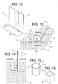
- the panel 14 of Figures 12 to 14 is formed of a rigid or semi-rigid main portion 36 similar to the panel 14 of Figures 1 to 8 , but having a strip 40 of thin flexible biodegradable material releasably attached along one edge of the strip 40 to the lower edge of the main portion 36 of the panel 14.
- the main portion 36 and the strip 40 may be releasably attached in any convenient way, for example by a weak weld, by a weak adhesive, or by clips.
- the strip 40 of the barrier 10 of Figures 12 to 14 has a similar effect to the lip 38 of the barrier 10 of Figures 9 to 11B .
- the main portion 36 is simply withdrawn from the ground 12 (after the staples 28 have been removed), and the intention is that the main portion 36 separates from the strip 40, leaving the strip 40 in the ground 12. Because the strip 40 is buried substantially horizontally in the ground 12, it does not provide any significant impediment to burrowing animals. Also, because the strip 40 is of biodegradable material, it does not have any long-lasting damaging effects.
- Figures 13 and 14 show a turn in the barrier 10 through an angle of about 60°.
- a pitfall trap 42 is set in the ground 12 at the turn.
- the pitfall trap 42 is in the form of container having a cylindrical side wall 44, a closed bottom 46 and an open top. Rather than being circularly-cylindrical as is conventional, the side wall 44 of the trap 42 is hexagonally-cylindrical, and the trap 42 is set in the ground 12 so that panels 14 of the two portions of the barrier 10 to either side of the trap overlap with and are generally in face-to-face contact with the two of the sides of the side wall 44.
- both faces of the panels 14 may be smooth and the other face may have surface formations such as a chequered pattern.
- the panels 14 are arranged so that the non-smooth face faces the worksite and the smooth face faces the environs.
- the non-smooth surface may facilitate climbing animals to scale the barrier to escape from the worksite to the environs, and yet the smooth surface makes it difficult or impossible for them to scale the barrier so as to enter the worksite from the environs.
Landscapes
- Life Sciences & Earth Sciences (AREA)
- Birds (AREA)
- Engineering & Computer Science (AREA)
- Insects & Arthropods (AREA)
- Pest Control & Pesticides (AREA)
- Wood Science & Technology (AREA)
- Zoology (AREA)
- Environmental Sciences (AREA)
- Catching Or Destruction (AREA)
- Medicines Containing Material From Animals Or Micro-Organisms (AREA)
- Pharmaceuticals Containing Other Organic And Inorganic Compounds (AREA)
- Medicines That Contain Protein Lipid Enzymes And Other Medicines (AREA)
Claims (9)
- Verfahren zur Beschränkung der Wanderung von Tieren vom Boden (12) auf einer Seite einer Linie zum Boden auf der anderen Seite der Linie, wobei das Verfahren die folgenden Schritte umfasst:Ausheben eines Grabens (24) im Boden entlang der Linie,Aufstellen einer starren oder halbstarren Tafel (14) in dem Graben, so dass die Tafel über das Niveau des Bodens vorragt,Bereitstellen einer Klammer (28) mit einem Paar länglicher Zinken (30, 30; 30a, 30b), die über einen Überbrückungsabschnitt (32, 34) verbunden sind, so dass sich die Zinken vom Überbrückungsabschnitt auf beiden Seiten der Tafel nach unten erstrecken, um die Tafel dazwischen zu platzieren, undTreiben der Klammer in den Boden nach dem Aufstellen der Tafel im Boden, so dass die Zinken seitliche Bewegungen der Tafel beschränken und der Uberbrückungsabschnitt nach oben gehende Bewegungen der Tafel beschränkt.
- Verfahren nach Anspruch 1, ferner mit dem Schritt des Aufstellens einer weiteren Tafel (14) im Graben neben der erstgenannten Tafel, so dass sich benachbarte Ende der Tafeln überlappen (16).
- Verfahren nach Anspruch 2, wobei die Klammer an der Überlappung (16) angeordnet ist, so dass eine Zinke eine der Tafeln in Eingriff nimmt und die andere Zinke die andere Tafel in Eingriff nimmt.
- Verfahren nach einem der vorhergehenden Ansprüche, wobei der Abstand zwischen den Zinken wesentlich größer als die Dicke der Tafel oder der sich überlappenden Tafeln ist und die Richtung des Abstands der Zinken bezüglich der Dickenrichtung der Tafel oder Tafeln geneigt ist, so dass die Tafel oder Tafeln eng zwischen den Zinken eingeklemmt sind.
- Verfahren nach einem der vorhergehenden Ansprüche, ferner mit den Schritten des Aufstellens einer weiteren Tafel (36) in den Graben neben der erstgenannten Tafel und beabstandet von dieser und des Anlegens einer Fallgrube im Boden, so dass sowohl die erste Tafel als auch die weitere Tafel an eine Seitenwand der Fallgrube anstoßen.
- Verfahren nach einem der vorhergehenden Ansprüche, wobei
die Tafel einen Hauptabschnitt (36) hat, der im Wesentlichen flach ist, sowie eine Lippe (38), die sich entlang eines Rands des Hauptabschnitts erstreckt, so dass die Tafel im Querschnitt allgemein L-förmig ist,
der ausgehobene Graben mindestens so breit wie die Breite der Lippe ist,
die Tafel so in dem Graben aufgestellt wird, dass ihre Lippe unten liegt, und
das Verfahren ferner den Schritt des Auffüllens des Grabens über der Lippe umfasst. - Verfahren nach Anspruch 6, wobei die Zinken (30a, 30b) der Klammer ungleich lang sind, wobei die Länge der kürzeren Zinke (30a) kleiner als die Höhe (H) des Hauptabschnitts der Tafel ist.
- Verfahren nach Anspruch 7, wobei die Länge der längeren Zinke (30b) größer als die Höhe des Hauptabschnitts der Tafel ist.
- Bausatz zur Verwendung bei der Durchführung eines Verfahrens nach einem der vorhergehenden Ansprüche, wobei der Bausatz mehrere derartige Tafeln (14), mehrere derartige Klammern (28), eine Maschine zum Ausheben des Grabens und einen Hammer oder dgl. zum Treiben der Klammern in den Boden umfasst.
Applications Claiming Priority (2)
| Application Number | Priority Date | Filing Date | Title |
|---|---|---|---|
| GB0326347A GB2393894B (en) | 2003-11-12 | 2003-11-12 | Temporarily restricting migration of small animals for example onto a worksite |
| GB0326347 | 2003-11-12 |
Publications (2)
| Publication Number | Publication Date |
|---|---|
| EP1530899A1 EP1530899A1 (de) | 2005-05-18 |
| EP1530899B1 true EP1530899B1 (de) | 2008-10-01 |
Family
ID=29726380
Family Applications (1)
| Application Number | Title | Priority Date | Filing Date |
|---|---|---|---|
| EP04256940A Expired - Lifetime EP1530899B1 (de) | 2003-11-12 | 2004-11-09 | Beschränkung der Wanderung von Tieren, z.B. auf einem Bauplatz |
Country Status (4)
| Country | Link |
|---|---|
| EP (1) | EP1530899B1 (de) |
| AT (1) | ATE409412T1 (de) |
| DE (1) | DE602004016806D1 (de) |
| GB (1) | GB2393894B (de) |
Families Citing this family (6)
| Publication number | Priority date | Publication date | Assignee | Title |
|---|---|---|---|---|
| DE102006033377B4 (de) * | 2006-07-19 | 2010-09-02 | Hermann Thomas | Verfahren zur Schaffung einer Sperrschicht zur Abwehr von Maulwürfen und Vorrichtung hierfür |
| DE102007048338A1 (de) | 2007-10-09 | 2009-04-23 | Thomas, Hermann, Dipl.-Ing. | Vorrichtung zum Bekämpfen von Maulwürfen und Verwendung dieser Vorrichtung bei der Bekämpfung |
| AT505891B1 (de) * | 2007-10-16 | 2009-04-15 | Thomas Hermann | Vorrichtung, kírper zum einsetzen und verfahren zur herstellung einer barriere gegen maulwurfe |
| GB2463273B (en) * | 2008-09-05 | 2010-07-21 | Legacy Habitat Man Ltd | Installing fencing |
| JP6364146B2 (ja) * | 2014-11-07 | 2018-07-25 | 有限会社創研産業 | 立入防止柵および格子柵 |
| CN112189576B (zh) * | 2020-10-14 | 2022-04-22 | 江苏叁拾叁信息技术有限公司 | 一种基于可穿戴设备的畜牧养殖用电子围栏及畜牧方法 |
Family Cites Families (8)
| Publication number | Priority date | Publication date | Assignee | Title |
|---|---|---|---|---|
| DE8604767U1 (de) * | 1986-02-22 | 1986-04-03 | Kleber, Augustin, 7940 Riedlingen | Gartenschnecken - Barriere |
| US5771641A (en) * | 1996-06-20 | 1998-06-30 | Morris, Iii; Bill | Rodent pest infestation prevention assembly |
| US6158923A (en) * | 1998-09-25 | 2000-12-12 | Revoluntinary Machine And Installation Llc | Method and apparatus for installing silt fence |
| DE19831790A1 (de) * | 1998-09-28 | 2000-02-03 | Doris Zimmermann | Schneckenzaun aus Messing |
| GB2359724B (en) * | 2000-03-03 | 2003-11-12 | Mark Andrew Bailey | Subterranean fence |
| JP2001245546A (ja) * | 2000-03-03 | 2001-09-11 | Nichia Steel Works Ltd | 獣類用柵 |
| DE10150288A1 (de) * | 2000-10-14 | 2002-09-05 | Egon Zieger | Amphibienschutzeinrichtung |
| BE1013901A3 (nl) * | 2001-01-05 | 2002-12-03 | Bekaert Sa Nv | Vlechtwerk. |
-
2003
- 2003-11-12 GB GB0326347A patent/GB2393894B/en not_active Expired - Fee Related
-
2004
- 2004-11-09 EP EP04256940A patent/EP1530899B1/de not_active Expired - Lifetime
- 2004-11-09 DE DE602004016806T patent/DE602004016806D1/de not_active Expired - Fee Related
- 2004-11-09 AT AT04256940T patent/ATE409412T1/de not_active IP Right Cessation
Also Published As
| Publication number | Publication date |
|---|---|
| EP1530899A1 (de) | 2005-05-18 |
| ATE409412T1 (de) | 2008-10-15 |
| GB2393894B (en) | 2004-08-25 |
| DE602004016806D1 (de) | 2008-11-13 |
| GB0326347D0 (en) | 2003-12-17 |
| GB2393894A (en) | 2004-04-14 |
Similar Documents
| Publication | Publication Date | Title |
|---|---|---|
| US5157867A (en) | Landscape edging apparatus and method | |
| US20060008327A1 (en) | Device to secure lining sheet to pond border | |
| US11117075B2 (en) | Composite filter sock anchors, compost filter sock assemblies and method of forming same | |
| JP4998831B2 (ja) | 地表の防草構造及び地表への防草シートの施工方法 | |
| EP1530899A1 (de) | Beschränkung der Wanderung von Tieren, z.B. auf einem Bauplatz | |
| US6843616B2 (en) | Erosion control panels | |
| US8413369B1 (en) | Method and device for halting mole tunneling activity | |
| US6935809B2 (en) | Method and means for making an embankment | |
| JP2017179963A (ja) | ジオグリッド・ハニカム擁壁 | |
| CN106535631B (zh) | 用于抵挡陆地腹足动物的装置 | |
| US3412561A (en) | Reed-trench terracing | |
| JP2017179962A (ja) | ハニカム擁壁 | |
| US20020190248A1 (en) | Wrought fence addition to prevent dogs from digging under a modified fence | |
| US20120187359A1 (en) | Extendable Fence | |
| JP2004166667A (ja) | 防草シートおよびその敷設方法 | |
| US20050102893A1 (en) | Lawn-edging strip | |
| EP0605691A1 (de) | Vorrichtung zum umbiegen von baumwurzeln, sowie kombination der vorrichtung und eines baumes, und eine statische struktur | |
| JPS6232290B2 (de) | ||
| GB2340020A (en) | Gastropod barrier | |
| JP3151694U (ja) | 犬走り構築ユニット | |
| US12209376B2 (en) | Animal guard for protecting a bank of a body of water | |
| TWM392836U (en) | Fastener used for paving bricks or stones | |
| JP4728566B2 (ja) | 建築物床下のシロアリ防除構造 | |
| JP6843417B1 (ja) | 畦畔覆設ユニット、畦畔構造体、及び、畦畔覆設方法 | |
| KR101258392B1 (ko) | 가드레일에 설치되는 로드킬 방지용 펜스 |
Legal Events
| Date | Code | Title | Description |
|---|---|---|---|
| PUAI | Public reference made under article 153(3) epc to a published international application that has entered the european phase |
Free format text: ORIGINAL CODE: 0009012 |
|
| AK | Designated contracting states |
Kind code of ref document: A1 Designated state(s): AT BE BG CH CY CZ DE DK EE ES FI FR GB GR HU IE IS IT LI LU MC NL PL PT RO SE SI SK TR |
|
| AX | Request for extension of the european patent |
Extension state: AL HR LT LV MK YU |
|
| 17P | Request for examination filed |
Effective date: 20050809 |
|
| AKX | Designation fees paid |
Designated state(s): AT BE BG CH CY CZ DE DK EE ES FI FR GB GR HU IE IS IT LI LU MC NL PL PT RO SE SI SK TR |
|
| 17Q | First examination report despatched |
Effective date: 20060207 |
|
| GRAP | Despatch of communication of intention to grant a patent |
Free format text: ORIGINAL CODE: EPIDOSNIGR1 |
|
| GRAS | Grant fee paid |
Free format text: ORIGINAL CODE: EPIDOSNIGR3 |
|
| GRAA | (expected) grant |
Free format text: ORIGINAL CODE: 0009210 |
|
| RBV | Designated contracting states (corrected) |
Designated state(s): AT BE BG CH CY CZ DE DK EE ES FI FR GR HU IE IS IT LI LU MC NL PL PT RO SE SI SK TR |
|
| AK | Designated contracting states |
Kind code of ref document: B1 Designated state(s): AT BE BG CH CY CZ DE DK EE ES FI FR GR HU IE IS IT LI LU MC NL PL PT RO SE SI SK TR |
|
| REG | Reference to a national code |
Ref country code: CH Ref legal event code: EP |
|
| REG | Reference to a national code |
Ref country code: IE Ref legal event code: FG4D |
|
| REF | Corresponds to: |
Ref document number: 602004016806 Country of ref document: DE Date of ref document: 20081113 Kind code of ref document: P |
|
| PG25 | Lapsed in a contracting state [announced via postgrant information from national office to epo] |
Ref country code: SI Free format text: LAPSE BECAUSE OF FAILURE TO SUBMIT A TRANSLATION OF THE DESCRIPTION OR TO PAY THE FEE WITHIN THE PRESCRIBED TIME-LIMIT Effective date: 20081001 |
|
| NLV1 | Nl: lapsed or annulled due to failure to fulfill the requirements of art. 29p and 29m of the patents act | ||
| PG25 | Lapsed in a contracting state [announced via postgrant information from national office to epo] |
Ref country code: ES Free format text: LAPSE BECAUSE OF FAILURE TO SUBMIT A TRANSLATION OF THE DESCRIPTION OR TO PAY THE FEE WITHIN THE PRESCRIBED TIME-LIMIT Effective date: 20090112 Ref country code: AT Free format text: LAPSE BECAUSE OF FAILURE TO SUBMIT A TRANSLATION OF THE DESCRIPTION OR TO PAY THE FEE WITHIN THE PRESCRIBED TIME-LIMIT Effective date: 20081001 Ref country code: BG Free format text: LAPSE BECAUSE OF FAILURE TO SUBMIT A TRANSLATION OF THE DESCRIPTION OR TO PAY THE FEE WITHIN THE PRESCRIBED TIME-LIMIT Effective date: 20090101 |
|
| PG25 | Lapsed in a contracting state [announced via postgrant information from national office to epo] |
Ref country code: FI Free format text: LAPSE BECAUSE OF FAILURE TO SUBMIT A TRANSLATION OF THE DESCRIPTION OR TO PAY THE FEE WITHIN THE PRESCRIBED TIME-LIMIT Effective date: 20081001 Ref country code: PL Free format text: LAPSE BECAUSE OF FAILURE TO SUBMIT A TRANSLATION OF THE DESCRIPTION OR TO PAY THE FEE WITHIN THE PRESCRIBED TIME-LIMIT Effective date: 20081001 Ref country code: NL Free format text: LAPSE BECAUSE OF FAILURE TO SUBMIT A TRANSLATION OF THE DESCRIPTION OR TO PAY THE FEE WITHIN THE PRESCRIBED TIME-LIMIT Effective date: 20081001 Ref country code: IS Free format text: LAPSE BECAUSE OF FAILURE TO SUBMIT A TRANSLATION OF THE DESCRIPTION OR TO PAY THE FEE WITHIN THE PRESCRIBED TIME-LIMIT Effective date: 20090201 Ref country code: PT Free format text: LAPSE BECAUSE OF FAILURE TO SUBMIT A TRANSLATION OF THE DESCRIPTION OR TO PAY THE FEE WITHIN THE PRESCRIBED TIME-LIMIT Effective date: 20090302 |
|
| PG25 | Lapsed in a contracting state [announced via postgrant information from national office to epo] |
Ref country code: MC Free format text: LAPSE BECAUSE OF NON-PAYMENT OF DUE FEES Effective date: 20081130 |
|
| REG | Reference to a national code |
Ref country code: CH Ref legal event code: PL |
|
| PG25 | Lapsed in a contracting state [announced via postgrant information from national office to epo] |
Ref country code: RO Free format text: LAPSE BECAUSE OF FAILURE TO SUBMIT A TRANSLATION OF THE DESCRIPTION OR TO PAY THE FEE WITHIN THE PRESCRIBED TIME-LIMIT Effective date: 20081001 Ref country code: EE Free format text: LAPSE BECAUSE OF FAILURE TO SUBMIT A TRANSLATION OF THE DESCRIPTION OR TO PAY THE FEE WITHIN THE PRESCRIBED TIME-LIMIT Effective date: 20081001 Ref country code: DK Free format text: LAPSE BECAUSE OF FAILURE TO SUBMIT A TRANSLATION OF THE DESCRIPTION OR TO PAY THE FEE WITHIN THE PRESCRIBED TIME-LIMIT Effective date: 20081001 Ref country code: BE Free format text: LAPSE BECAUSE OF FAILURE TO SUBMIT A TRANSLATION OF THE DESCRIPTION OR TO PAY THE FEE WITHIN THE PRESCRIBED TIME-LIMIT Effective date: 20081001 |
|
| PLBE | No opposition filed within time limit |
Free format text: ORIGINAL CODE: 0009261 |
|
| STAA | Information on the status of an ep patent application or granted ep patent |
Free format text: STATUS: NO OPPOSITION FILED WITHIN TIME LIMIT |
|
| PG25 | Lapsed in a contracting state [announced via postgrant information from national office to epo] |
Ref country code: IT Free format text: LAPSE BECAUSE OF FAILURE TO SUBMIT A TRANSLATION OF THE DESCRIPTION OR TO PAY THE FEE WITHIN THE PRESCRIBED TIME-LIMIT Effective date: 20081001 Ref country code: SE Free format text: LAPSE BECAUSE OF FAILURE TO SUBMIT A TRANSLATION OF THE DESCRIPTION OR TO PAY THE FEE WITHIN THE PRESCRIBED TIME-LIMIT Effective date: 20090101 Ref country code: CZ Free format text: LAPSE BECAUSE OF FAILURE TO SUBMIT A TRANSLATION OF THE DESCRIPTION OR TO PAY THE FEE WITHIN THE PRESCRIBED TIME-LIMIT Effective date: 20081001 |
|
| 26N | No opposition filed |
Effective date: 20090702 |
|
| PG25 | Lapsed in a contracting state [announced via postgrant information from national office to epo] |
Ref country code: SK Free format text: LAPSE BECAUSE OF FAILURE TO SUBMIT A TRANSLATION OF THE DESCRIPTION OR TO PAY THE FEE WITHIN THE PRESCRIBED TIME-LIMIT Effective date: 20081001 |
|
| PG25 | Lapsed in a contracting state [announced via postgrant information from national office to epo] |
Ref country code: IE Free format text: LAPSE BECAUSE OF NON-PAYMENT OF DUE FEES Effective date: 20081109 Ref country code: CH Free format text: LAPSE BECAUSE OF NON-PAYMENT OF DUE FEES Effective date: 20081130 Ref country code: DE Free format text: LAPSE BECAUSE OF NON-PAYMENT OF DUE FEES Effective date: 20090603 Ref country code: LI Free format text: LAPSE BECAUSE OF NON-PAYMENT OF DUE FEES Effective date: 20081130 |
|
| PG25 | Lapsed in a contracting state [announced via postgrant information from national office to epo] |
Ref country code: LU Free format text: LAPSE BECAUSE OF NON-PAYMENT OF DUE FEES Effective date: 20081109 Ref country code: CY Free format text: LAPSE BECAUSE OF FAILURE TO SUBMIT A TRANSLATION OF THE DESCRIPTION OR TO PAY THE FEE WITHIN THE PRESCRIBED TIME-LIMIT Effective date: 20081001 Ref country code: HU Free format text: LAPSE BECAUSE OF FAILURE TO SUBMIT A TRANSLATION OF THE DESCRIPTION OR TO PAY THE FEE WITHIN THE PRESCRIBED TIME-LIMIT Effective date: 20090402 |
|
| PG25 | Lapsed in a contracting state [announced via postgrant information from national office to epo] |
Ref country code: TR Free format text: LAPSE BECAUSE OF FAILURE TO SUBMIT A TRANSLATION OF THE DESCRIPTION OR TO PAY THE FEE WITHIN THE PRESCRIBED TIME-LIMIT Effective date: 20081001 |
|
| PG25 | Lapsed in a contracting state [announced via postgrant information from national office to epo] |
Ref country code: GR Free format text: LAPSE BECAUSE OF FAILURE TO SUBMIT A TRANSLATION OF THE DESCRIPTION OR TO PAY THE FEE WITHIN THE PRESCRIBED TIME-LIMIT Effective date: 20090102 |
|
| REG | Reference to a national code |
Ref country code: FR Ref legal event code: ST Effective date: 20111209 |
|
| PG25 | Lapsed in a contracting state [announced via postgrant information from national office to epo] |
Ref country code: FR Free format text: LAPSE BECAUSE OF NON-PAYMENT OF DUE FEES Effective date: 20081201 |