EP1531002A2 - Dispositif et procédé pour électrostatiquement étancher des dispositifs microfluidique - Google Patents
Dispositif et procédé pour électrostatiquement étancher des dispositifs microfluidique Download PDFInfo
- Publication number
- EP1531002A2 EP1531002A2 EP04019427A EP04019427A EP1531002A2 EP 1531002 A2 EP1531002 A2 EP 1531002A2 EP 04019427 A EP04019427 A EP 04019427A EP 04019427 A EP04019427 A EP 04019427A EP 1531002 A2 EP1531002 A2 EP 1531002A2
- Authority
- EP
- European Patent Office
- Prior art keywords
- electrode
- microfluidic structure
- microchannel
- electrodes
- seal
- Prior art date
- Legal status (The legal status is an assumption and is not a legal conclusion. Google has not performed a legal analysis and makes no representation as to the accuracy of the status listed.)
- Withdrawn
Links
Images


Classifications
-
- F—MECHANICAL ENGINEERING; LIGHTING; HEATING; WEAPONS; BLASTING
- F04—POSITIVE - DISPLACEMENT MACHINES FOR LIQUIDS; PUMPS FOR LIQUIDS OR ELASTIC FLUIDS
- F04B—POSITIVE-DISPLACEMENT MACHINES FOR LIQUIDS; PUMPS
- F04B43/00—Machines, pumps, or pumping installations having flexible working members
- F04B43/12—Machines, pumps, or pumping installations having flexible working members having peristaltic action
-
- B—PERFORMING OPERATIONS; TRANSPORTING
- B01—PHYSICAL OR CHEMICAL PROCESSES OR APPARATUS IN GENERAL
- B01L—CHEMICAL OR PHYSICAL LABORATORY APPARATUS FOR GENERAL USE
- B01L3/00—Containers or dishes for laboratory use, e.g. laboratory glassware; Droppers
- B01L3/50—Containers for the purpose of retaining a material to be analysed, e.g. test tubes
- B01L3/502—Containers for the purpose of retaining a material to be analysed, e.g. test tubes with fluid transport, e.g. in multi-compartment structures
- B01L3/5027—Containers for the purpose of retaining a material to be analysed, e.g. test tubes with fluid transport, e.g. in multi-compartment structures by integrated microfluidic structures, i.e. dimensions of channels and chambers are such that surface tension forces are important, e.g. lab-on-a-chip
- B01L3/502707—Containers for the purpose of retaining a material to be analysed, e.g. test tubes with fluid transport, e.g. in multi-compartment structures by integrated microfluidic structures, i.e. dimensions of channels and chambers are such that surface tension forces are important, e.g. lab-on-a-chip characterised by the manufacture of the container or its components
-
- B—PERFORMING OPERATIONS; TRANSPORTING
- B01—PHYSICAL OR CHEMICAL PROCESSES OR APPARATUS IN GENERAL
- B01L—CHEMICAL OR PHYSICAL LABORATORY APPARATUS FOR GENERAL USE
- B01L3/00—Containers or dishes for laboratory use, e.g. laboratory glassware; Droppers
- B01L3/50—Containers for the purpose of retaining a material to be analysed, e.g. test tubes
- B01L3/502—Containers for the purpose of retaining a material to be analysed, e.g. test tubes with fluid transport, e.g. in multi-compartment structures
- B01L3/5027—Containers for the purpose of retaining a material to be analysed, e.g. test tubes with fluid transport, e.g. in multi-compartment structures by integrated microfluidic structures, i.e. dimensions of channels and chambers are such that surface tension forces are important, e.g. lab-on-a-chip
- B01L3/50273—Containers for the purpose of retaining a material to be analysed, e.g. test tubes with fluid transport, e.g. in multi-compartment structures by integrated microfluidic structures, i.e. dimensions of channels and chambers are such that surface tension forces are important, e.g. lab-on-a-chip characterised by the means or forces applied to move the fluids
-
- B—PERFORMING OPERATIONS; TRANSPORTING
- B01—PHYSICAL OR CHEMICAL PROCESSES OR APPARATUS IN GENERAL
- B01L—CHEMICAL OR PHYSICAL LABORATORY APPARATUS FOR GENERAL USE
- B01L3/00—Containers or dishes for laboratory use, e.g. laboratory glassware; Droppers
- B01L3/50—Containers for the purpose of retaining a material to be analysed, e.g. test tubes
- B01L3/502—Containers for the purpose of retaining a material to be analysed, e.g. test tubes with fluid transport, e.g. in multi-compartment structures
- B01L3/5027—Containers for the purpose of retaining a material to be analysed, e.g. test tubes with fluid transport, e.g. in multi-compartment structures by integrated microfluidic structures, i.e. dimensions of channels and chambers are such that surface tension forces are important, e.g. lab-on-a-chip
- B01L3/502738—Containers for the purpose of retaining a material to be analysed, e.g. test tubes with fluid transport, e.g. in multi-compartment structures by integrated microfluidic structures, i.e. dimensions of channels and chambers are such that surface tension forces are important, e.g. lab-on-a-chip characterised by integrated valves
-
- B—PERFORMING OPERATIONS; TRANSPORTING
- B29—WORKING OF PLASTICS; WORKING OF SUBSTANCES IN A PLASTIC STATE IN GENERAL
- B29C—SHAPING OR JOINING OF PLASTICS; SHAPING OF MATERIAL IN A PLASTIC STATE, NOT OTHERWISE PROVIDED FOR; AFTER-TREATMENT OF THE SHAPED PRODUCTS, e.g. REPAIRING
- B29C65/00—Joining or sealing of preformed parts, e.g. welding of plastics materials; Apparatus therefor
- B29C65/002—Joining methods not otherwise provided for
- B29C65/008—Joining methods not otherwise provided for making use of electrostatic charges
-
- B—PERFORMING OPERATIONS; TRANSPORTING
- B29—WORKING OF PLASTICS; WORKING OF SUBSTANCES IN A PLASTIC STATE IN GENERAL
- B29C—SHAPING OR JOINING OF PLASTICS; SHAPING OF MATERIAL IN A PLASTIC STATE, NOT OTHERWISE PROVIDED FOR; AFTER-TREATMENT OF THE SHAPED PRODUCTS, e.g. REPAIRING
- B29C65/00—Joining or sealing of preformed parts, e.g. welding of plastics materials; Apparatus therefor
- B29C65/76—Making non-permanent or releasable joints
-
- B—PERFORMING OPERATIONS; TRANSPORTING
- B29—WORKING OF PLASTICS; WORKING OF SUBSTANCES IN A PLASTIC STATE IN GENERAL
- B29C—SHAPING OR JOINING OF PLASTICS; SHAPING OF MATERIAL IN A PLASTIC STATE, NOT OTHERWISE PROVIDED FOR; AFTER-TREATMENT OF THE SHAPED PRODUCTS, e.g. REPAIRING
- B29C66/00—General aspects of processes or apparatus for joining preformed parts
- B29C66/01—General aspects dealing with the joint area or with the area to be joined
- B29C66/05—Particular design of joint configurations
- B29C66/10—Particular design of joint configurations particular design of the joint cross-sections
- B29C66/11—Joint cross-sections comprising a single joint-segment, i.e. one of the parts to be joined comprising a single joint-segment in the joint cross-section
- B29C66/112—Single lapped joints
- B29C66/1122—Single lap to lap joints, i.e. overlap joints
-
- B—PERFORMING OPERATIONS; TRANSPORTING
- B29—WORKING OF PLASTICS; WORKING OF SUBSTANCES IN A PLASTIC STATE IN GENERAL
- B29C—SHAPING OR JOINING OF PLASTICS; SHAPING OF MATERIAL IN A PLASTIC STATE, NOT OTHERWISE PROVIDED FOR; AFTER-TREATMENT OF THE SHAPED PRODUCTS, e.g. REPAIRING
- B29C66/00—General aspects of processes or apparatus for joining preformed parts
- B29C66/01—General aspects dealing with the joint area or with the area to be joined
- B29C66/05—Particular design of joint configurations
- B29C66/10—Particular design of joint configurations particular design of the joint cross-sections
- B29C66/12—Joint cross-sections combining only two joint-segments; Tongue and groove joints; Tenon and mortise joints; Stepped joint cross-sections
- B29C66/124—Tongue and groove joints
- B29C66/1244—Tongue and groove joints characterised by the male part, i.e. the part comprising the tongue
- B29C66/12443—Tongue and groove joints characterised by the male part, i.e. the part comprising the tongue having the tongue substantially in the middle
-
- B—PERFORMING OPERATIONS; TRANSPORTING
- B29—WORKING OF PLASTICS; WORKING OF SUBSTANCES IN A PLASTIC STATE IN GENERAL
- B29C—SHAPING OR JOINING OF PLASTICS; SHAPING OF MATERIAL IN A PLASTIC STATE, NOT OTHERWISE PROVIDED FOR; AFTER-TREATMENT OF THE SHAPED PRODUCTS, e.g. REPAIRING
- B29C66/00—General aspects of processes or apparatus for joining preformed parts
- B29C66/50—General aspects of joining tubular articles; General aspects of joining long products, i.e. bars or profiled elements; General aspects of joining single elements to tubular articles, hollow articles or bars; General aspects of joining several hollow-preforms to form hollow or tubular articles
- B29C66/51—Joining tubular articles, profiled elements or bars; Joining single elements to tubular articles, hollow articles or bars; Joining several hollow-preforms to form hollow or tubular articles
- B29C66/53—Joining single elements to tubular articles, hollow articles or bars
- B29C66/534—Joining single elements to open ends of tubular or hollow articles or to the ends of bars
- B29C66/5346—Joining single elements to open ends of tubular or hollow articles or to the ends of bars said single elements being substantially flat
- B29C66/53461—Joining single elements to open ends of tubular or hollow articles or to the ends of bars said single elements being substantially flat joining substantially flat covers and/or substantially flat bottoms to open ends of container bodies
-
- B—PERFORMING OPERATIONS; TRANSPORTING
- B29—WORKING OF PLASTICS; WORKING OF SUBSTANCES IN A PLASTIC STATE IN GENERAL
- B29C—SHAPING OR JOINING OF PLASTICS; SHAPING OF MATERIAL IN A PLASTIC STATE, NOT OTHERWISE PROVIDED FOR; AFTER-TREATMENT OF THE SHAPED PRODUCTS, e.g. REPAIRING
- B29C66/00—General aspects of processes or apparatus for joining preformed parts
- B29C66/50—General aspects of joining tubular articles; General aspects of joining long products, i.e. bars or profiled elements; General aspects of joining single elements to tubular articles, hollow articles or bars; General aspects of joining several hollow-preforms to form hollow or tubular articles
- B29C66/51—Joining tubular articles, profiled elements or bars; Joining single elements to tubular articles, hollow articles or bars; Joining several hollow-preforms to form hollow or tubular articles
- B29C66/54—Joining several hollow-preforms, e.g. half-shells, to form hollow articles, e.g. for making balls, containers; Joining several hollow-preforms, e.g. half-cylinders, to form tubular articles
- B29C66/541—Joining several hollow-preforms, e.g. half-shells, to form hollow articles, e.g. for making balls, containers; Joining several hollow-preforms, e.g. half-cylinders, to form tubular articles a substantially flat extra element being placed between and clamped by the joined hollow-preforms
- B29C66/5412—Joining several hollow-preforms, e.g. half-shells, to form hollow articles, e.g. for making balls, containers; Joining several hollow-preforms, e.g. half-cylinders, to form tubular articles a substantially flat extra element being placed between and clamped by the joined hollow-preforms said substantially flat extra element being flexible, e.g. a membrane
-
- B—PERFORMING OPERATIONS; TRANSPORTING
- B81—MICROSTRUCTURAL TECHNOLOGY
- B81C—PROCESSES OR APPARATUS SPECIALLY ADAPTED FOR THE MANUFACTURE OR TREATMENT OF MICROSTRUCTURAL DEVICES OR SYSTEMS
- B81C3/00—Assembling of devices or systems from individually processed components
- B81C3/001—Bonding of two components
-
- F—MECHANICAL ENGINEERING; LIGHTING; HEATING; WEAPONS; BLASTING
- F04—POSITIVE - DISPLACEMENT MACHINES FOR LIQUIDS; PUMPS FOR LIQUIDS OR ELASTIC FLUIDS
- F04B—POSITIVE-DISPLACEMENT MACHINES FOR LIQUIDS; PUMPS
- F04B43/00—Machines, pumps, or pumping installations having flexible working members
- F04B43/02—Machines, pumps, or pumping installations having flexible working members having plate-like flexible members, e.g. diaphragms
- F04B43/04—Pumps having electric drive
- F04B43/043—Micropumps
-
- F—MECHANICAL ENGINEERING; LIGHTING; HEATING; WEAPONS; BLASTING
- F16—ENGINEERING ELEMENTS AND UNITS; GENERAL MEASURES FOR PRODUCING AND MAINTAINING EFFECTIVE FUNCTIONING OF MACHINES OR INSTALLATIONS; THERMAL INSULATION IN GENERAL
- F16K—VALVES; TAPS; COCKS; ACTUATING-FLOATS; DEVICES FOR VENTING OR AERATING
- F16K99/00—Subject matter not provided for in other groups of this subclass
- F16K99/0001—Microvalves
-
- B—PERFORMING OPERATIONS; TRANSPORTING
- B01—PHYSICAL OR CHEMICAL PROCESSES OR APPARATUS IN GENERAL
- B01L—CHEMICAL OR PHYSICAL LABORATORY APPARATUS FOR GENERAL USE
- B01L2200/00—Solutions for specific problems relating to chemical or physical laboratory apparatus
- B01L2200/06—Fluid handling related problems
- B01L2200/0689—Sealing
-
- B—PERFORMING OPERATIONS; TRANSPORTING
- B01—PHYSICAL OR CHEMICAL PROCESSES OR APPARATUS IN GENERAL
- B01L—CHEMICAL OR PHYSICAL LABORATORY APPARATUS FOR GENERAL USE
- B01L2300/00—Additional constructional details
- B01L2300/08—Geometry, shape and general structure
- B01L2300/0887—Laminated structure
-
- B—PERFORMING OPERATIONS; TRANSPORTING
- B01—PHYSICAL OR CHEMICAL PROCESSES OR APPARATUS IN GENERAL
- B01L—CHEMICAL OR PHYSICAL LABORATORY APPARATUS FOR GENERAL USE
- B01L2300/00—Additional constructional details
- B01L2300/12—Specific details about materials
- B01L2300/123—Flexible; Elastomeric
-
- B—PERFORMING OPERATIONS; TRANSPORTING
- B01—PHYSICAL OR CHEMICAL PROCESSES OR APPARATUS IN GENERAL
- B01L—CHEMICAL OR PHYSICAL LABORATORY APPARATUS FOR GENERAL USE
- B01L2400/00—Moving or stopping fluids
- B01L2400/04—Moving fluids with specific forces or mechanical means
- B01L2400/0475—Moving fluids with specific forces or mechanical means specific mechanical means and fluid pressure
- B01L2400/0481—Moving fluids with specific forces or mechanical means specific mechanical means and fluid pressure squeezing of channels or chambers
-
- B—PERFORMING OPERATIONS; TRANSPORTING
- B01—PHYSICAL OR CHEMICAL PROCESSES OR APPARATUS IN GENERAL
- B01L—CHEMICAL OR PHYSICAL LABORATORY APPARATUS FOR GENERAL USE
- B01L2400/00—Moving or stopping fluids
- B01L2400/06—Valves, specific forms thereof
- B01L2400/0633—Valves, specific forms thereof with moving parts
- B01L2400/0655—Valves, specific forms thereof with moving parts pinch valves
-
- B—PERFORMING OPERATIONS; TRANSPORTING
- B29—WORKING OF PLASTICS; WORKING OF SUBSTANCES IN A PLASTIC STATE IN GENERAL
- B29C—SHAPING OR JOINING OF PLASTICS; SHAPING OF MATERIAL IN A PLASTIC STATE, NOT OTHERWISE PROVIDED FOR; AFTER-TREATMENT OF THE SHAPED PRODUCTS, e.g. REPAIRING
- B29C66/00—General aspects of processes or apparatus for joining preformed parts
- B29C66/70—General aspects of processes or apparatus for joining preformed parts characterised by the composition, physical properties or the structure of the material of the parts to be joined; Joining with non-plastics material
- B29C66/71—General aspects of processes or apparatus for joining preformed parts characterised by the composition, physical properties or the structure of the material of the parts to be joined; Joining with non-plastics material characterised by the composition of the plastics material of the parts to be joined
-
- B—PERFORMING OPERATIONS; TRANSPORTING
- B29—WORKING OF PLASTICS; WORKING OF SUBSTANCES IN A PLASTIC STATE IN GENERAL
- B29L—INDEXING SCHEME ASSOCIATED WITH SUBCLASS B29C, RELATING TO PARTICULAR ARTICLES
- B29L2031/00—Other particular articles
- B29L2031/756—Microarticles, nanoarticles
-
- B—PERFORMING OPERATIONS; TRANSPORTING
- B81—MICROSTRUCTURAL TECHNOLOGY
- B81B—MICROSTRUCTURAL DEVICES OR SYSTEMS, e.g. MICROMECHANICAL DEVICES
- B81B2201/00—Specific applications of microelectromechanical systems
- B81B2201/05—Microfluidics
- B81B2201/058—Microfluidics not provided for in B81B2201/051 - B81B2201/054
Definitions
- microfluidic devices and, in particular, electrostatic sealing devices adapted to microfluidic structures.
- Microfluidic structures are commonly used in analytical devices. With the rapid development of affinity surface array techniques in recently years, there is a growing need to combine the use of microfluidic structure with affinity arrays. Intricate microfluidic systems can now be inexpensively mass-produced using tools developed by the semiconductor industry to miniaturize electronics.
- Microfluidic devices are usually constructed in a multi-layer laminated structure where each layer has channels and structures fabricated from a laminate material to form microscale voids or channels where fluids flow.
- a microscale channel is generally defined as a fluid passage that has at least one internal cross-sectional dimension that is less than 500 ⁇ m and is typically between about 0.1 ⁇ m and about 500 ⁇ m.
- each layer is usually manufactured through a patterning process.
- the classical patterning techniques used in microtechnology are photo- and electron beam lithography. Patterned layers are then bonded or sealed to each other to form the microfluidic structure.
- U.S. Patent No. 5,443,890 describes a sealing device in a microfluidic channel assembly having first and second flat surface members which, when pressed against each other, define at least part of a microfluidic channel system between them.
- a microfluidic structure may be produced using traditional plastic/ceramic replication techniques such as injection molding, casting, and hot embossing.
- removable microfluidic components can be employed to deliver samples or reagents to specific areas of a substrate.
- U.S. Patent Nos. 6,089, 853 and 6,326,058 describe patterning devices that have patterning cavities located on their surfaces. The devices can be attached to the surface of a substrate, and the substrate can be patterned by filling the patterning cavities with a patterning fluid.
- U.S. Patent Application Publication Nos. 20030032046 and 20030047451 describe peelable and resealable patterning devices for biochemical assays. These peelable and resealable patterning devices make use of self-sealing members, which can be applied to the surface of a substrate and then removed to yield a flat surface that facilitates the performance of detection processes.
- the patterning device In all of the above-described cases, the patterning device must be pressed against the substrate by an externally-applied mechanical force to generate a seal between the patterning device and the substrate. Therefore, additional components, such as fasteners, are required to create the mechanical force necessary to generate the seal between the patterning device and the substrate.
- additional components such as fasteners
- the patterning devices In the case of peelable and resealable patterning devices, the patterning devices need to be removed with mechanical force and then reassembled during the resealing process. This process of removal and resealing often damages the patterning devices or the patterned surfaces on the substrate.
- a microfluidic structure having an electrostatic sealing device includes a first electrode and a second electrode opposite the first electrode. At least one of the electrodes contains an elastic layer facing the other electrode. The second electrode is capable of moving toward the first electrode and forming a seal with the first electrode in response to a voltage difference between the two electrodes.
- a microfluidic structure having an electrostatic sealing device in a microchannel.
- the electrostatic sealing device includes one or more pairs of electrodes disposed along the length of the microchannel.
- Each pair of electrodes contains a first electrode and a second electrode opposite to the first electrode.
- at least one of the electrodes is covered by an elastic layer, and the second electrode is capable of moving toward the first electrode and forming a seal with the first electrode in response to a voltage difference between the two electrodes.
- a method for forming a seal between two components of a microfluidic structure A first component having a first electrode and a second component comprising a second electrode are provided. At least one of the electrodes has an external elastic layer. The first component is disposed opposite the second component with the electrodes opposed. A voltage difference is applied between the electrodes to form a seal between the electrodes.
- the electrostatic sealing device eliminates the need for mechanical components that are traditionally used to apply a mechanical force between two components of a microfluidic structure and thus reduces complexity of the microfluidic structure and possible interference with optical interrogation of the microfluidic structure. Moreover, the seal can be established or removed easily and quickly by turning on or off a voltage.
- FIG. 1A An embodiment of an electrostatic sealing device 100 in a pre-seal condition is shown in Figure 1A.
- the electrostatic sealing device 100 includes an electrode 102 and an electrode 104.
- the external surface of each electrode is covered by an elastic layer 106.
- the electrostatic sealing device 100 can be modeled as a parallel plate capacitor with a dielectric composed of two elastic layers with a dielectric constant ⁇ and a combined thickness of b 0 , and a gap of height z. Depending on the application, the gap is filled with air or fluid.
- a voltage applied between the electrode 102 and the electrode 104 establishes an electric field between the electrodes.
- the electric field generates an electrostatic force f internal to the electrostatic sealing device 100 that pulls the electrodes 102 and 104 towards and into contact with each other.
- the region between the parallel electrodes 102 and 104 is filled by two elastic layers 106 having a dielectric constant ⁇ and a combined thickness b 0 , and a gap having a dielectric constant ⁇ 0 and a thickness z.
- the total distance between the electrodes 102 and 104, b 0 + z, is small compared to the linear dimensions of the electrode plates, so fringing fields can be ignored.
- electric fields in the elastic layers 106 and in the gap are uniform.
- the negative value of f reflects the fact that charges of one polarity on the electrode 102 are attracted toward charges of opposite polarity on the electrode 104.
- Figure 1B shows the electrostatic sealing device 100 in the sealed condition resulting from the application of the voltage between the electrodes 102 and 104.
- the thickness z of the gap is zero
- dielectric constant ⁇ 0 equals ⁇
- the distance between the electrodes 102 and 104 is b. Since the elastic layers 106 will be compressed when the seal is made, b is smaller than b o , which denotes the combined thickness of the elastic layers 106 in their uncompressed state.
- the electrostatic pressure p is proportional to the square of the voltage applied between the electrodes 102 and 104, and is inversely proportional to the square of the thickness b of the elastic layers 106.
- Elastic layer thickness [ ⁇ m] Dielectric Constant ⁇ Applied Voltage [mV] Electrostatic Pressure p [Atmosphere] 1 2 ⁇ 0 100 0.87 400 14 10 2 ⁇ 0 1,000 0.87 4,000 14 25 2 ⁇ 0 2,500 0.87 10,000 14
- each of the electrodes 102 and 104 is covered by a respective elastic layer 106.
- an embodiment of the electrostatic sealing device 100 in which only one of the electrodes is covered by an elastic layer 106 will function properly, as long as the uncovered electrode is capable of forming a tight seal with the elastic layer covering the other electrode and, in an embodiment in which the electrode 102 is exposed to fluid during operation, the electrode 102 is coated with an insulating material to prevent the fluid from providing a conductive path between the electrode 102 and ground.
- the electrostatic sealing device 100 can form a seal without the application of an external mechanical force.
- the electrostatic sealing device 100 is ideal for applications that require multiple positioning of microfluidic structures against a substrate, because the seal can be established simply by applying a voltage between the electrode 102 and the electrode 104, and can be removed by removing the voltage from, or by grounding, the electrode 102.
- precise alignment between the electrodes is not necessary in the pre-seal condition. The electrodes tend to align with each other automatically due to the electrostatic attraction between them when a voltage is applied.
- Figures 2A-2D and 3A-3G illustrate several possible embodiments of microfluidic structures in accordance with the invention incorporating embodiments of the electrostatic sealing device just described.
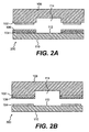
- Figure 2A shows a cross-sectional view of an embodiment of a microfluidic structure 200 that has two components capable of forming a seal between them.
- a removable structure 108 is temporarily sealed on top of a substrate 110.
- the substrate 110 includes an affinity surface 112 that supports, for example, a DNA or protein array.
- the removable structure 108 defines a microfluidic channel 114.
- the electrode 102 is located on a surface of the removable structure 108 and the electrode 104 is located on a surface of the substrate 110.
- the electrode 104 is covered with the elastic layer 106.
- the elastic layer 106 will insulate the major surface of the electrode 102 from liquid located in the microfluidic channel 114 that exists after the formation of a seal between the electrode 102 and the electrode 104.
- the electrode 102 may be covered with a thin layer of insulating material or with an elastic layer 106 (not shown in Figure 2A).
- the removable structure 108 is attached to the substrate 110 by aligning the electrode 102 with the electrode 104 and applying a voltage between the electrode 102 and the electrode 104.
- the electrostatic force between the electrodes will pull the electrode 102 toward the elastic layer covering the surface of the electrode 104.
- Contact between the electrode 102 and the elastic layer 106 on the electrode 104 forms a seal between the removable structure 108 and the substrate 110.
- the attachment of the removable structure 108 and the substrate 110 to form the microfluidic structure 200 closes the open section of the microfluidic channel 114 and allows the delivery of reagents, buffers, analytes, etc., as well as the performance of other procedures on the affinity surface 112 of the substrate 110.
- Figure 2B shows.another embodiment of a microfluidic structure 300 in which the electrode 102 is located on a surface of the removable structure 108 and the exposed surfaces of the electrode 102 are coated with the elastic layer 106.
- the electrode 104 is located on a surface of the substrate 110 and is not covered with any elastic layer.
- the elastic layer 106 fully insulates the electrode 102 from fluid located in the microfluidic channel 114.
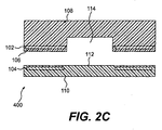
- Figure 2C shows another embodiment of a microfluidic structure 400 in which the electrode 104 is embedded in the substrate 110.
- the electrode 104 can be embedded by the manufacturing process of the substrate 110.
- the electrode 104 can be deposited on a surface of the substrate 110, and the surface then covered by a thin film of the same material as the substrate 110 or of another material.
- This substrate structure provides a flat surface that facilitates the performance of detection processes.
- Figure 2D shows another embodiment of a microfluidic structure 500 in which the opposed surfaces of the removable structure 108 and the substrate 110 are patterned with matching and interlocking features and the electrodes 102 and 104 are conformally deposited on the removable structure 108 and the substrate 110, respectively. At least one of the electrodes 102 and 104 is covered with elastic layer 106.
- the interlocking feature increases both the strength and hermeticity of the seal and facilitates the alignment between the removable structure 108 and the substrate 110.
- the contouring of the electrodes concentrates the electric field at the corners of the interlocking structure. Rounding the corners of the interlocking structure reduces the maximum field gradient and prevents electrostatic breakdown at the corners.
- the substrate 110 and removable patterning structure 108 may be fabricated using any organic material, inorganic materials or combination thereof that meets the thermal, mechanical, chemical and electrical insulation requirements of a particular application.
- organic materials include, but are not limited to, polystyrene, polypropylene, polyimide, cyclic olefin copolymer (COC), and polyetheretherketone (PEEK).
- inorganic materials include, but are not limited to, glass, ceramics, oxides, crystalline materials, and metals.
- the electrodes 102 and 104 are typically composed of one or more thin layers of a conducting material.
- the thickness of the electrodes is typically in the range of 20 nm - 500 ⁇ m, and more typically in the range of 100nm - 5 ⁇ m.
- the electrodes 102 and 104 are composed of one or more layers each of metal such as gold, silver, platinum, palladium, copper, aluminum or an alloy comprising one or more of such metals.
- the electrodes 102 and 104 comprise a layer of indium tin oxide (ITO).
- the electrodes 102 and 104 can also comprise one or more layers of respective elastic conducting materials or elastic conducting-polymer materials, such as polyaniline and polypyrrole.
- one or both of the removable structure 108 and the substrate 110 is made of a conducting material, such as a conducting polymer, doped silicon, or metal.
- the entire removable structure 108 or the substrate 110 serves as the electrode 102 or 104, respectively.
- the geometry of the electrodes 102 and 104 is typically optimized to provide an adequate sealing force for a given distribution of the internal channel pressure.
- the electrode geometry may also be optimized to provide an automatic alignment between the substrate 110 and the removable structure 108 in directions parallel to the plane of the major surface of the substrate 110.
- the material of the elastic layer 106 can be any suitable elastic insulating material.
- the material of the elastic layer 106 could advantageously have a high arcing resistance and a high dielectric constant, be chemically compatible with the application, and be hydrophobic, although these properties may not be advantageous in all applications.
- Examples of the material of the elastic layer 106 include, but are not limited to, rubber, thermoplastic rubber, silicone rubber, fluoroelastomer, acrylic, COC, urethanes, polymethylmethacrylate (PMMA), polycarbonate, polytetrafluoroethylene, polyvinylchloride (PVC), polydimethylsiloxane (PDMS), polysulfone, siloxanes, or polyamides. The selection of the material will vary according to the microfluidic device and the assay.
- the material of the elastic layer 106 may be spin-coated or stamped on the substrate surface, on top of the electrodes, or on both.
- the components thereof may be transparent, reflecting, or opaque depending on the optical requirements of the application.
- FIG. 3A illustrates another embodiment of a microfluidic structure in accordance with the invention incorporating an embodiment of an electrostatic sealing device.
- electrostatic sealing devices 310, 312, and 316 are used to regulate fluid flow in and between the microchannels 302, 304 and 306 of a microfluidic structure 600.
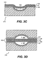
- FIG. 3B is a cross-sectional view of an embodiment of the electrostatic sealing device 310 along the line 3B-3B.
- the electrostatic sealing device 312 is similar in structure and will not be separately described.
- the electrostatic sealing device 310 is located on a U- or V-shaped microchannel 304 that is coated over a portion of its length with a channel electrode 105.
- the channel electrode is coated with an elastic layer 107.
- a lengthwise portion of the microchannel 304 is covered with an elastic membrane electrode 103.
- the surface of the membrane electrode 103 facing the channel electrode 105 is coated by the elastic layer 106.
- a voltage applied between the elastic membrane electrode 103 and the channel electrode 105 establishes an electric field that pulls the elastic membrane electrode 103 towards the channel electrode 105 in the direction shown by arrow C.
- the microchannel 304 has a U- or V-shaped cross-section area, the distance between the membrane electrode 103 and the channel electrode 105 is a maximum at the center of the microchannel 304 and becomes smaller towards the edges of the microchannel 304. Accordingly, the electrostatic pressure p is greatest at the edges of the microchannel 304, since the electrostatic pressure p is inversely proportional to the distance between the electrodes 103 and 105 (see equation (2) above).
- portions of the elastic membrane electrode 103 adjacent the edges of the microchannel 304 are pulled toward the channel electrode 105 once the electrostatic pressure p at the edge of the microchannel 304 reaches the required magnitude.
- the movement of the elastic membrane electrode 103 into the microchannel 304 reduces the distance between the elastic membrane electrode 103 and the channel electrode 105 and increases the strength of the electrostatic field between the electrodes 103 and 105.
- the increased electrostatic field strength in turn causes further movement of the elastic membrane electrode 103 into the microchannel.
- contact between the elastic membrane electrode 103 and the channel electrode 105 occurs initially at the edges of the microchannel 304 and moves progressively towards the center of the microchannel.
- the relative motion of the electrodes 103 and 105 as they come into contact is analogous to two zip fasteners moving in opposite directions from the edges of the microchannel 304 to meet at the center of the microchannel.
- the above-described "zipper” effect as the elastic membrane electrode 103 and the channel electrode 105 come into contact is opposed by the elasticity of the elastic membrane electrode 103 and the elastic layer 106, as well as by the pressure exerted by the fluid in the microchannel 304.
- the applied voltage needed to initiate the "zipper” effect is reduced by reducing the gap between the elastic membrane electrode 103 and the channel electrode 105 at the edges of the microchannel 304.
- the gap can be reduced by structuring the U- or V-shaped microchannel 304 to form a small contact angle ⁇ (see Figure 3B) with the membrane electrode 103 at the edges of the microchannel 304.
- the contact angle is less than 45°. In another embodiment, the contact angle is less than 30°.
- the electrostatic sealing device 310 described above can be used as a shut-off valve, which has only an on state or an off state, or as a regulating valve, which additionally has partially on states.
- the electrodes 103 and 105 may partially or fully seal the microchannel 304 and thus regulate fluid flow in the microchannel 304.
- the one of the elastic membrane electrode 103 and the channel electrode 105 that is at the higher voltage when a voltage is applied between the electrodes is coated with an elastic layer or a layer of another insulating material to prevent the fluid in the microchannel 304 from providing a leakage path from the higher voltage electrode to ground.
- FIG. 3D is a cross-sectional view of another microfluidic device in accordance with the invention incorporating an embodiment of an electronic sealing device 314.
- the electrostatic sealing device 314 is located on two U- or V-shaped microchannels 320 and 322 that are aligned with their open sections facing each other.
- the open sections are covered by a common elastic membrane electrode 103 coated on both sides with an elastic layer 106.
- Each of the microchannels 320 and 322 is coated over a section of its length opposite the elastic membrane electrode with a respective channel electrode 105.
- Each channel electrode is coated with an elastic layer 107.
- the elastic membrane electrode 103 is a common electrode and is moved into the microchannel 320 or into the microchannel 322, as shown by the arrows E and F, depending on which of the channel electrodes 105 has the voltage applied.
- the inlets of the microchannels 320 and 322 are connected to a common microchannel (not shown).
- the channel electrode 105 to which the voltage is applied selectively causes the microfluidic device to route fluid flowing in the common microchannel through the microchannel 320 or through the microchannel 322.
- voltage is applied to neither of the channel electrodes, the fluid flows through both of the microchannels.
- FIG. 3E is a cross-sectional view of an embodiment of the electrostatic sealing device 316 shown in Figure 3A along the section line 3E-3E.
- at least one of the elastic membrane electrode 103 and the channel electrode 105 is composed of electrode segments.
- both electrodes are composed of electrode segments.
- the electrostatic sealing device 316 has pairs of the electrode segments (pairs 103A and 105A, 103B and 105B, 103C and 105C and 103D and 105D) disposed in tandem along the length of the V- or U-shaped microchannel 302.
- a voltage sequentially applied between the electrode segment pairs 103A and 105A through 103D and 105D causes the electrostatic sealing device 316 to operate as a pump.
- the sequential sealing of the microchannel 302 by the electrode segment pairs 103A and 105A through 103D and 105D pushes the liquid in the microchannel 302 in the direction shown by the arrow.
- the pumping efficiency, and, hence the pressure generated can be controlled by the way in which the voltage is sequentially applied to the electrode segment pairs. For example, a longer interval between the times at which the voltage is applied to each electrode segment pair leads to a lower pumping efficiency.
- a shorter powering interval between the times at which the voltage is applied to each electrode segment pair results in a higher pumping efficiency because the electrostatic seal provided by the electrode segment pair from which the voltage is removed does not fully relax before the electrostatic seal provided by electrode segment pair to which the voltage is newly applied.
- Circuits that allow independent control of each electrode segment or electrode segment pair are well-known in the art. Such circuits allow an operator of the electrostatic sealing device 316 to apply the voltage to the electrode segments sequentially along the length of the microchannel 302. Algorithms that allow different powering intervals are also well-known in the art.
- the voltage is additionally applied to the electrode segment pair 103B and 105B before the voltage is removed from electrode segment pair 103A and 105A.
- the voltage is removed from electrode segment pair 103A and 105A after the time required for the voltage to fully establish the electrostatic seal between the electrode segment pair 103B and 105B.
- the applying sequence repeats with the application of the voltage to the electrode segment pair 103A and 105A.
- the voltage can be cumulatively applied to the electrode segment pairs in the sequence 103A and 105A through 103D and 105D.
- only one of the elastic membrane electrode and the channel electrode is composed of electrode segments disposed along the length of the microchannel 302.
- a channel electrode common to all the electrode segments 103A-103D is a provided by a continuous electrode coating located on the inner surface of the microchannel channel 302.
- the elastic membrane electrode remains composed of electrode segments 103A-103D as shown in Figure 3E.
- an electrode segment pair can be regarded as existing between each of the electrode segments 103A-103D and the portion of the common channel electrode opposite the electrode segment.
- Such embodiment of the electrostatic sealing device 316 works as a pump by sequentially applying a voltage between the common channel electrode and each of the electrode segments 103A-103D in a manner similar to that described above.
- the elastic membrane electrode may be structured as a common electrode and the channel electrode may be composed of electrode segments.
- Embodiments of the pump provided by the electrostatic sealing device 316 may be used to control fluid movement within the microfluidic device.
- the elastic membrane electrode 103 may deform in response to the pressure of the fluid in the microchannel 304, as shown in Figure 3F.
- the pressure may push the elastic membrane electrode 103 in the outward direction as indicated by the arrow D.
- the resulting increased cross-sectional area changes the flow resistance of the microchannel 304.
- this property of the electrostatic sealing device 310 may be desirable. In other applications, this property may be undesirable.
- Figure 3G shows another embodiment of the electrostatic sealing device 310 in which the outward movement of the elastic membrane electrode 103 is constrained by a rigid layer 111 disposed over the elastic membrane electrode 103.
- the rigid layer 111 is not attached to the elastic membrane electrode 103 and therefore does not constrain the movement of the elastic membrane electrode 103 into the microchannel 304 when a voltage is applied between the elastic membrane electrode and the channel electrode 105.
- the electrostatic sealing device can be used as a valve, a pump, a flow regulator, or a combination thereof.
- the microfluidic structures 200, 300, 400, 500 and 600 disclosed herein can be used in a variety of applications.
- Examples include, but are not limited to, detection of binding events such as cell-membrane, cell-cell, cell-substrate/receptor, antibody-antigen, hormone-receptor, small molecule-protein, polynucleotide-polynucleotide, and protein-polynucleotide binding events; detection of chemical modifications such as isomerization, oxidation, and reduction; and detection of biochemical reactions such as enzymatic modification (e.g., cleavage by proteases, phosphotases, lipases, endonucleases, exonucleases, and/or transferases).
- binding events such as cell-membrane, cell-cell, cell-substrate/receptor, antibody-antigen, hormone-receptor, small molecule-protein, polynucleotide-polynucleotide, and protein-polynucleotide binding events
- detection of chemical modifications such as isomerization, oxidation,
- microfluidic structures disclosed herein may be used to perform a variety of assays that include, but are not limited to, determination of enzymatic inhibition by a collection of compounds in solution; determination of substrates for an enzyme (fishing/selectivity), identifying binding partners for immobilized biomolecules (such as peptides, proteins, nucleic acids, antibodies, enzymes, glycoproteins, proteoglycans, and other biological materials, as well as chemical substances), identifying inhibitors of protein-protein, protein-small molecule or protein-receptor binding, determination of the activity of a collection of enzymes (in one or more than one well), and generating selectivity indices for inhibitors of enzymes or other biologically active molecules.
- assays include, but are not limited to, determination of enzymatic inhibition by a collection of compounds in solution; determination of substrates for an enzyme (fishing/selectivity), identifying binding partners for immobilized biomolecules (such as peptides, proteins, nucleic acids, antibodies, enzymes, glyco
Landscapes
- Engineering & Computer Science (AREA)
- Chemical & Material Sciences (AREA)
- Mechanical Engineering (AREA)
- Health & Medical Sciences (AREA)
- Dispersion Chemistry (AREA)
- General Engineering & Computer Science (AREA)
- Analytical Chemistry (AREA)
- General Health & Medical Sciences (AREA)
- Hematology (AREA)
- Clinical Laboratory Science (AREA)
- Chemical Kinetics & Catalysis (AREA)
- Microelectronics & Electronic Packaging (AREA)
- Physical Or Chemical Processes And Apparatus (AREA)
- Electrically Driven Valve-Operating Means (AREA)
- Micromachines (AREA)
Applications Claiming Priority (2)
| Application Number | Priority Date | Filing Date | Title |
|---|---|---|---|
| US10/701,502 US20050098750A1 (en) | 2003-11-06 | 2003-11-06 | Electrostatic sealing device and method of use thereof |
| US701502 | 2003-11-06 |
Publications (2)
| Publication Number | Publication Date |
|---|---|
| EP1531002A2 true EP1531002A2 (fr) | 2005-05-18 |
| EP1531002A3 EP1531002A3 (fr) | 2005-11-23 |
Family
ID=34435534
Family Applications (1)
| Application Number | Title | Priority Date | Filing Date |
|---|---|---|---|
| EP04019427A Withdrawn EP1531002A3 (fr) | 2003-11-06 | 2004-08-16 | Dispositif et procédé pour électrostatiquement étancher des dispositifs microfluidique |
Country Status (3)
| Country | Link |
|---|---|
| US (2) | US20050098750A1 (fr) |
| EP (1) | EP1531002A3 (fr) |
| JP (1) | JP2005140333A (fr) |
Families Citing this family (21)
| Publication number | Priority date | Publication date | Assignee | Title |
|---|---|---|---|---|
| US20050164373A1 (en) * | 2004-01-22 | 2005-07-28 | Oldham Mark F. | Diffusion-aided loading system for microfluidic devices |
| WO2008052363A1 (fr) * | 2006-11-03 | 2008-05-08 | Mcgill University | Microsoupape électrique et procédé de fabrication de celle-ci |
| US7863035B2 (en) * | 2007-02-15 | 2011-01-04 | Osmetech Technology Inc. | Fluidics devices |
| KR100917233B1 (ko) * | 2007-07-26 | 2009-09-16 | 한국전자통신연구원 | 표면 코팅된 고분자 구동기 및 그의 제조방법 |
| WO2013134741A2 (fr) | 2012-03-08 | 2013-09-12 | Cyvek, Inc. | Procédés et systèmes de fabrication de systèmes d'analyse de microréseaux, de mise en oeuvre d'analyses microfluidiques, et de surveillance et de balayage pour obtenir des résultats d'analyse microfluidique |
| US9855735B2 (en) | 2009-11-23 | 2018-01-02 | Cyvek, Inc. | Portable microfluidic assay devices and methods of manufacture and use |
| ES2649559T3 (es) | 2009-11-23 | 2018-01-12 | Cyvek, Inc. | Método y aparato para realizar ensayos |
| US9500645B2 (en) | 2009-11-23 | 2016-11-22 | Cyvek, Inc. | Micro-tube particles for microfluidic assays and methods of manufacture |
| US9759718B2 (en) | 2009-11-23 | 2017-09-12 | Cyvek, Inc. | PDMS membrane-confined nucleic acid and antibody/antigen-functionalized microlength tube capture elements, and systems employing them, and methods of their use |
| US9651568B2 (en) | 2009-11-23 | 2017-05-16 | Cyvek, Inc. | Methods and systems for epi-fluorescent monitoring and scanning for microfluidic assays |
| US9700889B2 (en) | 2009-11-23 | 2017-07-11 | Cyvek, Inc. | Methods and systems for manufacture of microarray assay systems, conducting microfluidic assays, and monitoring and scanning to obtain microfluidic assay results |
| US10065403B2 (en) | 2009-11-23 | 2018-09-04 | Cyvek, Inc. | Microfluidic assay assemblies and methods of manufacture |
| JP5286415B2 (ja) * | 2010-03-11 | 2013-09-11 | 株式会社キッツ | 高分子アクチュエータとこれを用いたバルブ |
| WO2012129455A2 (fr) | 2011-03-22 | 2012-09-27 | Cyvek, Inc | Dispositifs micro-fluidiques et leurs procédés de fabrication et d'utilisation |
| US8975193B2 (en) | 2011-08-02 | 2015-03-10 | Teledyne Dalsa Semiconductor, Inc. | Method of making a microfluidic device |
| CN106338544B (zh) * | 2015-07-09 | 2019-05-28 | 南京大学 | 一种模拟人肺呼吸运动系统的烟气分析装置 |
| WO2017046802A1 (fr) * | 2015-09-16 | 2017-03-23 | Technion Research & Development Foundation Limited | Dispositifs microfluidiques dynamiques et utilisation de ceux-ci |
| US10228367B2 (en) | 2015-12-01 | 2019-03-12 | ProteinSimple | Segmented multi-use automated assay cartridge |
| US20190142111A1 (en) * | 2017-11-10 | 2019-05-16 | Head Technology Gmbh | Liner for sports shoes |
| CN109027688B (zh) * | 2018-10-26 | 2021-04-30 | 郑州大学 | 一种低压液路集成块及其加工工艺 |
| EP3795252B1 (fr) * | 2019-09-19 | 2025-12-24 | Sharp Life Science (EU) Limited | Espaceur conducteur pour un dispositif microfluidique |
Family Cites Families (22)
| Publication number | Priority date | Publication date | Assignee | Title |
|---|---|---|---|---|
| US544890A (en) * | 1895-08-20 | Max frank | ||
| JPH02287477A (ja) * | 1989-04-28 | 1990-11-27 | Nec Corp | 電子写真式印刷機 |
| EP0498863B1 (fr) * | 1990-08-31 | 1995-07-26 | Westonbridge International Limited | Soupape equipee d'un detecteur de position et micropompe integree a ladite soupape |
| SE9100392D0 (sv) * | 1991-02-08 | 1991-02-08 | Pharmacia Biosensor Ab | A method of producing a sealing means in a microfluidic structure and a microfluidic structure comprising such sealing means |
| US5176358A (en) * | 1991-08-08 | 1993-01-05 | Honeywell Inc. | Microstructure gas valve control |
| US5994314A (en) * | 1993-04-07 | 1999-11-30 | Inhale Therapeutic Systems, Inc. | Compositions and methods for nucleic acid delivery to the lung |
| US5705018A (en) * | 1995-12-13 | 1998-01-06 | Hartley; Frank T. | Micromachined peristaltic pump |
| US6123316A (en) * | 1996-11-27 | 2000-09-26 | Xerox Corporation | Conduit system for a valve array |
| US6042345A (en) * | 1997-04-15 | 2000-03-28 | Face International Corporation | Piezoelectrically actuated fluid pumps |
| US5836750A (en) * | 1997-10-09 | 1998-11-17 | Honeywell Inc. | Electrostatically actuated mesopump having a plurality of elementary cells |
| US5901939A (en) * | 1997-10-09 | 1999-05-11 | Honeywell Inc. | Buckled actuator with enhanced restoring force |
| US6089853A (en) * | 1997-12-24 | 2000-07-18 | International Business Machines Corporation | Patterning device for patterning a substrate with patterning cavities fed by service cavities |
| US6089534A (en) * | 1998-01-08 | 2000-07-18 | Xerox Corporation | Fast variable flow microelectromechanical valves |
| DE50003276D1 (de) * | 1999-05-17 | 2003-09-18 | Fraunhofer Ges Forschung | Mikromechanische pumpe |
| US6568286B1 (en) * | 2000-06-02 | 2003-05-27 | Honeywell International Inc. | 3D array of integrated cells for the sampling and detection of air bound chemical and biological species |
| US6488828B1 (en) * | 2000-07-20 | 2002-12-03 | Roche Diagnostics Corporation | Recloseable biosensor |
| US7371563B2 (en) * | 2000-11-08 | 2008-05-13 | Surface Logix, Inc. | Peelable and resealable devices for biochemical assays |
| US6435840B1 (en) * | 2000-12-21 | 2002-08-20 | Eastman Kodak Company | Electrostrictive micro-pump |
| US7060227B2 (en) * | 2001-08-06 | 2006-06-13 | Sau Lan Tang Staats | Microfluidic devices with raised walls |
| US7075162B2 (en) * | 2001-08-30 | 2006-07-11 | Fluidigm Corporation | Electrostatic/electrostrictive actuation of elastomer structures using compliant electrodes |
| US6729856B2 (en) * | 2001-10-09 | 2004-05-04 | Honeywell International Inc. | Electrostatically actuated pump with elastic restoring forces |
| US7090471B2 (en) * | 2003-01-15 | 2006-08-15 | California Institute Of Technology | Integrated electrostatic peristaltic pump method and apparatus |
-
2003
- 2003-11-06 US US10/701,502 patent/US20050098750A1/en not_active Abandoned
-
2004
- 2004-08-16 EP EP04019427A patent/EP1531002A3/fr not_active Withdrawn
- 2004-11-08 JP JP2004323167A patent/JP2005140333A/ja active Pending
-
2005
- 2005-12-27 US US11/318,994 patent/US20060102862A1/en not_active Abandoned
Also Published As
| Publication number | Publication date |
|---|---|
| US20060102862A1 (en) | 2006-05-18 |
| US20050098750A1 (en) | 2005-05-12 |
| EP1531002A3 (fr) | 2005-11-23 |
| JP2005140333A (ja) | 2005-06-02 |
Similar Documents
| Publication | Publication Date | Title |
|---|---|---|
| EP1531002A2 (fr) | Dispositif et procédé pour électrostatiquement étancher des dispositifs microfluidique | |
| US6685809B1 (en) | Methods for forming small-volume electrical contacts and material manipulations with fluidic microchannels | |
| US9103761B2 (en) | Methods and devices for electronic sensing | |
| US7052594B2 (en) | Devices and methods for controlling fluid flow using elastic sheet deflection | |
| US5869004A (en) | Methods and apparatus for in situ concentration and/or dilution of materials in microfluidic systems | |
| Choi et al. | Development and characterization of microfluidic devices and systems for magnetic bead-based biochemical detection | |
| Huang et al. | Ultrafast high-pressure AC electro-osmotic pumps for portable biomedical microfluidics | |
| AU746335B2 (en) | Micropump | |
| JP5964881B2 (ja) | プリント回路基板上の液滴操作装置及び方法 | |
| US6655923B1 (en) | Micromechanic pump | |
| EP1400600A1 (fr) | Dispositif intégrén pour les analyses biologiques | |
| US20060086309A1 (en) | Recirculating fluidic network and methods for using the same | |
| US20090120796A1 (en) | Electrokinetic concentration device and methods of use thereof | |
| WO2005012874A2 (fr) | Dispositifs de transport de materiaux nanostructures et leur fabrication par application de revetements moleculaires a des canaux a echelle nanometrique | |
| US20060169588A1 (en) | Microfluidic device and methods for focusing fluid streams using electroosmotically induced pressures | |
| US20010035351A1 (en) | Cross channel device for serial sample injection | |
| WO2012085728A1 (fr) | Dispositif microfluidique comprenant un moyen de commande du flux de fluide | |
| Joo et al. | A rapid field-free electroosmotic micropump incorporating charged microchannel surfaces | |
| US20150300985A1 (en) | Fluid handling device and fluid handling method | |
| US20020174686A1 (en) | Method for producing microchannels having circular cross-sections in glass | |
| Jang et al. | Fabrication of microfluidic devices for packaging CMOS MEMS impedance sensors | |
| Zhang | Integration of a polarizable interface for electrophoretic separation in a microfluidic device | |
| TW202325645A (zh) | 電子裝置 | |
| Maltezos | Microfluidic Devices for Accessible Medical Diagnostics |
Legal Events
| Date | Code | Title | Description |
|---|---|---|---|
| PUAI | Public reference made under article 153(3) epc to a published international application that has entered the european phase |
Free format text: ORIGINAL CODE: 0009012 |
|
| AK | Designated contracting states |
Kind code of ref document: A2 Designated state(s): AT BE BG CH CY CZ DE DK EE ES FI FR GB GR HU IE IT LI LU MC NL PL PT RO SE SI SK TR |
|
| AX | Request for extension of the european patent |
Extension state: AL HR LT LV MK |
|
| PUAL | Search report despatched |
Free format text: ORIGINAL CODE: 0009013 |
|
| AK | Designated contracting states |
Kind code of ref document: A3 Designated state(s): AT BE BG CH CY CZ DE DK EE ES FI FR GB GR HU IE IT LI LU MC NL PL PT RO SE SI SK TR |
|
| AX | Request for extension of the european patent |
Extension state: AL HR LT LV MK |
|
| 17P | Request for examination filed |
Effective date: 20060425 |
|
| AKX | Designation fees paid |
Designated state(s): DE FR GB |
|
| 17Q | First examination report despatched |
Effective date: 20060821 |
|
| RAP1 | Party data changed (applicant data changed or rights of an application transferred) |
Owner name: AGILENT TECHNOLOGIES, INC. |
|
| STAA | Information on the status of an ep patent application or granted ep patent |
Free format text: STATUS: THE APPLICATION IS DEEMED TO BE WITHDRAWN |
|
| 18D | Application deemed to be withdrawn |
Effective date: 20090303 |