EP1531027A1 - Elément de serrage et procédé pour serrer des pièces, des outils, des moules ou des dispositifs - Google Patents
Elément de serrage et procédé pour serrer des pièces, des outils, des moules ou des dispositifs Download PDFInfo
- Publication number
- EP1531027A1 EP1531027A1 EP04105691A EP04105691A EP1531027A1 EP 1531027 A1 EP1531027 A1 EP 1531027A1 EP 04105691 A EP04105691 A EP 04105691A EP 04105691 A EP04105691 A EP 04105691A EP 1531027 A1 EP1531027 A1 EP 1531027A1
- Authority
- EP
- European Patent Office
- Prior art keywords
- piston
- clamping
- bore
- positioning means
- pivoting
- Prior art date
- Legal status (The legal status is an assumption and is not a legal conclusion. Google has not performed a legal analysis and makes no representation as to the accuracy of the status listed.)
- Withdrawn
Links
- 238000000034 method Methods 0.000 title claims description 5
- 230000006835 compression Effects 0.000 claims abstract description 12
- 238000007906 compression Methods 0.000 claims abstract description 12
- XEEYBQQBJWHFJM-UHFFFAOYSA-N Iron Chemical compound [Fe] XEEYBQQBJWHFJM-UHFFFAOYSA-N 0.000 claims description 29
- 229910052742 iron Inorganic materials 0.000 claims description 14
- 230000008878 coupling Effects 0.000 claims 2
- 238000010168 coupling process Methods 0.000 claims 2
- 238000005859 coupling reaction Methods 0.000 claims 2
- 230000000630 rising effect Effects 0.000 description 6
- 238000005452 bending Methods 0.000 description 4
- 230000008719 thickening Effects 0.000 description 4
- 238000005553 drilling Methods 0.000 description 3
- 241000251131 Sphyrna Species 0.000 description 2
- 238000006073 displacement reaction Methods 0.000 description 2
- 210000003746 feather Anatomy 0.000 description 2
- 239000012530 fluid Substances 0.000 description 2
- 230000002040 relaxant effect Effects 0.000 description 2
- 238000007789 sealing Methods 0.000 description 2
- 230000001195 anabolic effect Effects 0.000 description 1
- 239000003795 chemical substances by application Substances 0.000 description 1
- 238000011109 contamination Methods 0.000 description 1
- 230000003111 delayed effect Effects 0.000 description 1
- 239000012535 impurity Substances 0.000 description 1
- 230000001939 inductive effect Effects 0.000 description 1
- 230000035515 penetration Effects 0.000 description 1
Images

Classifications
-
- B—PERFORMING OPERATIONS; TRANSPORTING
- B25—HAND TOOLS; PORTABLE POWER-DRIVEN TOOLS; MANIPULATORS
- B25B—TOOLS OR BENCH DEVICES NOT OTHERWISE PROVIDED FOR, FOR FASTENING, CONNECTING, DISENGAGING OR HOLDING
- B25B5/00—Clamps
- B25B5/06—Arrangements for positively actuating jaws
- B25B5/061—Arrangements for positively actuating jaws with fluid drive
Definitions
- the invention relates to a clamping element for clamping workpieces, Tools, molds or devices on machine tables or pallets, with a movable positioning means and a movable on the positioning means guided clamping piece. Furthermore, the invention relates to a method for Clamping workpieces, tools or devices with such Clamping element.
- Such clamping elements are z. B. Linearspanner, as described in DE 37 33 676 A1 disclosed, or swing clamps, for example, according to DE 101 27 214 A1.
- the well-known from DE 37 33 676 A1 linear clamp has a linear over a to exciting workpiece movable positioning, namely a hydraulic actuated piston.
- This piston carries at its free end the clamping piece, which is connected via wedge surfaces movable with the piston.
- the clamping piece When extending of the piston, the clamping piece is driven against a stop. Then the Piston further moved over the clamping piece, so that the clamping piece moved due to the wedge surfaces transversely to the piston and against the exciting Workpiece or the like is pressed.
- the clamping element develops a Transverse force depending on the force acting on the piston and the angle of the Wedge surface over which this force on the clamping piece and thus on the workpiece or the like is transmitted.
- the Indian DE 101 27 214 A1 shown pivoting has as positioning a in a housing pivotally mounted and retractable mounted, hydraulically actuated swivel piston.
- the oscillating piston controlled by spiral grooves on the oscillating piston, in the Pivoted clamping position.
- the piston is over the remainder of the stroke retracted linearly and thereby the workpiece by means of a swivel piston attached clamping iron, on which the clamping piece is attached, tense.
- the invention is based on the problem, a clamping element and a method to create, in which, does not affect the size of the generated clamping force unfavorable is the length of a clamp or a positioning means on this acting lateral forces and bending moments.
- the clamping element according to the invention is characterized characterized in that the clamping piece during the movement of the positioning means is locked, such that it is only at the end of the movement of the positioning is operable.
- the inventive method is characterized in that the clamping piece is actuated only at the end of the movement of the positioning means.
- the invention thus ensures that the piston is completely complete extended or the swing piston is completely pivoted. Only at; only when Standstill of the (swing) piston in the end position, the clamping piece is actuated and against the workpiece or the like for clamping the same driven. Only in this moment occur lateral forces and a bending moment on the (swing) piston on. The (swing) piston is then already quiet, so that it no longer to a increased friction comes. Since the clamping piece is operated separately, is the Clamping force independent of the overhang of the clamping point freely selectable.
- a constructive development of the invention is suitable for locking or locking the clamping piece during the movement of the positioning means especially a return bolt.
- This is preferably by a compression spring in biased its locking position, so that is always the basic position biased position results. In case of failure of the pressure medium supply is ensured that the clamping piece is locked.
- the return bolt itself engages a development of the invention in a recess in the clamping piece. there the recess may have a bulge, so that for releasing the Return bolt from the locking position required compressive force is increased and so the certainty that the return bolt is not unintentional from the locked position escapes, is still enlarged.
- the recess may be provided with a slope so that Actuate the return bolt in the direction of the clamping piece the clamping piece is retracted. This is a separate actuating means for the Clamp in the retraction of the same superfluous.
- the return bolt itself is included preferably pressure-medium-actuated.
- Pressure chambers for the clamping piece and for the return bolt correspond preferably with pressure chambers for actuating the positioning in the one or each other direction. This allows the entire clamping element with only two Pressure medium connections, a connection for clamping and a connection to the Loosen, be supplied.
- a cylindrical positioning means can be inclined positions of Realize clamping piece in which the positioning means is rotated about its longitudinal axis becomes. However, the positioning should but in its respective inclination be fixed.
- the positioning means for one a hole for receiving the return bolt and the other one further bore with a widening to accommodate a positioning pin having. At least this hole is off-center and serves to over the Positioning pin to fix the angular position of the positioning.
- the bore for receiving the Positioning pin at the same time a pressure medium channel for connecting the pressure chamber for the clamping piece with the pressure space for the positioning means. separate Holes are thereby avoided. To release the channel that should Positioning agent thereby be provided with a flattening.
- the positioning means itself can be formed in one piece, in which case it frontally so to speak from the rear, so of the later clamping piece turned away side is inserted into its housing. Then it will be still screwed a socket for receiving the clamping piece and the Inserted clamping piece.
- positioning form two parts, namely with a screwed-on piston ring. In this Case, the positioning means from the other side, that of the later Inserted end face turned into its housing and then from screwed on the other side of the piston ring. This variant is something more expensive, but offers the advantage of providing larger strokes for the clamping piece too can.
- Some embodiments of the invention are as so-called swing clamps educated.
- a pivoting movement of the swing clamp on a Axialhub a reciprocating executed on which a clamping iron, the present case corresponds to the positioning, is attached.
- the clamping iron So also performs a height movement.
- a longitudinal axis immovable swivel mast This is rotatable clamped between a swivel base and a pivot bushing.
- Within the swivel base and the swivel mast are frontally to each other arranged corresponding holes in which a pivoting piston slidably arranged.
- This has the usual spiral groove over which the Pivoting movement is generated.
- a longitudinal groove and a so cooperating gear means, in particular a pin or a ball is transmit this pivoting movement on the pivot mast.
- Such a Swing clamp builds flat. The required clamping movement is alone by achieved the lowering of the clamping piece.
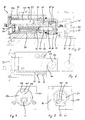
- the tensioning element shown in FIGS. 1 to 4, namely linear tensioner 20, has a guided in a housing 21 piston rod 22 as a positioning means.
- the piston rod 22 is guided in a housing bore 23 and through a sealing ring, namely an O-ring 24, sealed relative to the housing 21.
- a scraper ring 25 on the free end face of the housing bore 23 prevents Chips or similar impurities enter the housing bore 23.
- the housing bore 23 merges into a bore 26 of larger diameter. Therefore, on the rear end of the piston rod 22, a piston ring 27 with Screwed to the bore 26 corresponding diameter. Of the Piston ring 27 is opposite in a conventional manner by O-rings 28 and 29 the housing 21 and the piston rod 22 sealed. Finally, in the Bore 26, a lid 30 screwed to close the same and also sealed by an O-ring 31 opposite the housing 21.
- the piston rod 22 carries at its free, protruding from the housing 21 End a hammer head 32 in which a transverse piston 33 is guided as a clamping piece.
- the transverse piston 33 is in turn by an O-ring 34 opposite to the Hammer head 32 sealed.
- a pressure chamber 35 which via an angular bore 36 with a Pressure chamber between the piston rod 22 and the piston ring 27 on the one hand and the lid 30 communicates.
- the angular bore 36 is at its other, the Hammerhead 32 associated end closed by a plug 38.
- a return pin 40 is guided in a bore 39 and secured against the bore 39.
- the return bolt 40 is supported by a Compression spring 41 facing against a screw plug 42 on the lid 30 End of the bore 39 from.
- the closure screw 42 is opposite the bore 39th also sealed, so that the space between the screw plug 42 and the Return bolt 40 forms a pressure chamber 43.
- the return bolt 40 engages its tip 44 in a recess 45 laterally on the transverse piston 33 a.
- the clamping element 20 described so far operates as follows: For clamping a Workpiece 46 on a machine table 47 or the like is first of Pressure chamber 37 between the lid 30 on the one hand and the piston ring 27 and the Piston rod 22 on the other hand acted upon by pressure medium (Connection holes 48). The piston rod 22 now moves in the dash-dotted lines shown end position. Since the pressure in the pressure chamber 37 over the Angle bore 36 also propagates into the pressure chamber 35 in the hammer head 32 must be prevented that the transverse piston 33 is already extended. This prevents the prestressed by the compression spring 41 return bolt 40.
- in the housing suitable sensors, for example inductive or capacitive pickups 53 and 54 be arranged. With the help of a recessed in the piston rod 22 Magnets 55 or holes, the rear transducer 54 reports the retracted position and the hammerhead-side pickup 53 the extended Position of the piston rod 22.
- the piston rod 22 and corresponding to the piston ring 27 have a round Cross-section on. Accordingly, the holes 23 and 26 with round Cross section formed. It is thus possible, the piston rod 22 to their To twist longitudinal axis and oblique clamping positions, for example, as in Fig. 3, to enable.
- suitable means may be provided be to lock the piston rod 22 in their respective angular position. This happens in the specific case via a positioning pin 119, which in a Expansion 120 of the angular bore 36 engages.
- the positioning pin 119 is at its Flattened top, so that a channel 121 is formed for the pressure medium.
- the Positioning pin 119 continues to engage in a blind bore 122 in the lid 30 and positioned so the piston rod 22 against the lid 30.
- the lid 30 also determines the angular position of the piston rod 22, wherein the Cover 30 optionally on tuning discs in this angular position when Screwed into the housing 21 countered, or by clamping screws in his Situation is recorded.
- a variant of this clamping element is shown, in which the Clamping element 20 on the machine table 47 by means of fastening screws 56th is screwed on.
- the housing 21 is provided with a Flange 57 provided so that the clamping element 20 with its hammer head 32nd protrude through a plate bore or through the bore of a stand 58 and with can be screwed (fixing screws 59).
- the same components are therefore designated by the same reference numerals.
- the main difference is that no separately screwed on piston ring is provided. Rather, the piston rod 61 is integrally formed with a Thickening 62 in the rear, the lid 30 facing area. Because the Piston rod 61 now from behind with unscrewed cover 30 in the housing 21st must be used, it also has no pronounced hammer head. Rather, in the bore for the transverse piston 33 only from below one Socket 63 is used, which also has a scraper ring 64, the penetration of Prevents soiling, carries.
- the maximum extension stroke H 1 of the piston rod 61 is additionally located. It is easy to see that this maximum stroke H 1 corresponds to the length of the pressure chamber 50 for the retraction movement of the piston rod 61 in the retracted state of the piston rod 61. Furthermore, the stroke H 2 of the transverse piston 33 is indicated.
- the linear tensioner 60 differs from the linear tensioner 20 nor in that the connection holes 48 and 51 with leads A and B in Machine table 47 correspond.
- This variant is particularly suitable when multiple linear clamp 60 with a common pressure medium supply be served simultaneously.
- this variant also offers when the linear tensioner 60 instead of on a machine table 47 on a Workpiece change pallet is attached. In such cases, the Pressure medium supply often also on the workpiece change pallet.
- the linear tensioners 20 and 60 described so far are always advantageous can be used when workpieces 46 with a large extension stroke of Piston rod 22 and 61 to be clamped. This is, however, due spatial conditions on machine tools or the like is not always possible. In such cases, then swing clamps are used, in which a Clamp 77 pivoted about the workpiece to be clamped 46 and then by lowering the clamping iron 77, the workpiece 46 is tensioned. Also in such swing vices, the invention can be advantageously integrated, such as will be explained below in the variants shown in FIGS. 9 to 15.
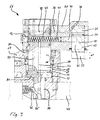
- the swing clamp 66 shown in FIG. 9 has a pivot housing 67, in FIG which a pivot piston 68 is guided. Specifically, the swing piston 68 on the one hand in a cylinder bore 69 and on the other hand in a Cylinder bore 69 occlusive guide bushing 70 out and in itself sealed in a known manner.
- the pivoting piston 68 has a plate-like Thickening 71 on which the cylinder bore 69 in two pressure chambers 72 and 73 divided. In this case, the pressure chamber 72 via the connection bore A with pressurized oil for clamping in the manner to be described in more detail below, while the pressure chamber 73 via the connection bore B to relax with Pressure medium is supplied.
- the pivoting piston 68 continues downward in a narrower pin 74, which in this case a smaller diameter than that Swivel piston 68 has.
- the pin 74 bears one of swing clamps known spiral groove 75, which also in a conventional manner with a fixed, pressure spring loaded ball 76 cooperates and by the stroke of Swivel piston 68 provides for a pivoting movement thereof.
- a clamping iron 77 At the free end of the Swivel piston 68 is a clamping iron 77 non-rotatable with the Swivel piston 68 attached.
- This clamp iron 77 carries the analogous Piston rod 22 of the linear tensioner 20 and the piston rod 61 of the Linearspanners 60 the transverse piston 33, so that here the same parts with the same Reference numerals are designated.
- the pressure chamber 35 for the extension movement of the transverse piston 33 corresponds via the angular bore 36 with a transverse bore 78 in the rotary piston 68, which again via a riser 79 with the pressure chamber 72 for the Clamping movement of the swing clamp 66 corresponds.
- the pressure chamber 43 corresponds via a riser 80 and a transverse bore 81 with the Pressure chamber 73 for relaxing the swing clamp 66.
- the pressure chamber 43 goes in the present case transversely through the pivot piston 68 therethrough. He will on the one hand, as already described above with reference to the linear tensioners 20 and 60, through the locking screw 42 and on the other hand by the return bolt 40th limited and takes on the compression spring 41. Locking screw 42 and Return bolts 40 are arranged in clamping iron 77.
- the operation of the swing clamp 66 is analogous to the operation of the Linear tensioner 20 or 60.
- To tighten the swing clamp 66 is on the Connecting bore A of the pressure chamber 72 applied with pressure medium.
- the rises Pressure which extends through the holes 79, 78 and 36 in the pressure chamber 35th propagates so far that the biasing force of the spring 41 overcome and the Return bolt 40 to the rear on the pivoting piston 68 to due to Bevel 49 is pressed.
- the transverse piston 33 is lowered onto the workpiece and tense this.
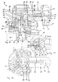
- the swing clamp 82 has a pivot base 83, on the means of a Socket 84 a pivoting mast 85 is mounted.
- the mast 85 is here relative to the pivot base 83 rotatable about its longitudinal axis.
- a displacement 86 is formed, which is about half of its length respectively in the swivel mast 85 and swivel base 83rd located.
- a pivot piston 87 is guided. This instructs its outer periphery a spiral groove 88, which with a spring-loaded Ball 125 cooperates, which in obstruction of the pivoting movement of Clamping iron 77 as overload fuse from the spiral groove 88 disengages.
- Fig. 11 shows a possible combination of valves, which ensures that the pressure chamber 35 is supplied with pressure medium only when the Swivel piston 87 has reached its upper end position.
- valve combination is always advantageous when lifting the pivoting piston in the pressure chamber 89 required pressure in about the Extending the transverse piston 33 required pressure in the pressure chamber 35 corresponds, or the spring pressure on the return bolt 40 is insufficient.
- Fig. 11 is centrally in the pivot mast 85 below a spring 100 the Riser hole 95 recognizable.
- the spring 100 presses a valve ball 101 into its seat, so that a bore 102 is closed. Will now through the riser 95th Added pressure medium, presses the resulting pressure continues on the Ball 101 and closes the valve.
- the pressure medium passes through a Abzweigbohrung 103 against another spring-loaded valve ball 104 and presses this back against the force of the spring 105, so that a channel is released.
- the Pressure fluid now enters a transverse bore 106 and from there via a Ring groove 107 in the angular bore 36.
- the pressure chamber 35 above the Querkolbens 33 is acted upon by pressure medium.
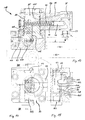
- the swivel mast 85 is not operated via a swivel piston with spiral groove. Rather, the pivoting piston 109 is here in the pivot base 83 below the Swivel mast 85 arranged. He has at its top a transverse Groove 110 into which a pin 111 engages. The pin 111 is connected by a compression spring 112 biased against the pivot piston 109 and can by the trapezoidal Embodiment of the groove 110 in a disability of Disengage clamping swivel movement.
- a pressure chamber 113 is pressurized via the connection bore A, is the pivot piston 109 in the illustration of FIG. 14 and 15 upwards pressed. He takes the pin 111 with it and thereby turns the Slewing mast 85. Except in the pressure chamber 113, the pressure medium passes through a Ring groove 114 in a channel 115 and from there via a further annular groove 116 in the Angular bore 36. As a result, the pressure chamber 35, as already several times described, supplied for the transverse piston 33 with pressure medium.
Landscapes
- Engineering & Computer Science (AREA)
- Mechanical Engineering (AREA)
- Jigs For Machine Tools (AREA)
Applications Claiming Priority (2)
| Application Number | Priority Date | Filing Date | Title |
|---|---|---|---|
| DE10353531 | 2003-11-14 | ||
| DE2003153531 DE10353531A1 (de) | 2003-11-14 | 2003-11-14 | Spannelement und Verfahren zum Spannen von Werkstücken, Werkzeugen, Formen oder Vorrichtungen |
Publications (1)
| Publication Number | Publication Date |
|---|---|
| EP1531027A1 true EP1531027A1 (fr) | 2005-05-18 |
Family
ID=34428762
Family Applications (1)
| Application Number | Title | Priority Date | Filing Date |
|---|---|---|---|
| EP04105691A Withdrawn EP1531027A1 (fr) | 2003-11-14 | 2004-11-11 | Elément de serrage et procédé pour serrer des pièces, des outils, des moules ou des dispositifs |
Country Status (2)
| Country | Link |
|---|---|
| EP (1) | EP1531027A1 (fr) |
| DE (1) | DE10353531A1 (fr) |
Cited By (3)
| Publication number | Priority date | Publication date | Assignee | Title |
|---|---|---|---|---|
| CN109318155A (zh) * | 2018-11-16 | 2019-02-12 | 东莞市沃德精密机械有限公司 | 定位装置及具有该装置的载具 |
| CN109579890A (zh) * | 2018-12-24 | 2019-04-05 | 南京东智安全科技有限公司 | 一种压式开合、弹性全夹持的传感器夹具 |
| WO2025021349A1 (fr) * | 2023-07-21 | 2025-01-30 | Römheld GmbH Friedrichshütte | Dispositif de serrage pour serrer un objet |
Citations (3)
| Publication number | Priority date | Publication date | Assignee | Title |
|---|---|---|---|---|
| US3578306A (en) * | 1969-06-05 | 1971-05-11 | Kenneth C Smith | Air pressure operated clamp |
| US4265434A (en) * | 1979-08-08 | 1981-05-05 | Barry Wright Corporation | Hydraulic clamp |
| DE3733676A1 (de) * | 1987-10-05 | 1989-04-20 | Roemheld A Gmbh & Co Kg | Hydraulisches spannelement |
-
2003
- 2003-11-14 DE DE2003153531 patent/DE10353531A1/de not_active Withdrawn
-
2004
- 2004-11-11 EP EP04105691A patent/EP1531027A1/fr not_active Withdrawn
Patent Citations (3)
| Publication number | Priority date | Publication date | Assignee | Title |
|---|---|---|---|---|
| US3578306A (en) * | 1969-06-05 | 1971-05-11 | Kenneth C Smith | Air pressure operated clamp |
| US4265434A (en) * | 1979-08-08 | 1981-05-05 | Barry Wright Corporation | Hydraulic clamp |
| DE3733676A1 (de) * | 1987-10-05 | 1989-04-20 | Roemheld A Gmbh & Co Kg | Hydraulisches spannelement |
Cited By (4)
| Publication number | Priority date | Publication date | Assignee | Title |
|---|---|---|---|---|
| CN109318155A (zh) * | 2018-11-16 | 2019-02-12 | 东莞市沃德精密机械有限公司 | 定位装置及具有该装置的载具 |
| CN109318155B (zh) * | 2018-11-16 | 2024-05-28 | 广东沃德精密科技股份有限公司 | 定位装置及具有该装置的载具 |
| CN109579890A (zh) * | 2018-12-24 | 2019-04-05 | 南京东智安全科技有限公司 | 一种压式开合、弹性全夹持的传感器夹具 |
| WO2025021349A1 (fr) * | 2023-07-21 | 2025-01-30 | Römheld GmbH Friedrichshütte | Dispositif de serrage pour serrer un objet |
Also Published As
| Publication number | Publication date |
|---|---|
| DE10353531A1 (de) | 2005-07-07 |
Similar Documents
| Publication | Publication Date | Title |
|---|---|---|
| DE4042070C2 (de) | Druckmittelbetriebener Kraftschrauber | |
| DE2741166C2 (de) | Vorrichtung zur Betätigung eines Spannkopfs | |
| EP2011605B1 (fr) | Outil manuel actionné hydrauliquement | |
| DE2639214C3 (de) | Bohrfutter | |
| DE4028595C2 (fr) | ||
| DE3784869T2 (de) | Hydraulische spannvorrichtung. | |
| DE2807677B2 (de) | Hydraulisches Schraubgerät | |
| DE69213570T2 (de) | Spannvorrichtung | |
| DE2656210C3 (de) | Bohrstranghalter für Gesteinsbohrgeräte | |
| EP1956183B1 (fr) | Tête de serrage pour un élément de tiges | |
| EP1531027A1 (fr) | Elément de serrage et procédé pour serrer des pièces, des outils, des moules ou des dispositifs | |
| EP3948013B1 (fr) | Arrangement support de selle réglable | |
| EP0299477A1 (fr) | Outil à main à fonctionnement hydraulique | |
| EP2602061B1 (fr) | Dispositif d'actionnement | |
| DE10252549A1 (de) | Druckmittelbetätigter Schwenkspanner sowie Steuerung für einen solchen Schwenkspanner | |
| DE9405667U1 (de) | Kraftschrauber | |
| DE4042154C2 (de) | Druckbetriebener Kraftschrauber | |
| DE2516454A1 (de) | Druckmittelbetaetigte presse zur spanlosen formgebung | |
| DE2232872A1 (de) | Vorrichtung zur begrenzung einer durch hebelwirkung zu uebertragenden kraft | |
| DE29914202U1 (de) | Nietsetzwerkzeug mit Hubeinstellung | |
| DE10206600B4 (de) | Mehrstufenhubzylinder | |
| EP0554760A1 (fr) | Multiplication de pression hydropneumatique | |
| DE202007010794U1 (de) | Spanneinrichtung | |
| DE4122181C1 (fr) | ||
| DE19842181B4 (de) | Vorrichtung zur Bildung eines Durchlasses für Rohre im Erdreich |
Legal Events
| Date | Code | Title | Description |
|---|---|---|---|
| PUAI | Public reference made under article 153(3) epc to a published international application that has entered the european phase |
Free format text: ORIGINAL CODE: 0009012 |
|
| AK | Designated contracting states |
Kind code of ref document: A1 Designated state(s): AT BE BG CH CY CZ DE DK EE ES FI FR GB GR HU IE IS IT LI LU MC NL PL PT RO SE SI SK TR |
|
| AX | Request for extension of the european patent |
Extension state: AL HR LT LV MK YU |
|
| 17P | Request for examination filed |
Effective date: 20051118 |
|
| AKX | Designation fees paid |
Designated state(s): AT BE BG CH CY CZ DE DK EE ES FI FR GB GR HU IE IS IT LI LU MC NL PL PT RO SE SI SK TR |
|
| GRAP | Despatch of communication of intention to grant a patent |
Free format text: ORIGINAL CODE: EPIDOSNIGR1 |
|
| STAA | Information on the status of an ep patent application or granted ep patent |
Free format text: STATUS: THE APPLICATION IS DEEMED TO BE WITHDRAWN |
|
| 18D | Application deemed to be withdrawn |
Effective date: 20090613 |