EP1531208A2 - Leitungssystem zum Ableiten von Flüssigkeit - Google Patents
Leitungssystem zum Ableiten von Flüssigkeit Download PDFInfo
- Publication number
- EP1531208A2 EP1531208A2 EP04025417A EP04025417A EP1531208A2 EP 1531208 A2 EP1531208 A2 EP 1531208A2 EP 04025417 A EP04025417 A EP 04025417A EP 04025417 A EP04025417 A EP 04025417A EP 1531208 A2 EP1531208 A2 EP 1531208A2
- Authority
- EP
- European Patent Office
- Prior art keywords
- pipe
- groove
- conduit system
- elements
- clamping element
- Prior art date
- Legal status (The legal status is an assumption and is not a legal conclusion. Google has not performed a legal analysis and makes no representation as to the accuracy of the status listed.)
- Granted
Links
Images


Classifications
-
- E—FIXED CONSTRUCTIONS
- E04—BUILDING
- E04D—ROOF COVERINGS; SKY-LIGHTS; GUTTERS; ROOF-WORKING TOOLS
- E04D13/00—Special arrangements or devices in connection with roof coverings; Protection against birds; Roof drainage ; Sky-lights
- E04D13/04—Roof drainage; Drainage fittings in flat roofs, balconies or the like
- E04D13/064—Gutters
- E04D13/0645—Connections between gutter and down pipe
-
- E—FIXED CONSTRUCTIONS
- E04—BUILDING
- E04D—ROOF COVERINGS; SKY-LIGHTS; GUTTERS; ROOF-WORKING TOOLS
- E04D13/00—Special arrangements or devices in connection with roof coverings; Protection against birds; Roof drainage ; Sky-lights
- E04D13/04—Roof drainage; Drainage fittings in flat roofs, balconies or the like
- E04D13/08—Down pipes; Special clamping means therefor
-
- F—MECHANICAL ENGINEERING; LIGHTING; HEATING; WEAPONS; BLASTING
- F16—ENGINEERING ELEMENTS AND UNITS; GENERAL MEASURES FOR PRODUCING AND MAINTAINING EFFECTIVE FUNCTIONING OF MACHINES OR INSTALLATIONS; THERMAL INSULATION IN GENERAL
- F16L—PIPES; JOINTS OR FITTINGS FOR PIPES; SUPPORTS FOR PIPES, CABLES OR PROTECTIVE TUBING; MEANS FOR THERMAL INSULATION IN GENERAL
- F16L21/00—Joints with sleeve or socket
- F16L21/08—Joints with sleeve or socket with additional locking means
-
- F—MECHANICAL ENGINEERING; LIGHTING; HEATING; WEAPONS; BLASTING
- F16—ENGINEERING ELEMENTS AND UNITS; GENERAL MEASURES FOR PRODUCING AND MAINTAINING EFFECTIVE FUNCTIONING OF MACHINES OR INSTALLATIONS; THERMAL INSULATION IN GENERAL
- F16L—PIPES; JOINTS OR FITTINGS FOR PIPES; SUPPORTS FOR PIPES, CABLES OR PROTECTIVE TUBING; MEANS FOR THERMAL INSULATION IN GENERAL
- F16L37/00—Couplings of the quick-acting type
- F16L37/08—Couplings of the quick-acting type in which the connection between abutting or axially overlapping ends is maintained by locking members
- F16L37/084—Couplings of the quick-acting type in which the connection between abutting or axially overlapping ends is maintained by locking members combined with automatic locking
- F16L37/091—Couplings of the quick-acting type in which the connection between abutting or axially overlapping ends is maintained by locking members combined with automatic locking by means of a ring provided with teeth or fingers
-
- F—MECHANICAL ENGINEERING; LIGHTING; HEATING; WEAPONS; BLASTING
- F16—ENGINEERING ELEMENTS AND UNITS; GENERAL MEASURES FOR PRODUCING AND MAINTAINING EFFECTIVE FUNCTIONING OF MACHINES OR INSTALLATIONS; THERMAL INSULATION IN GENERAL
- F16L—PIPES; JOINTS OR FITTINGS FOR PIPES; SUPPORTS FOR PIPES, CABLES OR PROTECTIVE TUBING; MEANS FOR THERMAL INSULATION IN GENERAL
- F16L37/00—Couplings of the quick-acting type
- F16L37/08—Couplings of the quick-acting type in which the connection between abutting or axially overlapping ends is maintained by locking members
- F16L37/12—Couplings of the quick-acting type in which the connection between abutting or axially overlapping ends is maintained by locking members using hooks, pawls, or other movable or insertable locking members
- F16L37/123—Couplings of the quick-acting type in which the connection between abutting or axially overlapping ends is maintained by locking members using hooks, pawls, or other movable or insertable locking members using a retaining member in the form of a wedge
-
- F—MECHANICAL ENGINEERING; LIGHTING; HEATING; WEAPONS; BLASTING
- F16—ENGINEERING ELEMENTS AND UNITS; GENERAL MEASURES FOR PRODUCING AND MAINTAINING EFFECTIVE FUNCTIONING OF MACHINES OR INSTALLATIONS; THERMAL INSULATION IN GENERAL
- F16L—PIPES; JOINTS OR FITTINGS FOR PIPES; SUPPORTS FOR PIPES, CABLES OR PROTECTIVE TUBING; MEANS FOR THERMAL INSULATION IN GENERAL
- F16L37/00—Couplings of the quick-acting type
- F16L37/08—Couplings of the quick-acting type in which the connection between abutting or axially overlapping ends is maintained by locking members
- F16L37/12—Couplings of the quick-acting type in which the connection between abutting or axially overlapping ends is maintained by locking members using hooks, pawls, or other movable or insertable locking members
- F16L37/14—Joints secured by inserting between mating surfaces an element, e.g. a piece of wire, a pin, a chain
- F16L37/15—Joints secured by inserting between mating surfaces an element, e.g. a piece of wire, a pin, a chain the element being a wedge
-
- E—FIXED CONSTRUCTIONS
- E04—BUILDING
- E04D—ROOF COVERINGS; SKY-LIGHTS; GUTTERS; ROOF-WORKING TOOLS
- E04D13/00—Special arrangements or devices in connection with roof coverings; Protection against birds; Roof drainage ; Sky-lights
- E04D13/04—Roof drainage; Drainage fittings in flat roofs, balconies or the like
- E04D13/08—Down pipes; Special clamping means therefor
- E04D2013/0846—Interconnecting down pipe parts
Definitions
- the present invention relates to a conduit system having the features of the preamble of claim 1.
- Such a conduit system is used to drain rainwater.
- a pipe constellation in which an at least sections sloping pipe element downstream on a vertical Pipe element is connected, can be a large amount of rainwater in the inclined pipe element to a heavy weight load lead, which on the common plug connection of the two pipe elements can act with the tendency to solve the connector. It is in such cases normally required to secure the connector.
- a typical case of such a tube constellation is e.g. at a Drain pipe connected to a gutter with vertical drainage and a drain pipe bend connected thereto by means of a plug connection or inclined tube before.
- Such connectors can be known by soldering, riveting or secured by use of pipe clamps. It is also known the connector between a drain port and a drainpipe bend secured by a wire lock. There is a wire through a hole or an outside patch tab on the drainpipe bow and through a hole or an externally patch tab on the drain neck passed through, wherein the wire ends are twisted together to one closed loop to form.
- wire locks, clamp fuses or cuff fuses require a comparatively high assembly costs and can be visually disturbing and the appearance of the piping system in a negative way. Solder joints or Rivet connections have the disadvantage that the connected to each other If necessary, pipe elements can be separated from each other only with great effort are.
- From DE 101 60 194 A1 is an assembly aid for rainwater drain fittings in which two cross-tubular Parts are kept aligned in a vertical plane until the lower cross-section on further sections of the Rainwater drainage system is supported.
- That in DE 101 60 194 A1 shown clamping element is a U-shaped clip, on the one hand a resilient holding leg and on the other hand with respect to its plane having mutually aligned claws provided connecting leg. It is a Aufsteckklipp, which on the end section one of the pipe parts to be joined is plugged.
- Object of the present invention is to provide a conduit system of the above mentioned type with an improved, easy to assemble and in particular to provide optically inconspicuous plug-in fuse.
- Pipe elements is at least one in their overlap region between Clamping element made of a hard material positioned at the end portions, in particular metal or possibly hard plastic, provided.
- the clamping element is at least partially in a particular trained as a bead Groove received in the end portion of one of the tubular elements and preferably fixed to this at least temporarily, in accordance with a Embodiment such that when mating the tubular elements largely resiliently can escape into the groove or finds room in the groove, but is oriented so or is subsequently adjustable that it in relation to the other pipe element with increased clamping force deduction inhibiting acts, so that there is a pulling apart of the pipe elements opposes considerable clamping resistance.
- the pipe system after The invention is thus in a simple manner and with comparatively low To install effort by plugging together the tubular elements, where the connector fuse works reliably and visually is inconspicuous.
- Another advantage of the invention is that no tight tolerances in the manufacture of the pipe elements are to be adhered to to ensure a good connection between them.
- the material of the clamping element largely independent of the material of Tube elements, so that the materials can be selected optimized respectively.
- the pipe system according to the invention can be used as a roof drainage system, in particular for the discharge of rainwater, are used. It but is also possible, the invention for deriving other liquids, z. As wastewater, production fluids, chemicals, etc., use.
- the clamping element is on one of the tube elements at least provisionally fixed and has a claw portion on, with which it is in the wall of the other tubular element can dig.
- This can be a very reliable backup of the connector be achieved.
- the claw section can be sharp-edged to so to facilitate the clawing and a tight fit of the claws in the To ensure pipe element.
- the clamping element is designed so that it when plugging the pipe elements not or only slightly hindering is, but an inadvertent pulling apart - if any - is difficult.
- Another advantage of the invention is that the clamping protection in various angular positions of the pipe elements relative to each other works.
- the Clamping element at least one tongue with a claw portion on a their ends up.
- a tongue is easy to produce and can be suitable Choice of material and suitable shape and positioning one provide great clamping force.
- the clamping element is as Ring element formed.
- the ring element can in the assembled state distributed over its circumference clamping forces between the mated Tube elements produce, resulting in a very stable connector leads.
- the ring element can be in a on the circumference of one of the tubular elements circumferential groove, thereby providing a suitable holder for the ring element is given in a simple way. This is advantageous Ring element interrupted and can thus easily in the circumferential groove of the Tube element are introduced.
- the clamping element is a pin which along its longitudinal extent at least one claw portion in the form a toothing or other surface roughening.
- the clamping element designed as a spring tongue element. This is in a claw section Angled several times as an outer end having area. These multiple bends can be between the inside of the insertion opening and the outside of the Einsteck Schemees be arranged which also in a simple way a stable secure connection can be realized between the pipe elements.
- Fig. 1 shows an application example of a conduit system according to the invention as a rainfall pipe system 9 on a house wall 1 of a house.
- the house has a roof 3, at the outer end of an after open top gutter 7 runs.
- the roof has opposite the house wall 1 a supernatant 5.
- a first tubular element of the downpipe system 9 is a downcomer 10 which is attached to the gutter 7 and attached to it is.
- the drain pipe 10 passes the collected rainwater from the gutter 7 funnel-shaped into the downpipe system 9.
- Drainpipe bow 12 In the example of FIG. 1 closes at the straight vertical downpipe another drainpipe bend on the rainwater in the bottom of the downpipe system 9 transferred. This lower area runs along the wall of the house. 1 perpendicular in the direction of the ground.
- the pipe elements of the downpipe system 9 are here made of stainless steel. But you can also from a copper alloy, another metal or a plastic material.
- the arcuate configuration of the drain pipe bow 12 causes at heavy rainfall, and thus a large amount of rainwater to be discharged, a big burden, especially due to the large weight forces of rainwater, on the drainpipe 12 and the junction 11.
- the connection 11 is secured.
- This will be an additional Clamping element made of a hard material used, for. B. from a particular Hardened steel or other metal, which is great Can generate clamping forces on the two pipe elements 10, 12.
- the Clamping element is mechanically effective and visually unobtrusive in the overlap area introduced between the two tubular elements 10, 12.
- Fig. 2 shows the discharge nozzle 10 of a first embodiment of the invention Line system 9 with an elongate tongue 17 as Clamping element.
- the drain pipe 10 has a at its lower end tubular insertion portion 14, which optionally extends conically and the outer Diameter compared to the rest of the discharge nozzle 10 is reduced.
- the discharge nozzle 10 starting from its lower End one extending in the axial direction of the pipe socket 14 elongated groove 16 which is formed here as a bead. In this groove 16 is the tongue 17 is fixed.
- FIG. 3 shows a partially sectioned side view of the drain neck 10 according to the first embodiment.
- the area of the groove 16 and the Tongue 17 is shown enlarged here.
- the tongue 17 is in a lower Area 18 at the lower end of the downcomer 10 by means of a rivet 22 fixed and extends upward, first adapted to the course of the groove 16.
- the tongue 17 is located with its lower portion 18 in the groove 16 and has its free end a double outwardly angled portion 20, 24th on.
- the upper end portion 20 is a claw portion with radially outward out of the groove 16 reaching sharp-edged claws, which serve themselves to dig with the drainpipe 12 on the inside to thereby the connector between drain pipe 10 and drain pipe bend 12 secure with large clamping forces.
- the tongue 17th act like a kind of spring. This is an easy plugging the drainpipe bow 12 with simultaneous strong clawing in plugged state given.
- the clamping element thus ensures the manner of a barb a clamping resistance, the together-stuck the pipe elements 10, 12 is less than when pulling apart. The pulling apart the tubular elements 10, 12 is thus possible, if necessary, however only when using large pulling forces or, for example, by pressing back of the upper portion 20 of the tongue 17 in the direction of the groove 16th
- Fig. 4 shows a front view of the tongue 17. It is shown in its lower Area 18, a hole 26, which is used to attach the tongue 17 to the drain neck 10 serves by the rivet 22 is inserted through this hole 26.
- the Upper area 20 is the claw section to see here a variety having juxtaposed teeth 28 extending out of the groove stand up obliquely. These teeth 28 dig into the plugged State of the drainpipe bend 12 in the material of the drainpipe bend 12, and at the latest when trying to pipe elements 10, 12th to pull apart.
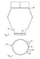
- Fig. 5 illustrates the discharge nozzle 10 of a second embodiment of the 9, the drain pipe 10 has here in its lower end portion has a circumferential groove 30, which at the periphery of the tubular Plug-in area 14 rotates.
- This circumferential groove 30 serves for Receiving an annular clamping element 32. This is in the Fig. 6 illustrated in more detail.
- Fig. 6 shows the top view of the annular clamping element 32 with a plurality of recesses 34 along its circumference.
- the recesses 34 here have a rectangular cross section, so along the circumference of the clamping element 32 outwardly projecting, rectangular Tongues or edges 38 are present, which are the claw portion represent.
- the clamping element 32 has a thickness that is dimensioned such that it is inserted into the circumferential groove 30 of the downcomer 10 according to FIG. 5 can be. For easy insertion into the groove 30, the clamping element 32 at one point of its circumference a transverse, continuous Opening 36.
- the insertion opening 40 is configured such that it includes the insertion area 14 in itself can record. It is tubular to it and its inner diameter is greater than the outer diameter of the tubular insertion region 14, at least in a region from the lower end to over the circumferential groove 30.
- the insertion region 14 of the drain neck 10 and the insertion opening 40 of the drainage pipe bend 12 overlap in an overlapping area 37. This has a width in the axial direction 39.
- the annular clamping element 32 is inserted.
- the edges 38 of the claw portion of the clamping element 32 are above the Diameter of the insertion portion 14 also outwards.
- the claws slightly upwards, d. H. away from the front end of the insertion area 14. They dig into the inner wall of the insertion opening 40 of the drain pipe bow 12.
- the separation of the connector between the drain pipe bend 12 and the drain pipe 10 is therefore due to the Clawing and the bending of the edges 38 upwards only possible with difficulty.
- Fig. 8 shows the partially sectioned side view of the drain neck 10 and of the deferred discharge pipe bend 12 according to a third embodiment of the conduit system according to the invention 9.
- the clamping element is designed as a pin 44, along its longitudinal extension two claw sections in shape having a toothing.
- the gearing can also another Type of surface roughening be provided.
- At any Position on the outer wall of the insertion region 14 has the discharge nozzle 10 an elongated groove 42 which is formed here as a bead.
- the Groove 42 extends in the insertion region 14 advantageously starting from the front end of the downcomer 10 in the axial direction.
- the Groove 42 extends over the front end of the attached drainage pipe bend 12 out.
- Fig. 9A shows the side view of the pin 44 with two along its longitudinal extent extending serrations 50 and 52.
- the pin 44 has a elongated trunk 46 and approximating one from one of its ends orthogonally extending rotary actuator arm 48 so that the pin 44 in about the shape of an upside down L has.
- the trunk 46 has a rectangular cross section.
- the two Claw portions 50, 52 are here on opposite sides arranged the longitudinal extent.
- FIG. 9A shows individual ones along the Longitudinal extension of the trunk 46 with each other arranged Krallzähne 54 the teeth 50 and individual, along the longitudinal extent of the trunk 46th mutually arranged Krallzähne 56 of the teeth 52.
- the teeth 54th and 56 are radially obliquely outward.
- the teeth 54 are axially in the direction the Drehbetutzsarms 48 and the teeth 56 in opposite Oriented towards the lower end of the trunk 46. This can advantageously a particularly strong clamping seat can be achieved.
- the rotary actuation arm 48 has a bend. As a result, he can on the one hand easily by hand grabbed, operated and the pin 44 are twisted. On the other hand lies the Drehbet effet Trentsarm 48, if he twists in the direction of its bending is advantageously direct and close, in the twisted state of trunk 46 on the outside of the attached drainage pipe bend 12 at.
- FIG. 9B shows a further side view rotated by 90 ° with respect to FIG. 9A of the pin 44.
- the teeth 52 with the teeth 56 faces forward.
- the stem 46 has two opposite sides 51 and 53, which are flat and are located between the serrations 54 and 56.
- the insertion of the pin 44 in the groove 42 is advantageously carried out so, that the teeth 50, 52 initially tangentially laterally to the walls of the downcomer 10 and the drainpipe 12 extend.
- the teeth 54, 56 come therefore when pushing not in a significant way with the walls of the two tubular elements 10, 12 in engagement.
- the teeth of a toothing dig into the Wall of a pipe element and the teeth of the other teeth dig in the wall of the other pipe element. This is going to be special easy way a good and firm fit of the pin 44 both in the drain pipe 10 and in the drain pipe 12 guaranteed.
- the pin 44 is in the opposite Direction twisted until again the flat sides 51, 53 the Oppose tubular element walls. Then the pen can easily get out of the Groove 42 removed and the drain pipe bend 12 of the drain pipe 10th to be pulled.
- Fig. 10 is a sectional view of the circumference the downcomer 10 and the drainpipe 12 according to a fourth embodiment of a conduit system 9 according to the invention with two pins 44A and 44B at opposite locations on the circumference of the drain neck 10 shows.
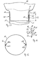
- FIG 11 shows the partially sectioned side view of the drain neck 10 and of the deferred discharge pipe bend 12 according to a fifth embodiment of the conduit system according to the invention.
- the Insertion region 14 of the downcomer 10 and the insertion opening 40 of the Drain pipe elbows 12 overlap in the overlap area 37. This has the width 39 in the axial direction.
- a spring tongue element 62 as a clamping element available.
- FIG. 12 A side view of this spring tongue element 62 is closer in FIG. 12 shown.
- the spring tongue element 62 has a claw portion 66 as outer end, in which the elongated spring tongue element 62 multiple times is angled.
- the claw area 66 angled so that the spring tongue element 62 has a zigzag structure extending in opposite directions one after the other Surveys 80, 82, 84, 86 has.
- the spring tongue element 62 has a hook section 78, which is bent here U-shaped and with it at the front end on a the pipe elements 10, 12 can be plugged.
- the insertion region 14 of the ceremoniesstutzens 10 an elongated groove 57, which is the spring tongue element 62 absorbs.
- the groove 57 extends in the insertion region 14 starting from the front end of the downcomer 10 in the axial direction.
- the Groove 57 has a first deeply cut into the insertion region 14 Nutbe rich 58 and a less deeply in the insertion region 14 cut second groove area 60.
- the claw portion 66 is in the first groove portion 58 inserted.
- the second groove area 60 constitutes a storage area ready, to which the first stretch 76 leans against surface. And the second section 74 leans flat on the transition of the first Nut Schemees 58 to the second groove portion 60 at.
- the hook section 78 is mounted in the frontal end of the downcomer 10.
- the surveys 82 and 86 are supported on the wall of the first groove area 58 of the drain neck 10 and the survey 84 and preferably sharp-edged end of the fifth section 68 on the wall of Insertion opening 40 of the drainpipe 12.
- the spring tongue element 62 in the groove 57 is a particularly good grip the spring tongue element 62 and a particularly good clamping connection given.
- the second groove area 60 not present, so that the area 76 of the clamping element 62 outside rests on the circumference of the insertion region 14.
- Fig. 13 shows a sectional view of the circumference of the downcomer 10 and the drainpipe bend 12 according to a sixth embodiment of the line system 9.
- two spring tongue elements 62A and 62B at opposite locations the scope of the downcomer 10 as clamping elements between the two Pipe elements 10, 12 introduced. This allows the clamping action and the securing of the plug connection between the two tubular elements 10, 12 further increased.
- the grooves are for receiving the clamping elements in the outside of the insertion region 14 of the whilstutzens 10 provided. But it is also possible to have these grooves in to introduce the inside of the insertion opening 40 of the drainage pipe bend 12. Likewise, it is possible that in the previously described with reference to FIGS. 1-4 first embodiment attached to the discharge nozzle 10 Clamping element 17 on the inside of the insertion opening 40 of the drainage pipe bend 12 to install.
Landscapes
- Engineering & Computer Science (AREA)
- General Engineering & Computer Science (AREA)
- Mechanical Engineering (AREA)
- Architecture (AREA)
- Civil Engineering (AREA)
- Structural Engineering (AREA)
- Quick-Acting Or Multi-Walled Pipe Joints (AREA)
- Roof Covering Using Slabs Or Stiff Sheets (AREA)
- Pipeline Systems (AREA)
- Sampling And Sample Adjustment (AREA)
Abstract
Description
- Fig. 1
- ein Anwendungsbeispiel eines erfindungsgemäßen Leitungssystems als Regenfallrohrsystem an einem Haus,
- Fig. 2
- einen Ablaufstutzen eines ersten Ausführungsbeispiels eines erfindungsgemäßen Leitungssystems zum Ableiten von Regenwasser mit einer Zunge als Klemmelement,
- Fig. 3
- eine teilweise geschnittene Seitenansicht des Ablaufstutzens gemäß dem ersten Ausführungsbeispiel,
- Fig. 4
- eine Frontansicht der Zunge gemäß dem ersten Ausführungsbeispiel,
- Fig. 5
- einen Ablaufstutzen eines zweiten Ausführungsbeispiels eines erfindungsgemäßen Leitungssystems zum Ableiten von Regenwasser mit einer Umfangsnut zum Aufnehmen eines ringförmigen Klemmelementes,
- Fig. 6
- eine Draufsicht auf ein Beispiel eines ringförmigen Klemmelementes mit Aussparungen entlang seines Umfangs,
- Fig. 7
- eine teilweise geschnittene Seitenansicht des Ablaufstutzens und eines auf diesen aufgeschobenen Ablaufrohrbogens des Leitungssystems gemäß dem zweiten Ausführungsbeispiel,
- Fig. 8
- eine teilweise geschnittene Seitenansicht eines Ablaufstutzens und eines auf diesen aufgeschobenen Ablaufrohrbogens eines dritten Ausführungsbeispiels eines erfindungsgemäßen Leitungssystems zum Ableiten von Regenwasser mit einem Klemmelement, das als Stift ausgestaltet ist,
- Fig. 9A
- eine Seitenansicht eines Beispiels des Stiftes mit zwei entlang seiner Längserstreckung verlaufenden Zahnungen,
- Fig. 9B
- eine weitere, um 90° gedrehte Seitenansicht des Stiftes gemäß der Fig. 9A,
- Fig. 10
- eine Schnittansicht des Umfangs eines Ablaufstutzens und eines Ablaufrohrbogens eines vierten Ausführungsbeispiels eines erfindungsgemäßen Leitungssystems mit zwei Stiften an gegenüberliegenden Stellen des Umfangs des Ablaufstutzens,
- Fig. 11
- eine teilweise geschnittene Seitenansicht eines Ablaufstutzens und eines auf diesen aufgeschobenen Ablaufrohrbogens eines fünften Ausführungsbeispiels eines erfindungsgemäßen Leitungssystems zum Ableiten von Regenwasser mit einem Federzungenelement als Klemmelement, das eine Zickzackstruktur aufweist,
- Fig. 12
- eine Seitenansicht des Federzungenelementes und
- Fig. 13
- eine Schnittansicht des Umfangs eines Ablaufstutzens und eines Ablaufrohrbogens eines sechsten Ausführungsbeispiels eines erfindungsgemäßen Leitungssystems mit zwei Federzungenelementen an gegenüberliegenden Stellen des Umfangs des Ablaufstutzens.
Claims (23)
- Leitungssystem (9) zum Ableiten von Flüssigkeit; insbesondere Dachentwässerungsrohrsystem, mit wenigstens zwei Rohrelementen (10, 12), die durch Herstellung einer gemeinsamen Steckverbindung aneinander anschließbar sind, wobei eines der Rohrelemente (10) einen als Einsteckbereich (14) vorgesehenen Endabschnitt und das andere Rohrelement (12) einen eine Einstecköffnung (40) zur Aufnahme des Einsteckbereichs (14) aufweisenden Endabschnitt hat,
wobei zur Sicherung der Steckverbindung im betriebsfertig montierten Zustand der Rohrelemente (10, 12) wenigstens ein in deren Überlappungsbereich (37) zwischen den Endabschnitten positioniertes Klemmelement (17, 32, 44, 62), insbesondere aus Metall, vorgesehen ist, dadurch gekennzeichnet, dass das Klemmelement (17, 32, 44, 62) zumindest teilweise in einer insbesondere als Sicke ausgebildeten Nut (16, 30, 42, 57) in dem Endabschnitt (14, 40) eines der Rohrelemente (10, 12) aufgenommen ist. - Leitungssystem nach Anspruch 1, dadurch gekennzeichnet, dass das Klemmelement (17, 32, 44, 62) wenigstens einen insbesondere scharfkantigen Krallenabschnitt (20, 50, 52, 66) aufweist, mit dem es sich in Richtung aus der Nut (16, 30, 42, 57) des einen Rohrelements heraus nach außen erstreckt, derart, dass der Krallenabschnitt (20, 50, 52, 66) mit dem betreffenden anderen Rohrelement (10, 12) an dessen Endabschnitt (14, 40) verkrallend in Eingriff kommen kann, um einer Trennbewegung der Rohrelemente (10, 12) relativ zueinander entgegenzuwirken.
- Leitungssystem nach Anspruch 1 oder 2, dadurch gekennzeichnet, dass das Klemmelement (17, 32, 44, 62) so gestaltet und zwischen den Endabschnitten (14, 40) positioniert ist, dass es beim Zusammenstecken der Rohrelemente (10, 12) einen geringeren Klemmwiderstand erzeugt als beim Auseinanderziehen der Rohrelemente (10, 12).
- Leitungssystem nach Anspruch 1, 2 oder 3, dadurch gekennzeichnet, dass das Klemmelement (17) an einem der Rohrelemente (10) formschlüssig fixiert, insbesondere angenietet ist.
- Leitungssystem nach Anspruch 4, dadurch gekennzeichnet, dass der Krallenabschnitt (20, 50, 52, 66) vor dem Zusammenstecken der Rohrelemente (10, 12) orthogonal zur Rohrelementachse oder schräg dazu in axialer Richtung weg von dem stirnseitigen Ende des die Nut (16, 30, 42, 57) mit dem darin aufgenommenen Klemmelement (17, 32, 44, 62) aufweisenden Endabschnittes (14) des einen Rohrelementes (10) orientiert ist, so dass er beim Zusammenstecken der Rohrelemente (10, 12) von dem betreffenden anderen Rohrelement (12) unter Aufrechterhaltung der gegenseitigen Beaufschlagung zwischen dem Krallenabschnitt (20, 50, 52, 66) und dem anderen Rohrelement (12) zumindest teilweise in die Nut (16, 30, 42, 57) und dabei axial in Richtung weg von dem stirnseitigen Ende des die Nut (16, 30, 42, 57) aufweisenden Endabschnittes (14) des einen Rohrelementes (10) verdrängt werden kann.
- Leitungssystem nach einem der vorhergehenden Ansprüche, dadurch gekennzeichnet, dass der Krallenabschnitt (20, 50, 52) verzahnt ist.
- Leitungssystem nach einem der vorhergehenden Ansprüche, dadurch gekennzeichnet, dass das Klemmelement wenigstens eine Zunge (17) mit einem Krallenabschnitt (20) an einem ihrer Enden aufweist.
- Leitungssystem nach Anspruch 7, dadurch gekennzeichnet, dass die Zunge (17) insbesondere mehrfach abgewinkelt ist.
- Leitungssystem nach einem der vorhergehenden Ansprüche, dadurch gekennzeichnet, dass das Klemmelement als insbesondere unterbrochenes Ringelement (32) ausgebildet ist.
- Leitungssystem nach Anspruch 9, dadurch gekennzeichnet, dass das Ringelement (32) in einer am Umfang eines der Rohrelemente (10) umlaufenden Nut (30) aufgenommen ist, so dass der Krallenabschnitt vor dem Zusammenstecken der Rohrelemente (10, 12) radial aus der Nut (30) absteht.
- Leitungssystem nach Anspruch 1, dadurch gekennzeichnet, dass das Klemmelement ein Stift (44) ist, der entlang seiner Längserstreckung wenigstens einen Krallenabschnitt (50, 52) in Form einer Verzahnung oder sonstigen Oberflächenaufrauung aufweist.
- Leitungssystem nach Anspruch 11, dadurch gekennzeichnet, dass der Stift (44) an zwei einander gegenüberliegenden Seiten des Stiftes mit einem jeweiligen Krallenabschnitt (50, 52) versehen ist.
- Leitungssystem nach Anspruch 12, dadurch gekennzeichnet, dass die Krallenabschnitte (50, 52) Verzahnungen mit axial und radial schräg nach außen abstehenden Krallzähnen (54, 56) aufweisen, wobei die Zähne (54, 56) des einen Krallenabschnittes (50, 52) in axialer Richtung des Stiftes (44) entgegengesetzt zu den Zähnen (54, 56) des anderen Krallenabschnittes (50, 52) orientiert sind.
- Leitungssystem nach einem der Ansprüche 11 bis 13, dadurch gekennzeichnet, dass wenigstens eines der Rohrelemente (10) eine vom stirnseitigen Ende seines Endabschnittes ausgehende Nut (42), insbesondere Sicke, zur Aufnahme des Stiftes (44) aufweist.
- Leitungssystem nach Anspruch 14, dadurch gekennzeichnet, dass der Stift (44) in der Nut (42) um seine Längsachse verdrehbar ist, um den jeweiligen Krallenabschnitt (50, 52) mit einem betreffenden Rohrelementendabschnitt (14, 40) verkrallend in Eingriff oder außer Eingriff bringen zu können.
- Leitungssystem nach Anspruch 15, dadurch gekennzeichnet, dass der Stift (44) an einem axialen Ende einen seitlich abstehenden Drehbetätigungsarm (48) aufweist.
- Leitungssystem nach einem der vorhergehenden Ansprüche, gekennzeichnet durch ein als Federzungenelement (62) ausgebildetes Klemmelement, welches in einem den Krallenabschnitt (66) als äußeres Ende aufweisenden Bereich mehrfach abgewinkelt ist, wobei der mehrfach abgewinkelte Bereich (66) im betriebsfertig montierten Zustand der Rohrelemente (10, 12) in einer Nut (57) des Endabschnittes (14) eines der Rohrelemente (10) aufgenommen ist und sich mit dem Krallenabschnitt (66) an dem anderen Rohrelement abstützt.
- Leitungssystem nach Anspruch 17, dadurch gekennzeichnet, dass das Federzungenelement (62) an seinem von dem Krallenabschnitt (66) entfernten Ende einen Hakenabschnitt (78) aufweist, mit dem es am stirnseitigen Ende des die Nut (57) aufweisenden Endabschnittes (14) des einen Rohrelementes (10) auf dieses Rohrelement (10) aufsteckbar ist.
- Leitungssystem nach Anspruch 18, dadurch gekennzeichnet, dass der mehrfach abgewinkelte Bereich (66) eine Zickzackstruktur aufweist und sich im betriebsfertig montierten Zustand der Rohrelemente (10, 12) mit den aufeinander folgend in entgegengesetzte Richtungen erstreckenden Erhebungen (80, 82, 84, 86) der Zickzackstruktur an den einander radial überlappenden Endabschnitten (14, 40) der Rohrelemente (10, 12) abstützt.
- Leitungssystem nach einem der vorhergehenden Ansprüche, dadurch gekennzeichnet, dass die Rohrelemente (10, 12) aus Metall, insbesondere Edelstahl oder einer Kupferlegierung, gebildet sind.
- Leitungssystem nach einem der vorhergehenden Ansprüche, dadurch gekennzeichnet, dass das Klemmelement (17, 32, 44, 62) aus einem Stahl, insbesondere aus gehärtetem Stahl, gebildet ist.
- Leitungssystem nach einem der vorhergehenden Ansprüche, dadurch gekennzeichnet, dass es ein Leitungssystem (9) zum Ableiten von Regenwasser ist und das erste Rohrelement (10) ein Ablaufstutzen zum Anbringen an ein Dachrinnenelement (7) und das zweite Rohrelement (12) ein Ablaufrohrbogen ist.
- Leitungssystem nach Anspruch 22, dadurch gekennzeichnet, dass das Klemmelement (17) an dem Ablaufstutzen (10) fixiert ist.
Applications Claiming Priority (2)
| Application Number | Priority Date | Filing Date | Title |
|---|---|---|---|
| DE10353660A DE10353660A1 (de) | 2003-11-17 | 2003-11-17 | Leitungssystem zum Ableiten von Flüssigkeit |
| DE10353660 | 2003-11-17 |
Publications (3)
| Publication Number | Publication Date |
|---|---|
| EP1531208A2 true EP1531208A2 (de) | 2005-05-18 |
| EP1531208A3 EP1531208A3 (de) | 2005-06-08 |
| EP1531208B1 EP1531208B1 (de) | 2007-04-25 |
Family
ID=34428770
Family Applications (1)
| Application Number | Title | Priority Date | Filing Date |
|---|---|---|---|
| EP04025417A Expired - Lifetime EP1531208B1 (de) | 2003-11-17 | 2004-10-26 | Leitungssystem zum Ableiten von Flüssigkeit |
Country Status (3)
| Country | Link |
|---|---|
| EP (1) | EP1531208B1 (de) |
| AT (1) | ATE360733T1 (de) |
| DE (2) | DE10353660A1 (de) |
Cited By (3)
| Publication number | Priority date | Publication date | Assignee | Title |
|---|---|---|---|---|
| EP1722145A3 (de) * | 2005-05-13 | 2010-03-17 | Metallwarenfabrik Marktoberdorf GmbH & Co. KG | Rohrelement mit Schutzelement |
| EP2626610B1 (de) * | 2012-02-10 | 2015-08-26 | eka edelstahlkamine gmbh | Vorrichtung zum Verbinden von Rohrabschnitten |
| EP3524749A1 (de) * | 2018-02-09 | 2019-08-14 | Metallwarenfabrik Marktoberdorf GmbH & Co. KG | Klemmfeder zur verbindung von entwässerungskomponenten, insbesondere dachentwässerungskomponenten |
Citations (1)
| Publication number | Priority date | Publication date | Assignee | Title |
|---|---|---|---|---|
| DE10160194A1 (de) | 2001-12-09 | 2003-06-18 | Zambelli Fertigungs Gmbh | Montagehilfe für Regenwasser-Ablaufgarnituren |
Family Cites Families (14)
| Publication number | Priority date | Publication date | Assignee | Title |
|---|---|---|---|---|
| US1686254A (en) * | 1927-01-19 | 1928-10-02 | Rachlin Max | Sheet-metal pipe coupling |
| US2127284A (en) * | 1937-01-18 | 1938-08-16 | William S Board | Pipe coupling |
| US2212679A (en) * | 1937-09-27 | 1940-08-27 | Hoover Co | Dusting tool for suction cleaners |
| GB631745A (en) * | 1946-12-11 | 1949-11-09 | Ernest William Poole Lines | An improved tube joint |
| DE3322202C2 (de) * | 1983-06-21 | 1986-11-20 | Helmut 7518 Bretten Hackel | Vorrichtung zum Montieren oder Lösen einer kraft- und formschlüssigen Rohr-Steckverbindung |
| DE3602658C2 (de) * | 1986-01-29 | 1994-09-08 | Franz Zambelli | Dachrinnenablaufstutzen |
| JP2767613B2 (ja) * | 1989-07-07 | 1998-06-18 | 臼井国際産業株式会社 | 細径配管接続用コネクター |
| EP0797038A1 (de) * | 1996-03-20 | 1997-09-24 | Climovent System s.a.s. di Franco Guazzone e C | Rohrfitting, speziell für Lüftungssysteme |
| US6168208B1 (en) * | 1998-05-27 | 2001-01-02 | Ken Thaler | Seal for use with roof drains |
| US6341804B1 (en) * | 1998-11-20 | 2002-01-29 | Tosetz Co., Ltd | Slip-out preventive unit of supply exhaust pipe |
| DE19939398A1 (de) * | 1999-08-19 | 2001-03-08 | Waldsassen Ziegelwerk Ag | Muffenrohranordnung für eine Abgasleitung und Zentriervorrichtung hierfür |
| GB0015867D0 (en) * | 2000-06-28 | 2000-08-23 | Pegler Limited | Tube coupling |
| DE20013515U1 (de) * | 2000-08-05 | 2000-10-19 | Rheinzink GmbH & Co. KG, 45711 Datteln | Anschluß für einen Dachrinnenentwässerungsstrang an eine Dachrinne an einem Dachüberstand und Bau-Set dazu |
| US7121593B2 (en) * | 2001-01-19 | 2006-10-17 | Victaulic Company | Triple-expanded mechanical pipe coupling derived from a standard fitting |
-
2003
- 2003-11-17 DE DE10353660A patent/DE10353660A1/de not_active Withdrawn
-
2004
- 2004-10-26 EP EP04025417A patent/EP1531208B1/de not_active Expired - Lifetime
- 2004-10-26 DE DE502004003594T patent/DE502004003594D1/de not_active Expired - Lifetime
- 2004-10-26 AT AT04025417T patent/ATE360733T1/de active
Patent Citations (1)
| Publication number | Priority date | Publication date | Assignee | Title |
|---|---|---|---|---|
| DE10160194A1 (de) | 2001-12-09 | 2003-06-18 | Zambelli Fertigungs Gmbh | Montagehilfe für Regenwasser-Ablaufgarnituren |
Cited By (3)
| Publication number | Priority date | Publication date | Assignee | Title |
|---|---|---|---|---|
| EP1722145A3 (de) * | 2005-05-13 | 2010-03-17 | Metallwarenfabrik Marktoberdorf GmbH & Co. KG | Rohrelement mit Schutzelement |
| EP2626610B1 (de) * | 2012-02-10 | 2015-08-26 | eka edelstahlkamine gmbh | Vorrichtung zum Verbinden von Rohrabschnitten |
| EP3524749A1 (de) * | 2018-02-09 | 2019-08-14 | Metallwarenfabrik Marktoberdorf GmbH & Co. KG | Klemmfeder zur verbindung von entwässerungskomponenten, insbesondere dachentwässerungskomponenten |
Also Published As
| Publication number | Publication date |
|---|---|
| ATE360733T1 (de) | 2007-05-15 |
| EP1531208A3 (de) | 2005-06-08 |
| DE502004003594D1 (de) | 2007-06-06 |
| EP1531208B1 (de) | 2007-04-25 |
| DE10353660A1 (de) | 2005-06-23 |
Similar Documents
| Publication | Publication Date | Title |
|---|---|---|
| DE2828893C2 (de) | Rohrverbinder für Kabelschutzrohre | |
| DE19841643B4 (de) | Kabelrinne aus Blech | |
| DE3617911A1 (de) | Befestigungselement zur halterung von rohren unterschiedlichen durchmessers | |
| CH634136A5 (de) | Rohrschelle. | |
| EP2054558A1 (de) | Entwässerungsvorrichtung | |
| DE202005001715U1 (de) | Flanschverbindung für Leitungen | |
| WO2013050168A1 (de) | Photovoltaikgestell, pfettenbaugruppe und verbindungsteil | |
| DE69908576T2 (de) | Verbindungsvorrichtung | |
| DE202016105953U1 (de) | Einfassung von Rasenflächen und Beeten | |
| DE8032468U1 (de) | Aufnahmeelement zur rasch kuppelnden verbindung von schlaeuchen | |
| DE3235624C2 (de) | Manschettenförmige Rohrleitungskupplung | |
| EP1531208A2 (de) | Leitungssystem zum Ableiten von Flüssigkeit | |
| DE202010007139U1 (de) | Vorrichtung zur Befestigung eines Moduls zur Nutzung von Sonnenenergie | |
| EP1457607B1 (de) | Sanitärarmatur mit einer Einrichtung zum Befestigen einer Leitung | |
| EP3583664A1 (de) | Knickschutz für konfektionierte kabel | |
| EP0407352A2 (de) | Vorrichtung zur Befestigung eines Montagerahmens für Sanitärapparate | |
| EP2369215A1 (de) | Steckverbindung | |
| DE19836226C2 (de) | Vorrichtung zum Verbinden von zwei Profilschienen | |
| EP1490620B1 (de) | Verbindungsstück für ein rohrleitungsnetz | |
| DE19621098C2 (de) | Gelenkverbindung | |
| DE102012223075B4 (de) | Verbindungssystem für ein Tragwerk | |
| EP1157625B1 (de) | Kettenglied für eine Schmuckkette | |
| DE102008037961B4 (de) | Schellenverschluss für eine Rohrschelle | |
| DE8419094U1 (de) | Rohreinsatz in elementbauweise | |
| DE19651168C2 (de) | Rastvorrichtung für eine Steckkupplung zum Ankuppeln eines Schlauches in einen Rohrstutzen |
Legal Events
| Date | Code | Title | Description |
|---|---|---|---|
| PUAI | Public reference made under article 153(3) epc to a published international application that has entered the european phase |
Free format text: ORIGINAL CODE: 0009012 |
|
| PUAL | Search report despatched |
Free format text: ORIGINAL CODE: 0009013 |
|
| AK | Designated contracting states |
Kind code of ref document: A2 Designated state(s): AT BE BG CH CY CZ DE DK EE ES FI FR GB GR HU IE IT LI LU MC NL PL PT RO SE SI SK TR |
|
| AX | Request for extension of the european patent |
Extension state: AL HR LT LV MK |
|
| AK | Designated contracting states |
Kind code of ref document: A3 Designated state(s): AT BE BG CH CY CZ DE DK EE ES FI FR GB GR HU IE IT LI LU MC NL PL PT RO SE SI SK TR |
|
| AX | Request for extension of the european patent |
Extension state: AL HR LT LV MK |
|
| RIC1 | Information provided on ipc code assigned before grant |
Ipc: 7F 16L 37/12 B Ipc: 7F 16L 37/084 B Ipc: 7F 16L 37/14 B Ipc: 7F 16L 37/15 B Ipc: 7F 16L 37/091 B Ipc: 7E 04D 13/08 A |
|
| 17P | Request for examination filed |
Effective date: 20050713 |
|
| AKX | Designation fees paid |
Designated state(s): AT BE BG CH CY CZ DE DK EE ES FI FR GB GR HU IE IT LI LU MC NL PL PT RO SE SI SK TR |
|
| AXX | Extension fees paid |
Extension state: MK Payment date: 20050713 Extension state: LV Payment date: 20050713 Extension state: LT Payment date: 20050713 Extension state: HR Payment date: 20050713 Extension state: AL Payment date: 20050713 |
|
| GRAP | Despatch of communication of intention to grant a patent |
Free format text: ORIGINAL CODE: EPIDOSNIGR1 |
|
| GRAS | Grant fee paid |
Free format text: ORIGINAL CODE: EPIDOSNIGR3 |
|
| GRAA | (expected) grant |
Free format text: ORIGINAL CODE: 0009210 |
|
| AK | Designated contracting states |
Kind code of ref document: B1 Designated state(s): AT BE BG CH CY CZ DE DK EE ES FI FR GB GR HU IE IT LI LU MC NL PL PT RO SE SI SK TR |
|
| AX | Request for extension of the european patent |
Extension state: AL HR LT LV MK |
|
| PG25 | Lapsed in a contracting state [announced via postgrant information from national office to epo] |
Ref country code: FI Free format text: LAPSE BECAUSE OF FAILURE TO SUBMIT A TRANSLATION OF THE DESCRIPTION OR TO PAY THE FEE WITHIN THE PRESCRIBED TIME-LIMIT Effective date: 20070425 |
|
| REG | Reference to a national code |
Ref country code: GB Ref legal event code: FG4D Free format text: NOT ENGLISH |
|
| REG | Reference to a national code |
Ref country code: IE Ref legal event code: FG4D Free format text: LANGUAGE OF EP DOCUMENT: GERMAN |
|
| REG | Reference to a national code |
Ref country code: CH Ref legal event code: EP |
|
| REF | Corresponds to: |
Ref document number: 502004003594 Country of ref document: DE Date of ref document: 20070606 Kind code of ref document: P |
|
| REG | Reference to a national code |
Ref country code: DE Ref legal event code: R096 Ref document number: 502004003594 Country of ref document: DE Effective date: 20070606 |
|
| PG25 | Lapsed in a contracting state [announced via postgrant information from national office to epo] |
Ref country code: SE Free format text: LAPSE BECAUSE OF FAILURE TO SUBMIT A TRANSLATION OF THE DESCRIPTION OR TO PAY THE FEE WITHIN THE PRESCRIBED TIME-LIMIT Effective date: 20070725 |
|
| PG25 | Lapsed in a contracting state [announced via postgrant information from national office to epo] |
Ref country code: ES Free format text: LAPSE BECAUSE OF FAILURE TO SUBMIT A TRANSLATION OF THE DESCRIPTION OR TO PAY THE FEE WITHIN THE PRESCRIBED TIME-LIMIT Effective date: 20070805 |
|
| PG25 | Lapsed in a contracting state [announced via postgrant information from national office to epo] |
Ref country code: PT Free format text: LAPSE BECAUSE OF FAILURE TO SUBMIT A TRANSLATION OF THE DESCRIPTION OR TO PAY THE FEE WITHIN THE PRESCRIBED TIME-LIMIT Effective date: 20070925 |
|
| LTIE | Lt: invalidation of european patent or patent extension |
Effective date: 20070425 |
|
| NLV1 | Nl: lapsed or annulled due to failure to fulfill the requirements of art. 29p and 29m of the patents act | ||
| GBV | Gb: ep patent (uk) treated as always having been void in accordance with gb section 77(7)/1977 [no translation filed] |
Effective date: 20070425 |
|
| PG25 | Lapsed in a contracting state [announced via postgrant information from national office to epo] |
Ref country code: PL Free format text: LAPSE BECAUSE OF FAILURE TO SUBMIT A TRANSLATION OF THE DESCRIPTION OR TO PAY THE FEE WITHIN THE PRESCRIBED TIME-LIMIT Effective date: 20070425 |
|
| REG | Reference to a national code |
Ref country code: IE Ref legal event code: FD4D |
|
| EN | Fr: translation not filed | ||
| PG25 | Lapsed in a contracting state [announced via postgrant information from national office to epo] |
Ref country code: SI Free format text: LAPSE BECAUSE OF FAILURE TO SUBMIT A TRANSLATION OF THE DESCRIPTION OR TO PAY THE FEE WITHIN THE PRESCRIBED TIME-LIMIT Effective date: 20070425 Ref country code: NL Free format text: LAPSE BECAUSE OF FAILURE TO SUBMIT A TRANSLATION OF THE DESCRIPTION OR TO PAY THE FEE WITHIN THE PRESCRIBED TIME-LIMIT Effective date: 20070425 Ref country code: IE Free format text: LAPSE BECAUSE OF FAILURE TO SUBMIT A TRANSLATION OF THE DESCRIPTION OR TO PAY THE FEE WITHIN THE PRESCRIBED TIME-LIMIT Effective date: 20070425 Ref country code: DK Free format text: LAPSE BECAUSE OF FAILURE TO SUBMIT A TRANSLATION OF THE DESCRIPTION OR TO PAY THE FEE WITHIN THE PRESCRIBED TIME-LIMIT Effective date: 20070425 Ref country code: CZ Free format text: LAPSE BECAUSE OF FAILURE TO SUBMIT A TRANSLATION OF THE DESCRIPTION OR TO PAY THE FEE WITHIN THE PRESCRIBED TIME-LIMIT Effective date: 20070425 Ref country code: BG Free format text: LAPSE BECAUSE OF FAILURE TO SUBMIT A TRANSLATION OF THE DESCRIPTION OR TO PAY THE FEE WITHIN THE PRESCRIBED TIME-LIMIT Effective date: 20070725 |
|
| PG25 | Lapsed in a contracting state [announced via postgrant information from national office to epo] |
Ref country code: SK Free format text: LAPSE BECAUSE OF FAILURE TO SUBMIT A TRANSLATION OF THE DESCRIPTION OR TO PAY THE FEE WITHIN THE PRESCRIBED TIME-LIMIT Effective date: 20070425 |
|
| PLBE | No opposition filed within time limit |
Free format text: ORIGINAL CODE: 0009261 |
|
| STAA | Information on the status of an ep patent application or granted ep patent |
Free format text: STATUS: NO OPPOSITION FILED WITHIN TIME LIMIT |
|
| 26N | No opposition filed |
Effective date: 20080128 |
|
| BERE | Be: lapsed |
Owner name: METALLWARENFABRIK MARKTOBERDORF G.M.B.H. & CO. KG Effective date: 20071031 |
|
| PG25 | Lapsed in a contracting state [announced via postgrant information from national office to epo] |
Ref country code: IT Free format text: LAPSE BECAUSE OF FAILURE TO SUBMIT A TRANSLATION OF THE DESCRIPTION OR TO PAY THE FEE WITHIN THE PRESCRIBED TIME-LIMIT Effective date: 20070425 Ref country code: GR Free format text: LAPSE BECAUSE OF FAILURE TO SUBMIT A TRANSLATION OF THE DESCRIPTION OR TO PAY THE FEE WITHIN THE PRESCRIBED TIME-LIMIT Effective date: 20070726 Ref country code: GB Free format text: LAPSE BECAUSE OF FAILURE TO SUBMIT A TRANSLATION OF THE DESCRIPTION OR TO PAY THE FEE WITHIN THE PRESCRIBED TIME-LIMIT Effective date: 20070425 Ref country code: FR Free format text: LAPSE BECAUSE OF FAILURE TO SUBMIT A TRANSLATION OF THE DESCRIPTION OR TO PAY THE FEE WITHIN THE PRESCRIBED TIME-LIMIT Effective date: 20071221 |
|
| REG | Reference to a national code |
Ref country code: DE Ref legal event code: R097 Ref document number: 502004003594 Country of ref document: DE Effective date: 20080128 |
|
| PG25 | Lapsed in a contracting state [announced via postgrant information from national office to epo] |
Ref country code: RO Free format text: LAPSE BECAUSE OF FAILURE TO SUBMIT A TRANSLATION OF THE DESCRIPTION OR TO PAY THE FEE WITHIN THE PRESCRIBED TIME-LIMIT Effective date: 20070425 Ref country code: MC Free format text: LAPSE BECAUSE OF NON-PAYMENT OF DUE FEES Effective date: 20071031 |
|
| PG25 | Lapsed in a contracting state [announced via postgrant information from national office to epo] |
Ref country code: BE Free format text: LAPSE BECAUSE OF NON-PAYMENT OF DUE FEES Effective date: 20071031 |
|
| PG25 | Lapsed in a contracting state [announced via postgrant information from national office to epo] |
Ref country code: FR Free format text: LAPSE BECAUSE OF FAILURE TO SUBMIT A TRANSLATION OF THE DESCRIPTION OR TO PAY THE FEE WITHIN THE PRESCRIBED TIME-LIMIT Effective date: 20070425 |
|
| PG25 | Lapsed in a contracting state [announced via postgrant information from national office to epo] |
Ref country code: EE Free format text: LAPSE BECAUSE OF FAILURE TO SUBMIT A TRANSLATION OF THE DESCRIPTION OR TO PAY THE FEE WITHIN THE PRESCRIBED TIME-LIMIT Effective date: 20070425 |
|
| REG | Reference to a national code |
Ref country code: CH Ref legal event code: PL |
|
| PG25 | Lapsed in a contracting state [announced via postgrant information from national office to epo] |
Ref country code: CY Free format text: LAPSE BECAUSE OF FAILURE TO SUBMIT A TRANSLATION OF THE DESCRIPTION OR TO PAY THE FEE WITHIN THE PRESCRIBED TIME-LIMIT Effective date: 20070425 |
|
| PG25 | Lapsed in a contracting state [announced via postgrant information from national office to epo] |
Ref country code: LU Free format text: LAPSE BECAUSE OF NON-PAYMENT OF DUE FEES Effective date: 20071026 |
|
| PG25 | Lapsed in a contracting state [announced via postgrant information from national office to epo] |
Ref country code: HU Free format text: LAPSE BECAUSE OF FAILURE TO SUBMIT A TRANSLATION OF THE DESCRIPTION OR TO PAY THE FEE WITHIN THE PRESCRIBED TIME-LIMIT Effective date: 20071026 Ref country code: TR Free format text: LAPSE BECAUSE OF FAILURE TO SUBMIT A TRANSLATION OF THE DESCRIPTION OR TO PAY THE FEE WITHIN THE PRESCRIBED TIME-LIMIT Effective date: 20070425 |
|
| PG25 | Lapsed in a contracting state [announced via postgrant information from national office to epo] |
Ref country code: LI Free format text: LAPSE BECAUSE OF NON-PAYMENT OF DUE FEES Effective date: 20081031 Ref country code: CH Free format text: LAPSE BECAUSE OF NON-PAYMENT OF DUE FEES Effective date: 20081031 |
|
| REG | Reference to a national code |
Ref country code: DE Ref legal event code: R082 Ref document number: 502004003594 Country of ref document: DE Representative=s name: DR. WEITZEL & PARTNER PATENT- UND RECHTSANWAEL, DE |
|
| PGFP | Annual fee paid to national office [announced via postgrant information from national office to epo] |
Ref country code: AT Payment date: 20210811 Year of fee payment: 18 Ref country code: DE Payment date: 20211104 Year of fee payment: 18 |
|
| REG | Reference to a national code |
Ref country code: DE Ref legal event code: R081 Ref document number: 502004003594 Country of ref document: DE Owner name: ROESLE GROUP GMBH, DE Free format text: FORMER OWNER: METALLWARENFABRIK MARKTOBERDORF GMBH & CO. KG, 87616 MARKTOBERDORF, DE |
|
| REG | Reference to a national code |
Ref country code: AT Ref legal event code: PC Ref document number: 360733 Country of ref document: AT Kind code of ref document: T Owner name: ROESLE GROUP GMBH, DE Effective date: 20220419 |
|
| REG | Reference to a national code |
Ref country code: DE Ref legal event code: R119 Ref document number: 502004003594 Country of ref document: DE |
|
| REG | Reference to a national code |
Ref country code: AT Ref legal event code: MM01 Ref document number: 360733 Country of ref document: AT Kind code of ref document: T Effective date: 20221026 |
|
| P01 | Opt-out of the competence of the unified patent court (upc) registered |
Effective date: 20230512 |
|
| PG25 | Lapsed in a contracting state [announced via postgrant information from national office to epo] |
Ref country code: DE Free format text: LAPSE BECAUSE OF NON-PAYMENT OF DUE FEES Effective date: 20230503 Ref country code: AT Free format text: LAPSE BECAUSE OF NON-PAYMENT OF DUE FEES Effective date: 20221026 |