EP1532016B1 - Procede pour remplir au moins deux contenants et circuit pneumatique permettant de mettre en oeuvre ce procede - Google Patents
Procede pour remplir au moins deux contenants et circuit pneumatique permettant de mettre en oeuvre ce procede Download PDFInfo
- Publication number
- EP1532016B1 EP1532016B1 EP03790652A EP03790652A EP1532016B1 EP 1532016 B1 EP1532016 B1 EP 1532016B1 EP 03790652 A EP03790652 A EP 03790652A EP 03790652 A EP03790652 A EP 03790652A EP 1532016 B1 EP1532016 B1 EP 1532016B1
- Authority
- EP
- European Patent Office
- Prior art keywords
- feed pump
- receptacle
- working fluid
- pressure
- receptacles
- Prior art date
- Legal status (The legal status is an assumption and is not a legal conclusion. Google has not performed a legal analysis and makes no representation as to the accuracy of the status listed.)
- Expired - Lifetime
Links
- 238000000034 method Methods 0.000 title claims description 36
- 239000012530 fluid Substances 0.000 claims description 42
- 230000001105 regulatory effect Effects 0.000 claims description 5
- 230000000694 effects Effects 0.000 description 11
- 239000012528 membrane Substances 0.000 description 3
- 238000009423 ventilation Methods 0.000 description 3
- 238000013022 venting Methods 0.000 description 3
- 230000001276 controlling effect Effects 0.000 description 2
- 230000001419 dependent effect Effects 0.000 description 2
- 230000007613 environmental effect Effects 0.000 description 2
- 239000007788 liquid Substances 0.000 description 2
- 238000005086 pumping Methods 0.000 description 2
- 230000001133 acceleration Effects 0.000 description 1
- 230000003213 activating effect Effects 0.000 description 1
- 238000013461 design Methods 0.000 description 1
- 238000011161 development Methods 0.000 description 1
- 230000018109 developmental process Effects 0.000 description 1
- 238000000605 extraction Methods 0.000 description 1
- 230000007794 irritation Effects 0.000 description 1
- 230000035515 penetration Effects 0.000 description 1
- 238000012545 processing Methods 0.000 description 1
- 230000000630 rising effect Effects 0.000 description 1
- 238000011144 upstream manufacturing Methods 0.000 description 1
- XLYOFNOQVPJJNP-UHFFFAOYSA-N water Substances O XLYOFNOQVPJJNP-UHFFFAOYSA-N 0.000 description 1
Images


Classifications
-
- B—PERFORMING OPERATIONS; TRANSPORTING
- B60—VEHICLES IN GENERAL
- B60N—SEATS SPECIALLY ADAPTED FOR VEHICLES; VEHICLE PASSENGER ACCOMMODATION NOT OTHERWISE PROVIDED FOR
- B60N2/00—Seats specially adapted for vehicles; Arrangement or mounting of seats in vehicles
- B60N2/90—Details or parts not otherwise provided for
- B60N2/914—Hydro-pneumatic adjustments of the shape
-
- B—PERFORMING OPERATIONS; TRANSPORTING
- B60—VEHICLES IN GENERAL
- B60N—SEATS SPECIALLY ADAPTED FOR VEHICLES; VEHICLE PASSENGER ACCOMMODATION NOT OTHERWISE PROVIDED FOR
- B60N2/00—Seats specially adapted for vehicles; Arrangement or mounting of seats in vehicles
- B60N2/90—Details or parts not otherwise provided for
- B60N2/976—Details or parts not otherwise provided for massaging systems
Definitions
- the invention relates to a method for alternately pressurizing at least two recipients of a pneumatic system, for example a massage system of a motor vehicle seat with a pressure medium flow. Furthermore, the invention relates to a pneumatic circuit for carrying out this method.
- Pneumatic control and regulation circuits are used in a variety of technical applications.
- pneumatic methods and corresponding pneumatic circuits are used, for example, to adapt the otherwise standardized contour of the vehicle seats to external influences or to the individual wishes of the motor vehicle user.
- a pneumatically controlled seat for a vehicle which makes it possible to vary the pressure distribution of the seat for the driver.
- This device comprises a plurality of integrated in the seat of the vehicle, flexible air chambers, which are connected via a corresponding number of connecting means with an air pump and a pressure sensor.
- Each connecting means has a valve, which can be controlled by electronic control means, which evaluate the signal of the pressure sensor.
- the combined, pneumatic and electrical circuit of this device allows the plurality of valves to build defined pressures in the individual air chambers of the seat and so, both to increase the comfort of the seat, and to take into account longitudinal or lateral accelerations of the vehicle.
- the device allows the US 4,655,505 to continuously vary the pressure in each individual air chamber, so that an optimized pressure distribution is adjustable or the driver experiences a massage effect by an oscillating change in the pressure conditions in the air chambers.
- the GB-A-2144984 discloses a method and a pneumatic circuit according to the preamble of claims 1 and 10.
- Object of the present invention is to realize a method or a pneumatic circuit for alternately pressurizing at least two recipients of a pneumatic system with a pressure medium flow, which allows a simple but reliable way, the adequate filling of the recipients involved.
- the inventive method for alternately pressurizing at least two receivers of a pneumatic system, in particular a pneumatic massage system for a motor vehicle seat, with a pressure medium flow or the corresponding pneumatic circuit provides that at least serving as a recipient first air cushion is filled with a gaseous working fluid, while the working fluid is actively removed from at least one further, second air cushion.
- the method according to the invention or the pneumatic circuit for carrying out this method improves the operation of, for example, a ventilation chamber-driven massage system in a vehicle seat, in which the passive ventilation of the cushions according to the prior art is replaced by an active ventilation. Passive venting is highly dependent on environmental conditions (eg seat design, rider weight, ambient temperature, ). With an active evacuation of the pillows involved, the achievable massage effect becomes more noticeable.
- a cushion In a seat massage system, which consists of at least two air cushions, which are installed in a vehicle seat, a cushion is alternately filled with air or other type, gaseous working fluid and in the other cushion, the air is actively sucked. Through this extraction of air, the corresponding pillow is better emptied and thus the massage effect, which is dependent on the pressure difference in the air cushion involved, reinforced.
- the pressure in the at least one air cushion to be emptied can be used to fill the at least one air cushion to be filled.
- air cushion is not limited to the use of air as the working fluid of the pneumatic system.
- the term “pillow” is to be understood in a broader sense and is intended to include at least one inflatable recipient.
- Such a pneumatic system can be realized with a whole series of gaseous working fluids. By actively draining the one air bag, the pressure in the pad to be dumped can be used to fill another pad rather than escape into the environment as in the corresponding prior art systems. This essentially closed working group means an improvement in the efficiency of the pneumatic system and an energy saving in the operation of such a system.
- the mutual filling of the air cushion is achieved by reversing the direction of rotation of the pumping the working fluid.
- the use of such a pump makes it possible, in a very simple way, to fill or empty the airbags involved alternately.
- Such a pump is driven in an advantageous manner by an electric motor whose speed and direction of rotation can be predetermined, for example via a corresponding control unit.
- a pneumatic system in which the final pressure in the recipient to be filled (air cushion), or the frequency of the alternating admission of the recipients involved with a pressure medium flow, can be predetermined.
- the final pressure in the pillow to be filled which determines the hardness of the vehicle seat and determines the strength of the massage effect, for example, be manually specified via corresponding controls.
- the desired End pressure in the air cushion for example, the frequency with which the air bags are filled and emptied manually adjusted and thus adapted to the individual driving situation.
- the filling of the recipient is controlled by a control unit, which receives information about the seat occupancy via various detectors.
- a control unit receives information about the seat occupancy via various detectors.
- the weight of a vehicle user, the body size or even the already elapsed travel time can be detected via corresponding sensors and transmitted to the control unit.
- control programs for activating the airbags adapted to the driver type and the driving situation can be selected via correspondingly stored characteristic curves. So it is possible, for example, to take into account a very long journey time by a slight massage effect counteracts the fatigue of the driver. It is also conceivable to detect the so-called microsleep of a driver and to make the driver aware of this situation by means of an intensified massage effect and to prevent further "nodding".
- the final pressure in the at least one recipient to be filled and / or the frequency of the alternating application of the at least two recipients with the working fluid by a throttling of the pressure medium flow on the pressure side of the feed pump, in particular by a throttle valve controlled or regulated.
- the end pressure or the frequency of the application is controlled or controlled by actuation of a bypass between the suction and pressure side of the pump for the working fluid.
- the pneumatic circuit for alternately pressurizing at least two receivers of a pneumatic system with a pressure medium flow to a feed pump and connecting means which are interconnected such that the at least one, first recipient via the connecting means and the feed pump with the at least one, second Recipients is connected.
- a substantially closed conveyor system results in which the working medium is merely pumped around.
- the pneumatic Circuit also have a recipient, which serves as a storage container for the working fluid.
- the suction side of the feed pump may be connected to a first recipient, while at the same time the pressure side of the feed pump is connected to a second recipient.
- the suction side of the feed pump may be connected to a first recipient, while at the same time the pressure side of the feed pump is connected to a second recipient.
- a component controlling the pressure medium flow can be connected to at least one recipient on the suction side of the feed pump.
- a corresponding embodiment of the controlling component makes it possible that, in addition, the pressure side of the feed pump is simultaneously connected to the same component.
- such a pressure control means can be realized as a pneumatically driven actuator, which regulates the alternating admission of the recipient.
- a pneumatically driven actuator which regulates the alternating admission of the recipient.
- a pressure control means can be used in a simple and therefore advantageous manner, a component with a controllable or switchable valve.
- the feed pump can be designed as a vane pump, in particular as a vane pump with means for reversing the direction of rotation.
- such a pneumatic system can be installed in a vehicle seat, in particular in the seat of a motor vehicle, so that in the vehicle seat by means of the method according to the invention a massage effect can be realized, which increases vehicle comfort and increases driving safety.
- Fig. 1 shows a first embodiment of a pneumatic circuit, as it may be integrated, for example in a vehicle seat to achieve a massage effect.
- a system consists of at least two receivers 10 and 12, which may be formed for example in the form of inflatable air cushion.
- the two recipients 10 and 12 are connected to connecting means in the form of hoses 14 and 16 with the suction side 18 and the pressure side 20 of a feed pump 22.
- the pump 22 is driven by an electric motor 24, which is controlled by a not further shown control unit.
- the delivery rate of the pump 22 can be controlled by a controllable valve 30, which is arranged in a bypass 32 between the suction side 18 and the pressure side 20 of the feed pump 22.
- the controllable valve 30 may have, for example, a controller which is connected to the central control unit of the pneumatic circuit, which also controls the electric motor 24 of the feed pump 22.
- a control valve 34 may be arranged on the pressure side of the feed pump. By means of a corresponding control, the pressure in the cushions and the frequency of the admission of the cushions to the working fluid can be influenced.
- the alternating admission of the air cushion with a pressure medium flow is realized by an actuator 36, which makes it possible, depending on the position of the actuator, to connect the pressure side 20 of the feed pump 22 either to the recipient 12 or alternatively to the recipient 10.
- the remaining second recipient is then respectively connected to the suction side 18 of the feed pump 22.
- the shows Fig. 1 a position of the actuator 36, which connects the recipient 10 with the pressure side 20 and the recipient 12 with the suction side 18 of the feed pump 22.
- the feed pump 22 is therefore in the embodiment of the Fig. 1 the recipient 10 is supplied with the pressure medium flow of the working fluid while at the same time the working fluid from the recipient 12 is actively pumped out by the feed pump 22.
- the connecting means or in the feed pump pressure sensors may be located, which monitor the pressure in the container to be filled.
- the control unit for example, the feed pump 22 a certain delivery time specify that determines the final pressure in the recipient to be filled at a known capacity of this pump. In addition, this final pressure can be adjusted for example via the control valves 30 and 34, respectively. If the actuator 36 changes its position, the filled recipient 10 is now connected to the suction side of the feed pump 22, so that this recipient is now actively emptied and the working fluid is pumped through the feed pump 22 into the recpient 12 to be filled.
- the frequency of change for the position of the actuator 36 By specifying the frequency of change for the position of the actuator 36 so, for example, the frequency of the alternating admission of the two recipients with the working fluid can be specified.
- the actuator 36 may be operated, for example mechanically or pneumatically.
- Fig. 1 shown pneumatic system can be integrated in an advantageous manner in the vehicle seat of a motor vehicle, this system is not limited to the use of only two recipients. Rather, should with the embodiment according to Fig. 1 the basic sequence of the method according to the invention and the basic structure of the associated pneumatic circuit according to the invention are explained.
- a real pneumatic system for producing a massage effect in a vehicle seat may have a plurality of airbags to be acted upon.
- the feed pump or the motor driving the pump need not be mounted in the immediate vicinity of the recipient, but may be housed to avoid excessive noise via appropriate connection means at some distance to the recipient and thus to the vehicle occupants.
- Fig. 2 shows an embodiment of a pneumatic circuit according to the invention, in which the actuator 36 is a pneumatic actuator.
- pneumatic circuit shows an actuator 36 which connects the pressure side 20 of the feed pump 22 with a first output channel 38 and at the same time a second output channel 40 with the suction side 18 of the feed pump 22.
- Upstream of the actuator 36 on the pressure side of the feed pump 20 is a control valve 34.
- the output channel 38 of the actuator 36 is connected via connecting means 42 to the recipient 10.
- the connecting means 42 has inter alia a throttle 44, with which the flow through the connecting means 42 can be adjusted in the desired manner.
- a further connecting means 46 which leads via a delay element 48, which is realized in the present embodiment by a throttle 50, to a reservoir 52 which can be emptied via a check valve 54 and the connecting means 46.
- the reservoir 52 is in turn coupled to the actuator 36 via a device 56.
- the second output channel 40 of the actuator 36 is connected on the one hand via connecting means 58 and a throttle 60 to the second recipient 12 and on the other hand via connecting means 62 and a throttle 64 to a second reservoir 66 coupled.
- the supply line to the reservoir 66 also has a delay element 68 and a check valve 70 for the venting of the reservoir.
- the reservoir 66 is, like the reservoir 52, connected via a device 72 to the actuator 36, but this on the opposite side.
- the actuator 36 has in its interior through channels, the respective connection between the pressure side 20 with one of the connecting means 42 and 58, and a connection of the suction side 18 of the feed pump 22 with the respective, not connected to the pressure side connecting means 42 and 58 produces.
- the mobility of the actuator 36 is controlled by a counter device 76, which in the Fig. 2 is shown schematically as an elastic spring, regulated.
- the operation of the pneumatic circuit according to the invention according to the embodiment of the Fig. 2 be described in more detail.
- a working fluid such as air
- the pressure medium passes through a channel 78 and the throttle 44 into the recipient 10, which may be formed, for example, as an elastic air cushion.
- the air cushion 10 will fill with the pressure medium and be inflated accordingly.
- the recipient 12 is at this time connected via a channel 80 with the suction side of the feed pump 22, so that the working fluid present in the recipient 12 via the connecting lines and the feed pump 22 to the recipient 10 is supplied.
- the working space 52 is, for example, via an elastic membrane or another Device 56 connected to the actuator 36. Now, when the pressure in the working space 52 increases, and the membrane or the corresponding device 56 expands, a force is exerted on the actuator 36.
- the actuator 36 is connected via a counter device 76, which in Fig. 2 in the form of two elastic springs is indicated, locked. If the force exerted on the actuator 36 by the pressure in the working chamber 52 exceeds the latching force of the actuator 36, this is displaced and assumes the alternatively possible position.
- a part of the working fluid conveyed by the feed pump is supplied to the working space 66 via the connection means 62 and the delay throttle 64.
- the pressure in the second working space 66 now increases according to the setting of the throttle 64, while the recipient 12, which in the case described may be another inflatable air cushion, is inflated.
- a corresponding device 86 for example a membrane
- the rising pressure in the working space 66 is transmitted to the pneumatic actuator 36, so that a force against the spring force of the counter spring 76 results therefrom. If this force is sufficiently large to overcome the latching force of the actuator 36 due to the counter device 76, ie, a sufficiently high pressure has built up in the working space 66, the actuator is again in its first, in Fig. 2 shown pushed back position, so that the second recipient 12 is now again, connected to the suction side of the feed pump 22, actively emptied.
- the comfort and achieve relief of the spine by adjusting itself massage effect can be improved with a system based on this invention in the seat of a motor vehicle, the comfort and achieve relief of the spine by adjusting itself massage effect.
- the frequency of this movement can be adjusted via the setting of the relative throttle sizes 64 and 48, the size of the volumes involved and not least also via the conveyed pressure medium flow.
- By directly adjusting the strength of the counter device 76 it is also easily possible for the user himself, for example, to customize the frequency of the movement individually.
- a small compressor such as a vane pump or a diaphragm pump can be used.
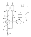
- Fig. 3 shows an alternative embodiment of a pneumatic system according to the invention, which makes it possible in a simple manner to realize an alternating admission to at least two recipients of a pneumatic system with a pressure medium flow.
- a first recipient 10 is connected via a throttle 44 and connecting means 88 with the suction side 18 of a feed pump 22.
- the pressure side 20 of the pump 22 is in turn connected via connecting means 90 and a throttle 58 to a second recipient 12.
- the pneumatic system according to the invention thus constitutes a closed circuit.
- the output valve 26 is, in the manner already described, possible air or other working fluid of outside into the system.
- the valve 26, which may be configured for example as a check valve, are opened.
- Fig. 3 is the reciprocal filling of the two recipients in a simple manner by reversing the direction of rotation of the feed pump 22, which may for example be designed in the form of a vane pump, possible.
- the motor 92 driving the delivery pump 22 can be regulated.
- the frequency of the alternating Druckstoffschbeetz Anlagenng be varied.
- the pump control unit 93 which may be part of a higher-level control unit, for example, information to various sensors 95, for example, sensors for weight, height or environmental parameters such as the vehicle interior temperature can be supplied.
- various sensors 95 for example, sensors for weight, height or environmental parameters such as the vehicle interior temperature
- stored in the control unit of the electric motor 92 curves a user and driving situation specific control of the pneumatic system can be realized. For example, the effect can be taken into account that, in the case of a strong irritation of the vehicle interior, the pressure in the recipient can rise due to a thermal expansion of the working fluid.
- various massage programs can be stored on the characteristic curves in the control unit and be retrieved, for example, by a corresponding control element by the vehicle user or the vehicle occupants.
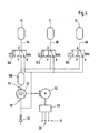
- Fig. 4 shows a further embodiment of a pneumatic circuit according to the invention, in which more than the at least two recipients are used.
- the illustrated three recipients are representative of any number of recipients that may include such a pneumatic system and are not intended to be limiting of the generality of the pneumatic circuit according to the invention.
- Fig. 4 In the embodiment of Fig. 4 three recipients 10, 11 and 12 are connected via respective connecting means 94, 96 and 98, each with an actuator 100, 102 and 104, respectively.
- the actuators for example, the pneumatic actuators according to the embodiment in Fig. 2 can connect in their, in Fig. 4 illustrated position the recipient 10, 11 and 12 with the suction side 18 of a feed pump 22. In this case, the actuators in Fig. 4 placed such that all three containers 10, 11, 12 are emptied simultaneously by the feed pump 22.
- An alternative circuit of the actuators is of course also possible in which, for example, a certain number of recipients is actively emptied, while a different number of existing recipients is acted upon simultaneously by the feed pump with the working fluid.
- the actuators of the pneumatic circuit according to the invention of those in Fig. 4 can be switched by respective switching programs synchronously or asynchronously to each other. In this way it is possible to have different massage programs with a constant Number of recipients in the pneumatic system to realize.
- the recipients 10, 11 and 12 are connected by the change of the actuators in its second possible position with the pressure side 20 of the feed pump, so that the working fluid in the second position of the actuators 10, 11 and 12 is pumped into the Rezpienten.
- the pressure side of the feed pump may also have, for example, a supply recipient 106, which is filled with the working fluid by the feed pump and can pass on the working fluid via a corresponding valve element to the recipient connected to the pressure side of the feed pump.
- the inventive method for alternately pressurizing a pneumatic system with a pressure medium flow or the corresponding pneumatic circuit for performing this method are not limited to the embodiments illustrated in the figures.
- the method and the associated device are not limited to the use of air as a working medium.
- air is preferred as the readily available and therefore inexpensive working fluid, other gaseous working fluids are also possible.
- the use of water or other liquid working fluids has the problem that a leak in the system can lead to moisture penetration of the vehicle seat, so that it can be foreseen from the use of liquid working fluids.
- the inventive method and the corresponding pneumatic circuit are not limited to the application in a massage system and in particular not limited to the use in the vehicle seats of a motor vehicle. Rather, such a pneumatic system can be used in a variety of technical applications.
Landscapes
- Engineering & Computer Science (AREA)
- Aviation & Aerospace Engineering (AREA)
- Transportation (AREA)
- Mechanical Engineering (AREA)
- Massaging Devices (AREA)
- Chair Legs, Seat Parts, And Backrests (AREA)
Claims (20)
- Procédé pour alimenter en alternance au moins deux récipients (10, 11, 12) d'un système pneumatique, notamment d'un système de massage pneumatique d'un siège de véhicule automobile avec un flux d'agent sous pression,
caractérisé en ce qu'
au moins l'un des réceptacles (10, 11, 12) servant de premier coussin à air (10, 11, 12) est rempli d'un fluide actif à l'état gazeux alors que le fluide actif est aspiré activement d'au moins un autre second coussin à air (10, 11, 12). - Procédé selon la revendication 1,
caractérisé en ce qu'
on utilise la pression dans au moins l'un des récipients (10, 11, 12) à vider pour remplir au moins un coussin d'air (10, 11, 12) à charger. - Procédé selon la revendication 1 ou 2,
caractérisé en ce qu'
on réalise le remplissage alterné d'au moins un coussin d'air (10, 11, 12) en inversant le sens de rotation d'une pompe (22) débitant le fluide actif. - Procédé selon la revendication 3,
caractérisé en ce que
la vitesse de rotation d'un moteur entraînant la pompe de refoulement (22) et notamment d'un moteur électrique (24, 92) est prédéfinie. - Procédé selon l'une des revendications précédentes,
caractérisé en ce que
la pression finale dans au moins l'un des récipients à remplir (10, 11, 12) et/ou la fréquence de la sollicitation alternée au moins des deux récipients (10, 11, 12) avec du fluide actif est ou sont prédéfinis. - Procédé selon la revendication 5,
caractérisé en ce que
la pression finale dans au moins l'un des récipients à remplir (10, 11, 12) et/ou la fréquence de l'alimentation alternée au moins des deux récipients (10, 11, 12) avec du fluide actif sont/est prédéfinie manuellement par des éléments de manoeuvre correspondants équipant le véhicule. - Procédé selon la revendication 5,
caractérisé en ce qu'
on prédéfinit la pression finale dans au moins l'un des récipients (10, 11, 12) à remplir et/ou la fréquence de l'alimentation alternée au moins des deux récipients (10, 11, 12) avec du fluide actif par un appareil de commande (93) en fonction des signaux d'au moins un capteur (95), notamment d'un capteur de détection d'occupation des sièges. - Procédé selon l'une des revendications 5, 6 ou 7,
caractérisé en ce qu'
on commande ou régule la pression finale dans au moins l'un des récipients à remplir (10, 11, 12) et/ou la fréquence de l'alimentation alternée au moins des deux récipients (10, 11, 12) avec du fluide actif par un moyen d'étranglement (34, 44, 58) du flux d'agent sous pression du côté pression (20) de la pompe de refoulement (22), notamment par une soupape d'étranglement (34, 44, 58). - Procédé selon l'une des revendications 5, 6 ou 7,
caractérisé en ce qu'
on commande ou régule la pression finale dans au moins un coussin d'air (10, 11, 12) à remplir et/ou la fréquence de l'alimentation alternée au moins des deux récipients (10, 11, 12) avec du fluide de travail par l'actionnement d'une dérivation (32) entre le côté aspiration (18) et le côté pression (côté refoulement) (20) de la pompe de refoulement (22). - Circuit pneumatique pour l'alimentation alternée de récipients (10, 11, 12) d'un système pneumatique, notamment d'un système de massage pneumatique d'un siège de véhicule avec un fluide d'agent sous pression comportant au moins deux récipients (10, 11, 12) pour recevoir en alternance le débit de fluide sous pression, au moins une pompe (22) refoulant du fluide sous pression ainsi que des moyens d'entraînement (24) de la pompe de refoulement (22) et des moyens de liaison (14, 16, 18, 20, 88, 90, 94, 96, 98) entre la pompe de refoulement (22) et les récipients (10, 121, 12) à alimenter en fluide actif,
caractérisé en ce qu'
au moins l'un des récipients, le premier récipient (10, 11, 12) est relié par les moyens de liaison (14, 16, 18, 20, 88, 90, 94, 96, 98) et la pompe de refoulement (22) avec au moins un second récipient (10, 11, 12). - Circuit pneumatique selon la revendication 10,
caractérisé en ce qu'
au moins les deux récipients (10, 11, 12) sont reliés par des moyens de liaison (14, 16, 18, 20, 88, 90, 94, 96, 98), avec au moins une pompe de refoulement (22) de façon qu'à partir d'au moins le premier récipient (10, 11, 12), le fluide actif pompé soit fourni au moins au second récipient (10, 11, 12). - Circuit pneumatique selon la revendication 10 ou 11,
caractérisé en ce que
le côté aspiration (18) au moins d'une pompe d'aspiration (22) est relié à au moins un premier des récipients (10, 11, 12) alors qu'en même temps le côté refoulement (côté de pression) (20) de la pompe de refoulement (22) est relié au moins avec un second récipient (10, 11, 12). - Circuit pneumatique selon l'une des revendications précédentes (10, 11, 12),
caractérisé en ce que
le côté aspiration (18) de la pompe de refoulement (22) est relié par un composant (36, 100, 102, 104) commandant le débit de fluide sous pression avec au moins un premier récipient (10, 11, 12) alors que le côté de refoulement (côté pression) (20) de la pompe (22) est en même temps relié à au moins un second récipient (10, 11, 12). - Circuit pneumatique selon la revendication 13,
caractérisé en ce que
le côté refoulement (côté pression) (20) de la pompe de refoulement (22) est en outre relié au même composant (36, 100, 102, 104) qui commande le débit de fluide sous pression. - Circuit pneumatique selon la revendication 13 ou 14,
caractérisé en ce que
le moyen de commande de pression (36, 100, 102, 104) est un organe d'actionnement (36, 100, 102, 104) à commande pneumatique. - Circuit pneumatique selon la revendication 15,
caractérisé en ce que
le moyen de commande de pression (36, 100, 102, 104) comporte au moins une soupape. - Circuit pneumatique selon l'une des revendications précédentes 10 à 16,
caractérisé en ce que
la pompe de refoulement (22) est une pompe à alvéoles et ailette, notamment pompe à alvéole et ailette comportant des moyens d'inversion de sens de rotation. - Circuit pneumatique selon l'une des revendications précédentes 10 à 17,
caractérisé en ce que
le circuit comporte au moins une soupape de sortie (26) qui, lorsqu'on atteint une certaine limite de pression du côté aspiration (18) de la pompe (22), ouvre une conduite de liaison (28, 14, 18, 88) pour assurer une alimentation supplémentaire de fluide actif dans le système. - Circuit pneumatique selon l'une des revendications précédentes 10 à 18,
caractérisé en ce que
le circuit comporte au moins un élément de capteur (95) qui recueille des informations concernant une occupation de siège et transmet ces informations à un appareil de commande (93) du circuit pneumatique. - Procédé d'alimentation d'au moins deux récipients (10, 11, 12) intégrés dans un siège de véhicule pour une alimentation alternée avec un débit d'agent sous pression,
caractérisé en ce que
l'alimentation des récipients (10, 11, 12) se fait selon un procédé suivant l'une des revendications 1 à 9.
Applications Claiming Priority (3)
| Application Number | Priority Date | Filing Date | Title |
|---|---|---|---|
| DE10238240A DE10238240A1 (de) | 2002-08-21 | 2002-08-21 | Verfahren zur Befüllung mindestens zweier Rezipienten sowie pneumatische Schaltung zur Durchführung des Verfahrens |
| DE10238240 | 2002-08-21 | ||
| PCT/DE2003/002508 WO2004020243A1 (fr) | 2002-08-21 | 2003-07-25 | Procede pour remplir au moins deux contenants et circuit pneumatique permettant de mettre en oeuvre ce procede |
Publications (2)
| Publication Number | Publication Date |
|---|---|
| EP1532016A1 EP1532016A1 (fr) | 2005-05-25 |
| EP1532016B1 true EP1532016B1 (fr) | 2008-05-28 |
Family
ID=31197172
Family Applications (1)
| Application Number | Title | Priority Date | Filing Date |
|---|---|---|---|
| EP03790652A Expired - Lifetime EP1532016B1 (fr) | 2002-08-21 | 2003-07-25 | Procede pour remplir au moins deux contenants et circuit pneumatique permettant de mettre en oeuvre ce procede |
Country Status (5)
| Country | Link |
|---|---|
| US (1) | US20050242644A1 (fr) |
| EP (1) | EP1532016B1 (fr) |
| JP (1) | JP2005536297A (fr) |
| DE (2) | DE10238240A1 (fr) |
| WO (1) | WO2004020243A1 (fr) |
Families Citing this family (11)
| Publication number | Priority date | Publication date | Assignee | Title |
|---|---|---|---|---|
| DE102004045573B4 (de) | 2004-09-17 | 2007-11-15 | Grammer Ag | Sitz mit einer Ergomechanik |
| US20110245743A1 (en) * | 2008-12-02 | 2011-10-06 | Medical Minds LLC | Compression device and control system for applying pressure to a limb of a living being |
| EP2361800B1 (fr) * | 2010-02-17 | 2013-04-24 | L & P Swiss Holding AG | Dispositif d'ajustement pour siège et procédé de fonctionnement d'un dispositif d'ajustement |
| EP2461046B1 (fr) * | 2010-12-03 | 2017-11-01 | Schukra Gerätebau GmbH | Ensemble de valve et dispositif d'ajustement de siège pneumatique |
| DE102010054492B4 (de) | 2010-12-14 | 2025-09-04 | Faurecia Autositze Gmbh | Massageeinrichtung für eine Rückenlehne eines Fahrzeugsitzes |
| US9211824B2 (en) * | 2012-04-30 | 2015-12-15 | Ford Global Technologies, Llc | Adjustable firmness vehicle seat |
| DE102012025306A1 (de) * | 2012-12-22 | 2014-06-26 | Daimler Ag | Sitzanlage für einen Kraftwagen |
| DE102014211486B4 (de) * | 2014-06-16 | 2021-08-19 | Conti Temic Microelectronic Gmbh | Pneumatische Verstellanordnung für einen Fahrzeugsitz und Fahrzeugsitz |
| DE102015113029B4 (de) | 2015-04-09 | 2022-05-25 | Alfmeier Präzision AG Baugruppen und Systemlösungen | Vorrichtung und Verfahren zur Einstellung einer Kontur eines Fahrzeugsitzes mit Konturverstellung |
| DE102016204845A1 (de) * | 2016-03-23 | 2017-09-28 | Brose Fahrzeugteile Gmbh & Co. Kommanditgesellschaft, Coburg | Verfahren zur Ansteuerung eines Motors einer in einem Sitz vorgesehenen Massageeinheit, Steuereinrichtung und Sitzanordnung |
| JP6856879B2 (ja) * | 2019-07-29 | 2021-04-14 | テイ・エス テック株式会社 | 乗物用シート |
Family Cites Families (15)
| Publication number | Priority date | Publication date | Assignee | Title |
|---|---|---|---|---|
| US2780222A (en) * | 1953-12-18 | 1957-02-05 | J J Monaghan Company Inc | Respirators |
| US4175297A (en) * | 1978-02-03 | 1979-11-27 | Richardson Robert H | Inflatable pillow support |
| JPS57126224A (en) * | 1981-01-27 | 1982-08-05 | Mitsubishi Electric Corp | Input circuit for protection relay unit |
| GB2144984A (en) * | 1983-08-13 | 1985-03-20 | Ian Leslie Cameron | Seat with variable support |
| US4989589A (en) * | 1983-11-07 | 1991-02-05 | Pekanmaeki Kalle | Device for massaging extermities, such as legs |
| US4655505A (en) * | 1984-12-13 | 1987-04-07 | Nhk Spring Co., Ltd. | Pneumatically controlled seat for vehicle |
| GB8526785D0 (en) * | 1985-10-30 | 1985-12-04 | Pirelli Ltd | Inflation pump |
| US4986260A (en) * | 1986-06-06 | 1991-01-22 | Superspine, Inc. | Apparatus and method for providing continuous passive motion to the spine |
| GB8804864D0 (en) * | 1988-03-01 | 1988-03-30 | Pirelli Ltd | System for inflating support bag in seat |
| JP2751431B2 (ja) * | 1989-07-14 | 1998-05-18 | 日産自動車株式会社 | シート |
| US5135282A (en) * | 1989-08-18 | 1992-08-04 | Man Nutzfahrzeuge Aktiengesellschaft | Motor vehicle seat back |
| US5029939A (en) * | 1989-10-05 | 1991-07-09 | General Motors Corporation | Alternating pressure pad car seat |
| IT1285059B1 (it) * | 1996-04-26 | 1998-06-03 | Magneti Marelli Spa | Depressore rotativo a palette. |
| DE19726409A1 (de) * | 1997-06-21 | 1998-12-24 | Bayerische Motoren Werke Ag | Sitz |
| US6361512B1 (en) * | 2000-02-23 | 2002-03-26 | Spencer L. Mackay | Massaging apparatus using inflatable bladders |
-
2002
- 2002-08-21 DE DE10238240A patent/DE10238240A1/de not_active Withdrawn
-
2003
- 2003-07-25 WO PCT/DE2003/002508 patent/WO2004020243A1/fr not_active Ceased
- 2003-07-25 US US10/525,308 patent/US20050242644A1/en not_active Abandoned
- 2003-07-25 EP EP03790652A patent/EP1532016B1/fr not_active Expired - Lifetime
- 2003-07-25 DE DE50309924T patent/DE50309924D1/de not_active Expired - Lifetime
- 2003-07-25 JP JP2004531422A patent/JP2005536297A/ja active Pending
Also Published As
| Publication number | Publication date |
|---|---|
| DE50309924D1 (de) | 2008-07-10 |
| JP2005536297A (ja) | 2005-12-02 |
| US20050242644A1 (en) | 2005-11-03 |
| DE10238240A1 (de) | 2004-03-04 |
| EP1532016A1 (fr) | 2005-05-25 |
| WO2004020243A1 (fr) | 2004-03-11 |
Similar Documents
| Publication | Publication Date | Title |
|---|---|---|
| DE60037894T2 (de) | Auf fahrzeugaufprall reagierender sitz und kopfstütze mit mehreren luftzellen und verfahren zur herstellung | |
| DE69920716T2 (de) | Verfahren in einem system zur regelung des komforts eines sitzes mit mehreren luftzellen, die interaktiv und individuell gesteuert sind. | |
| DE19750223C2 (de) | Verfahren zur fahrsituations- und fahrweisen bedingten Adaption der Seitenabstützung eines Sitzenden in einem Fahrzeugsitz und Fahrzeugsitz hierzu | |
| DE112013007448B4 (de) | Massagesystem für einen Fahrzeugsitz | |
| EP3310613B1 (fr) | Siège de véhicule | |
| EP1072465B1 (fr) | Siège de voiture à profil réglable | |
| EP1518748A2 (fr) | Dispositif et procédé pour commander et/ou regler des niveaux de pression | |
| DE69015679T2 (de) | Vorrichtung zum Aufblasen einer Rückenstütze eines Sitzes. | |
| EP1532016B1 (fr) | Procede pour remplir au moins deux contenants et circuit pneumatique permettant de mettre en oeuvre ce procede | |
| EP3142892B1 (fr) | Siège de véhicule doté d'une surface d'assise réglable et une methode de regler une surface d'assise | |
| DE102009016050A1 (de) | Auflage für einen Sitz | |
| DE3541537A1 (de) | Pneumatisch gesteuerter sitz fuer ein fahrzeug | |
| EP1374739A2 (fr) | Siège à profil réglable et module de support | |
| EP1839533A2 (fr) | Dispositif destiné à s'asseoir | |
| DE112017005086T5 (de) | Fahrzeugsitzvorrichtung und Luftdrucksteuerverfahren für Fahrzeugsitz | |
| EP0778173A2 (fr) | Siège avec des chambres à pression variable, qui comprennent une paroi de support élastique | |
| EP1404977B1 (fr) | Dispositif et procede de commande et de regulation pneumatique de courants de fluides hydrauliques | |
| EP1710120A2 (fr) | Siège de véhicule automobile ainsi que dispositif et procédé pour remplir et/ou vider des coussins gonflables | |
| DE102009012693A1 (de) | Sitz, insbesondere für ein Kraftfahrzeug | |
| DE3200139A1 (de) | Luftsacksystem, insbesondere fuer die polsterung von sitzrueckenlehnen in kraftfahrzeugen | |
| DE102024130536A1 (de) | Fluidsystem für Fahrzeugsitzanordnung | |
| DE102020215210A1 (de) | Fahrzeugsitz mit Seitenwangenverstellung | |
| DE102016224885B4 (de) | Fahrzeugsitz und Verfahren zur individuellen Anpassung seiner Sitz- und/oder Lehnflächenkontur an einen Sitzbenutzer | |
| DE102008009473A1 (de) | Vorrichtung und Verfahren zum Befüllen von aufblasbaren Fahrzeugsitz-Polsterelementen | |
| DE102021122458A1 (de) | Verfahren zum Betreiben der Massagefunktion eines Kraftfahrzeugsitzes in einem Kraftfahrzeugsitzsystem |
Legal Events
| Date | Code | Title | Description |
|---|---|---|---|
| PUAI | Public reference made under article 153(3) epc to a published international application that has entered the european phase |
Free format text: ORIGINAL CODE: 0009012 |
|
| 17P | Request for examination filed |
Effective date: 20050321 |
|
| AK | Designated contracting states |
Kind code of ref document: A1 Designated state(s): AT BE BG CH CY CZ DE DK EE ES FI FR GB GR HU IE IT LI LU MC NL PT RO SE SI SK TR |
|
| RIN1 | Information on inventor provided before grant (corrected) |
Inventor name: KONRAD, DANIEL Inventor name: BAUER, BERTRAM Inventor name: PAESSLER, WOLFGANG Inventor name: MERZ, HARALD |
|
| RBV | Designated contracting states (corrected) |
Designated state(s): CZ DE FR GB |
|
| GRAP | Despatch of communication of intention to grant a patent |
Free format text: ORIGINAL CODE: EPIDOSNIGR1 |
|
| GRAS | Grant fee paid |
Free format text: ORIGINAL CODE: EPIDOSNIGR3 |
|
| GRAA | (expected) grant |
Free format text: ORIGINAL CODE: 0009210 |
|
| AK | Designated contracting states |
Kind code of ref document: B1 Designated state(s): CZ DE FR GB |
|
| REG | Reference to a national code |
Ref country code: GB Ref legal event code: FG4D Free format text: NOT ENGLISH |
|
| REF | Corresponds to: |
Ref document number: 50309924 Country of ref document: DE Date of ref document: 20080710 Kind code of ref document: P |
|
| PG25 | Lapsed in a contracting state [announced via postgrant information from national office to epo] |
Ref country code: CZ Free format text: LAPSE BECAUSE OF FAILURE TO SUBMIT A TRANSLATION OF THE DESCRIPTION OR TO PAY THE FEE WITHIN THE PRESCRIBED TIME-LIMIT Effective date: 20080528 |
|
| PLBE | No opposition filed within time limit |
Free format text: ORIGINAL CODE: 0009261 |
|
| STAA | Information on the status of an ep patent application or granted ep patent |
Free format text: STATUS: NO OPPOSITION FILED WITHIN TIME LIMIT |
|
| GBPC | Gb: european patent ceased through non-payment of renewal fee |
Effective date: 20080828 |
|
| 26N | No opposition filed |
Effective date: 20090303 |
|
| PG25 | Lapsed in a contracting state [announced via postgrant information from national office to epo] |
Ref country code: GB Free format text: LAPSE BECAUSE OF NON-PAYMENT OF DUE FEES Effective date: 20080828 |
|
| REG | Reference to a national code |
Ref country code: DE Ref legal event code: R084 Ref document number: 50309924 Country of ref document: DE Effective date: 20120201 |
|
| PGFP | Annual fee paid to national office [announced via postgrant information from national office to epo] |
Ref country code: FR Payment date: 20130719 Year of fee payment: 11 |
|
| REG | Reference to a national code |
Ref country code: FR Ref legal event code: ST Effective date: 20150331 |
|
| PG25 | Lapsed in a contracting state [announced via postgrant information from national office to epo] |
Ref country code: FR Free format text: LAPSE BECAUSE OF NON-PAYMENT OF DUE FEES Effective date: 20140731 |
|
| REG | Reference to a national code |
Ref country code: DE Ref legal event code: R079 Ref document number: 50309924 Country of ref document: DE Free format text: PREVIOUS MAIN CLASS: B60N0002440000 Ipc: B60N0002900000 |
|
| REG | Reference to a national code |
Ref country code: DE Ref legal event code: R081 Ref document number: 50309924 Country of ref document: DE Owner name: CONTINENTAL AUTOMOTIVE GMBH, DE Free format text: FORMER OWNER: ROBERT BOSCH GMBH, 70469 STUTTGART, DE |
|
| PGFP | Annual fee paid to national office [announced via postgrant information from national office to epo] |
Ref country code: DE Payment date: 20190731 Year of fee payment: 17 |
|
| REG | Reference to a national code |
Ref country code: DE Ref legal event code: R119 Ref document number: 50309924 Country of ref document: DE |
|
| PG25 | Lapsed in a contracting state [announced via postgrant information from national office to epo] |
Ref country code: DE Free format text: LAPSE BECAUSE OF NON-PAYMENT OF DUE FEES Effective date: 20210202 |