EP1532040B1 - Carrosserie de voiture a structure portante composee de modules de grandes dimensions - Google Patents
Carrosserie de voiture a structure portante composee de modules de grandes dimensions Download PDFInfo
- Publication number
- EP1532040B1 EP1532040B1 EP03794855A EP03794855A EP1532040B1 EP 1532040 B1 EP1532040 B1 EP 1532040B1 EP 03794855 A EP03794855 A EP 03794855A EP 03794855 A EP03794855 A EP 03794855A EP 1532040 B1 EP1532040 B1 EP 1532040B1
- Authority
- EP
- European Patent Office
- Prior art keywords
- module
- body according
- basic module
- sections
- basic
- Prior art date
- Legal status (The legal status is an assumption and is not a legal conclusion. Google has not performed a legal analysis and makes no representation as to the accuracy of the status listed.)
- Expired - Lifetime
Links
- 239000002131 composite material Substances 0.000 description 5
- 238000010276 construction Methods 0.000 description 5
- 239000000853 adhesive Substances 0.000 description 2
- 230000001070 adhesive effect Effects 0.000 description 2
- 238000005516 engineering process Methods 0.000 description 2
- 238000004519 manufacturing process Methods 0.000 description 2
- 239000002184 metal Substances 0.000 description 2
- 238000004378 air conditioning Methods 0.000 description 1
- 230000013011 mating Effects 0.000 description 1
- 238000005058 metal casting Methods 0.000 description 1
- 230000001502 supplementing effect Effects 0.000 description 1
Images


Classifications
-
- B—PERFORMING OPERATIONS; TRANSPORTING
- B62—LAND VEHICLES FOR TRAVELLING OTHERWISE THAN ON RAILS
- B62D—MOTOR VEHICLES; TRAILERS
- B62D25/00—Superstructure or monocoque structure sub-units; Parts or details thereof not otherwise provided for
- B62D25/04—Door pillars ; windshield pillars
-
- B—PERFORMING OPERATIONS; TRANSPORTING
- B62—LAND VEHICLES FOR TRAVELLING OTHERWISE THAN ON RAILS
- B62D—MOTOR VEHICLES; TRAILERS
- B62D21/00—Understructures, i.e. chassis frame on which a vehicle body may be mounted
- B62D21/12—Understructures, i.e. chassis frame on which a vehicle body may be mounted assembled from readily detachable parts
-
- B—PERFORMING OPERATIONS; TRANSPORTING
- B62—LAND VEHICLES FOR TRAVELLING OTHERWISE THAN ON RAILS
- B62D—MOTOR VEHICLES; TRAILERS
- B62D25/00—Superstructure or monocoque structure sub-units; Parts or details thereof not otherwise provided for
- B62D25/02—Side panels
-
- B—PERFORMING OPERATIONS; TRANSPORTING
- B62—LAND VEHICLES FOR TRAVELLING OTHERWISE THAN ON RAILS
- B62D—MOTOR VEHICLES; TRAILERS
- B62D25/00—Superstructure or monocoque structure sub-units; Parts or details thereof not otherwise provided for
- B62D25/06—Fixed roofs
-
- B—PERFORMING OPERATIONS; TRANSPORTING
- B62—LAND VEHICLES FOR TRAVELLING OTHERWISE THAN ON RAILS
- B62D—MOTOR VEHICLES; TRAILERS
- B62D25/00—Superstructure or monocoque structure sub-units; Parts or details thereof not otherwise provided for
- B62D25/08—Front or rear portions
- B62D25/082—Engine compartments
-
- B—PERFORMING OPERATIONS; TRANSPORTING
- B62—LAND VEHICLES FOR TRAVELLING OTHERWISE THAN ON RAILS
- B62D—MOTOR VEHICLES; TRAILERS
- B62D25/00—Superstructure or monocoque structure sub-units; Parts or details thereof not otherwise provided for
- B62D25/20—Floors or bottom sub-units
- B62D25/2009—Floors or bottom sub-units in connection with other superstructure subunits
- B62D25/2018—Floors or bottom sub-units in connection with other superstructure subunits the subunits being front structures
-
- B—PERFORMING OPERATIONS; TRANSPORTING
- B62—LAND VEHICLES FOR TRAVELLING OTHERWISE THAN ON RAILS
- B62D—MOTOR VEHICLES; TRAILERS
- B62D25/00—Superstructure or monocoque structure sub-units; Parts or details thereof not otherwise provided for
- B62D25/20—Floors or bottom sub-units
- B62D25/2009—Floors or bottom sub-units in connection with other superstructure subunits
- B62D25/2036—Floors or bottom sub-units in connection with other superstructure subunits the subunits being side panels, sills or pillars
-
- B—PERFORMING OPERATIONS; TRANSPORTING
- B62—LAND VEHICLES FOR TRAVELLING OTHERWISE THAN ON RAILS
- B62D—MOTOR VEHICLES; TRAILERS
- B62D65/00—Designing, manufacturing, e.g. assembling, facilitating disassembly, or structurally modifying motor vehicles or trailers, not otherwise provided for
- B62D65/02—Joining sub-units or components to, or positioning sub-units or components with respect to, body shell or other sub-units or components
- B62D65/04—Joining preassembled modular units composed of sub-units performing diverse functions, e.g. engine and bonnet
Definitions
- the invention relates to a body for a motor vehicle specified in the preamble of claim 1. Art.
- a body is already out of the WO 96 13421 A as known, whose support structure is composed of two large-sized sub-modules.
- a base module forming the rear region of the support structure comprises lateral side members as well as a body floor, via which the basic module is connected to a front submodule.
- the base module is connected in the region of lateral upper roof pillars with a windshield frame, which is associated with the front module.
- the front module is thus crash-stable supported on the base module to form a front crumple zone of the motor vehicle.
- a front end region of the body floor belongs to the front end module and extends rearwardly between lateral longitudinal beam sections of the basic module over a considerable length range.
- a disadvantage of the present body is the fact that the front module is only sufficiently stable supported by the attachment of this windshield frame associated with the roof construction on the base module.
- the support structure is made as a chassis of extruded lightweight panels.
- the chassis comprises a base module with lateral side rails and with a body floor formed from lightweight panels, opposite is arranged to spring back the side rails.
- This base module is to be connected to a front module comprising a front end wall and a sloping pedal base.
- this front module includes two lightweight panels, which form the front end of the body floor with a composite chassis. The two lightweight panels extend over a considerable length range of the basic module to the rear.
- This basic module has a body floor extending between lateral side members, which is arranged so as to be recessed relative to the lateral side members or to side walls of the basic module.
- the base module is to be connected to a front module, which comprises an end region of the body floor extending rearwardly from a front end wall.
- the front wall itself is to be connected to the side walls of the basic module.
- From the FR 2 618 746 A is to take a body as known, at the base module to attach a front module.
- a front module For this purpose, two longitudinal members of the front-end module running close to the center of the vehicle in the longitudinal direction of the vehicle are inserted into corresponding receptacles on the underbody of the basic module.
- a body known whose support structure is composed of substantially four large-sized sub-modules whose support structure is composed of substantially four large-sized sub-modules.
- One of the sub-modules is designed as a laterally to front wall pillars heranvrades basic module with side rails and a body floor.
- the basic module is connected to a partial module designed as a front-end module which belongs to the front crumple zone of the motor vehicle and is supported on the basic module in a crash-stable manner is.
- a roof module or by provided at the front end of the basic module roof sections creates a stable connection of Vorbaumoduls on the base module.
- the invention has for its object to provide a bodywork for a motor vehicle, in which the frontal module is already set without roof construction in a more stable manner on the base module.
- upwardly projecting pillar portions are arranged at the front ends of the lateral side rail portions of the basic module, which are connectable to projecting at the lateral side rail portions of the front module upwardly column portions of the front boom module.
- the longitudinal beam sections of the front module and the basic module - via the associated column sections - are connected to each other in the vertical direction and there is a total of a stable angular attachment of the longitudinal beam and column sections of Vorbaumoduls and the basic module.
- the support structure for vehicles with different structure is used because the front module is already sufficiently stable without roof construction attached to the base module. This also results in a particularly good suitability of the support structure for open vehicles.
- the upwardly projecting column sections preferably extend approximately at right angles to the extension direction of the longitudinal members.
- the mutually associated, upwardly projecting column sections of the front module and the basic module can be connected to each other, for example, via each mating joining surfaces to front door pillars, so that on the one hand a particularly good connection of Vorbaumoduls results on the base module and on the other hand stiff and stable door pillars - preferably up At the height of the side wall edge of the support structure - are created. Between the door pillars preferably extends a front end wall which stiffen the door pillars in the vehicle transverse direction.
- connection between the front module and the base module is particularly stable when the mutually associated lateral side rail sections of the front module and the basic module are connected to each other via joining surfaces which extend over the at least approximately entire overlap length of the mutually associated side rail sections or the two modules.
- the lateral side rail portions of the front end module and the base module each have a box section closed in cross-section. After joining the mutually associated longitudinal beam sections thus lateral side members are created with a double box profile in cross-section, which are particularly stiff.
- the upwardly projecting column sections of the front module and the basic module preferably each comprise a box section closed in cross-section, so that particularly rigid door pillars are created with double cross-section box profile after joining the mutually laterally associated column sections.
- the support structure After assembly of the large-sized sub-modules, the support structure is to be clad with constraintsbeplankungs negligence, which hide the joints of the sub-modules with the specificallybeplankungs negligence. This ensures that the sub-modules on the one hand with sufficient tolerances manufacturing technology can be easily and thus inexpensively joined and on the other hand Covering the joints with a high quality impression is created.
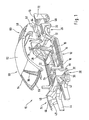
- FIG. 1 shows in a perspective exploded view a support structure 10 of a motor vehicle body, which is composed of a plurality of large-format sub-modules, which will be described in more detail below.
- the submodules of the support structure 10 are each made in the embodiment shown here from a plurality of assembled sheet metal parts; However, the sub-modules can also be prefabricated in other constructions, for example as so-called. Spaceframe, as plastic parts, metal castings, as components in so-called. Sandwich construction or the like.
- combinations of different designs for the assembled sub-modules depending on the application and load are conceivable.
- the individual modules are assembled in particular via adhesive bonds, welded joints or the like. Likewise, other common connections such as screw or the like. Imagine.
- a base module 12 of the support structure 10, which can be seen in conjunction with FIG. 1, comprises essentially a body floor 14, which is delimited laterally by longitudinal members 15.
- the basic module 12 extends with longitudinal beam sections 16 to column sections 18 of front wall columns 20, which project from the respective associated front ends of the side longitudinal beam sections 16 upwards.
- the body floor 14 of the base module 12 terminates at a considerable distance behind the front end of the base module 12 and behind the column sections 18 of the front wall pillars 20.
- the body floor 14 is here provided with a center tunnel 22 and extending outwardly therefrom cross members 24, which are firmly connected to the longitudinal members 15.
- the basic module 12 ends behind rear wheel arches 26, on the inside of which extensions 28 of the lateral side members 15 extend.
- the body floor 14 terminates at the rear on a cross member 32 which extends between the extensions 28 of the lateral side members 15 at the level of the rear wheel arches 26 in the vehicle transverse direction.
- the basic module 12 is equipped as far as possible prior to assembly with the other sub-modules.
- the interior trim, possibly the seat, the electrical and electronic equipment, or the underfloor system for example, with parts of the exhaust system already attached to the base module and possibly with adapters, connectors or the like. Provided that allow connection with other components.
- Vorbaumodul 34 is connected, which belongs to the front crumple zone of the motor vehicle and crash-stable on the base module 12 is supported.
- the front module 34 comprises a front end region 36 of the body floor 14, which extends between lateral side member sections 38 of the front module 34.
- the front end region 36 of the body floor 14 and the lateral side rail sections 38 end toward the rear at least approximately at a height.
- the end wall 40 is bounded by column sections 42 of the front wall columns 20, which project upwards from the lateral side member sections 38 of the front module 34.
- front longitudinal members 44 and front side wall portions 46 can be seen, between which parts 48 of the wheel arch lining of the front wheel arches are arranged.
- the front module 34 is adjoined by a front module 35, which is partially shown in FIG.
- This front module 35 includes, for example the front bumper, the front end of the motor vehicle, the headlights, parts of the radiator and parts of the wheel arch trim.
- the front module 34 is also equipped as far as possible before assembly with the other submodules. In particular, not shown components and units such as the dashboard, the air conditioning, the pedal system, etc. may already be attached to the front module.
- a roof module 50 which can be seen in conjunction with FIG. 9 can be placed on the basic module 12 and the front module 34, which lateral lateral A columns 54, lateral roof columns 56, and C columns 58 in the region of the roof 52.
- the lower ends of the A-pillars 54 and the C-pillars 58 are connected to one another via a respective cross-member element 60.
- the A-pillars 54 are based on composite support structure 10 both on the base module 12 and on the front module 34 from. In other words, the A-pillars 54 are supported with their lower ends on both the upstanding column sections 18 and 42 of the base module 12 and the front module 34, which form the respective front wall pillar 20.
- Rear joining surfaces 62 of the lower ends of the C-pillars 58 are attached with joining surfaces 64 at the respectively associated upper end of the wall portions 30, for example by means of an adhesive bond.
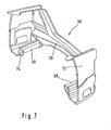
- the base module 12 is adjoined by a rear module 66, which can be seen together with FIG. 7, which belongs to the rear crumple zone of the motor vehicle together with the rear end region of the base module 12 and essentially lateral rear side rail sections 68, one of the side rail sections 68 connecting rear cross member 70 and rear side wall portions 72 includes.
- a rear module 66 which can be seen together with FIG. 7, which belongs to the rear crumple zone of the motor vehicle together with the rear end region of the base module 12 and essentially lateral rear side rail sections 68, one of the side rail sections 68 connecting rear cross member 70 and rear side wall portions 72 includes.
- the cross member 32 and the longitudinal beam extensions 28 of the base module 12 and by the side rail portions 68 and the rear cross member 70 of the rear module 66 is formed in composite support structure, a support frame, within which a spare wheel well, not shown attachable. It can be seen that the rear module 66 is connected to the base module 12 and the roof module 50 along a vertically extending vehicle transverse plane.
- a respective associated B-pillar 78 is fastened between the lateral roof pillar 56 of the roof module 50 and the lateral side member 15 of the basic module 12.
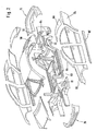
- FIG. 2 shows, in a further perspective exploded view, the support structure 10 composed of the submodules 12, 34, 50 and 66, which is clad with exterior paneling parts made of plastic, sheet metal or the like.
- front fender panels 80 are formed so that the joint 81 is covered between the upwardly projecting column sections 18 and 42 of the base module 12 and the Vorbaumoduls 34 and is not visible from the outside.
- attachment points of the A-pillars 54 of the roof module 50 to the base module 12 and the front module 34 are also covered by the front fender panels 80 and not visible.
- Lateral sill panels 82 are formed so that the joint 83 between the respective side rail portions 16 of the base module 12 and the longitudinal beam portions 38 of the front module 34 is not concealed from the outside visible.
- Rear fender panels 84 are also formed so that the joint 62,64 between the C-pillar 58 and the rear wall portion 30 is also not visible from the outside laminated. It can be seen that thus all joints of the large-sized sub-modules 12,34,50 and 66 covered with the trim parts 80,82,84 and are not visible from the outside. This ensures that the sub-modules with sufficient tolerances manufacturing technology can be easily and thus inexpensively joined and on the other hand, the cover of the joints a high quality impression is conveyed.
- the A-pillars 54, the side roof pillars 56 and the C-pillars 58 are lined with pillar trim parts 86, 88.
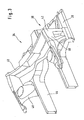
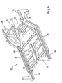
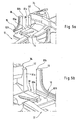
- FIGS. 5a and 5b show, in partial perspective views, the assembly of the basic module 12 and the front module 34
- FIG. 6 shows in perspective view the basic module 12 and the front module 34 after assembly.
- the front end region 36 of the body floor 14 belonging to the front module 34 extends rearwardly between the lateral side rail sections 16 over a considerable length of the base module 12.
- the mutually associated lateral side member sections 16, 38 of the front module 34 and of the base module 12 have matching joining surfaces 83 a, b at the respective joint 83 (FIG. 2), which extend over the at least approximately entire overlap length of the mutually associated side member sections 16,38 extend.
- the length of the joining surfaces 83a, b corresponds approximately to the length of the adjacent front end region 36 of the body floor 14.
- the lateral side rail sections 16, 38 of the front module 34 and the base module 12 each have a box profile closed in cross-section, so that after the assembly of each other associated side rail sections 16,38 lateral side members in the Cross-section double, about 8-shaped box profile arise.
- the box profile of the lateral longitudinal beam sections 16,38 of the front module 34 and the base module 12 each has a variable over its length, here stepped cross-section.
- the longitudinal beam sections 16, 38 are each designed as a partial shell, which are then connected to form a carrier.
- the upwardly projecting column sections 18, 42 of the basic module 12 and the front module 34 each comprise mutually adapted joining surfaces 81 a, b at the respective joint 81 (FIG. 2), via which the column sections 18, 42 are connected to the front wall pillar 20.
- the upwardly projecting column sections 18, 42 each comprise a box profile closed in cross-section, so that after assembly of the respectively associated column sections 18, 42, particularly rigid door pillars 20 having a cross-sectionally double, approximately 8-shaped box profile are created.
- the joining surfaces 81a, b of the column sections 18, 42 and the joining surfaces 83a, b of the side member sections 16, 38 run here at least approximately at right angles to one another.
- the position of the basic module 12 and the front end module 34 is thus determined in the vehicle longitudinal direction and in the vehicle vertical direction by the joining surfaces 83a, b and 81a, b.
- the position of the base module 12 and the front module 34 is not determined by the joining surfaces 83a, b and 81a, b, but for example by contact surfaces of the base module 12 and the Vorbaumoduls 34 in the region of the center tunnel 22.
- the center tunnel 22 is formed both in the front end portion 36 as well as in the body floor 14 and provided with joining surfaces.
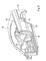
- FIG. 9 is a fragmentary perspective view of the assembled support structure 10, which includes a left and a right side wall module 100 extending from behind the front side doors to the rear door pillars.
- the side wall module 100 is fastened to the base module 12 above the associated longitudinal member 15 and opposite the rear side wall 30.
- the side wall module 100 is supported in the vehicle transverse direction with a support assembly 102 relative to a cross member 104.
- the base module 12 and the side wall module 100 terminate at the level of a common joining surface 106, on which a coupé roof module 50 'different in this respect is fastened with a side wall region 108.
Landscapes
- Engineering & Computer Science (AREA)
- Chemical & Material Sciences (AREA)
- Combustion & Propulsion (AREA)
- Transportation (AREA)
- Mechanical Engineering (AREA)
- Manufacturing & Machinery (AREA)
- Body Structure For Vehicles (AREA)
Claims (16)
- Carrosserie pour un véhicule automobile, dont la structure portante (10) est constituée de modules partiels de grandes dimensions (12, 34, 50, 66), un module de base (12) comprenant des supports longitudinaux latéraux (15) ainsi qu'un sol de la carrosserie (14), et s'étendant latéralement jusqu'aux colonnes de la paroi avant (20), le module de base (12), lorsque la structure portante (10) est assemblée, étant connecté à un module de structure avant (34) qui appartient à la zone déformable avant du véhicule automobile et qui est supporté sur le module de base (12) de manière stable en cas de collision, une région d'extrémité avant (36) du sol de la carrosserie (14) appartenant au module de structure avant (34) et s'étendant vers l'arrière entre des portions latérales des supports longitudinaux (16) sur une région longitudinale considérable du module de base (12), et le module de structure avant (34) comprenant des portions de supports longitudinaux (38) délimitant latéralement la région d'extrémité avant (36) du sol de la carrosserie (14), lesquelles peuvent être connectées aux portions latérales des supports longitudinaux (16) du module de base (12),
caractérisée en ce que
des portions de colonne (18) saillant vers le haut sont prévues au niveau des extrémités avant des portions latérales des supports longitudinaux (16) du module de base (12) et peuvent être connectées à des portions de colonne (42) du module de structure avant (34), saillant vers le haut sur les portions latérales des supports longitudinaux (38) du module de structure avant (34). - Carrosserie selon la revendication 1,
caractérisée en ce que
les portions latérales des supports longitudinaux (16, 38) associées les unes aux autres, du module de structure avant (34) et du module de base (12), présentent des surfaces de joint (83a,b) adaptées les unes aux autres, qui s'étendent sur au moins approximativement toute la longueur de recouvrement des portions des supports longitudinaux (16, 38) associées les unes aux autres. - Carrosserie selon la revendication 2,
caractérisée en ce que
la longueur des surfaces de joint (83a,b) correspond approximativement à la longueur de la région d'extrémité avant adjacente (36) du sol de la carrosserie (14). - Carrosserie selon la revendication 1,
caractérisée en ce que
les portions latérales des supports longitudinaux (38) du module de structure avant (34) et de la région d'extrémité avant (36) du sol de la carrosserie (14) s'étendent vers l'arrière approximativement sur la même longueur. - Carrosserie selon la revendication 1,
caractérisée en ce que
les portions latérales des supports longitudinaux (16, 38) du module de structure avant (34) et du module de base (12) présentent à chaque fois un profil de caisse de section transversale fermée. - Carrosserie selon la revendication 5,
caractérisée en ce que
le profil de caisse des portions latérales des supports longitudinaux (16, 38) du module de structure avant (34) et du module de base (12) présente à chaque fois une section transversale variable sur sa longueur. - Carrosserie selon la revendication 1,
caractérisée en ce
qu'une paroi frontale (40) avant est fixée entre les portions de colonne (42) du module de structure avant (34) saillant vers le haut. - Carrosserie selon la revendication 1,
caractérisée en ce que
les portions de colonne (18, 42) saillant vers le haut, du module de structure avant (34) et du module de base (12), peuvent être connectées les unes aux autres pour former les colonnes de paroi avant (20), par le biais de surfaces de joint respectives (81a,b) adaptées les unes aux autres. - Carrosserie selon la revendication 1,
caractérisée en ce que
les portions de colonne (18, 42) saillant vers le haut, du module de structure avant (34) et du module de base (12), présentent à chaque fois un profil de caisse de section transversale fermée et s'étendent jusqu'à environ la hauteur de l'arête de la paroi de bord de la structure portante (10). - Carrosserie selon la revendication 1,
caractérisée en ce que
la région d'extrémité (36) du sol de la carrosserie (14) appartenant au module de structure avant (34) est connectée à la région du sol de la carrosserie (14) appartenant au module de base (12) avec un chevauchement. - Carrosserie selon la revendication 1,
caractérisée en ce que
le module de base (12) se termine derrière les passages de roue arrières (26) et peut être connecté à un module arrière (66) qui, lorsque la structure portante (10) est assemblée, appartient conjointement avec la région d'extrémité arrière du module de base (12) à la zone déformable arrière du véhicule automobile. - Carrosserie selon la revendication 1,
caractérisée en ce que
l'on peut poser sur le module de base (12) et le module de structure avant (34) un module de toit (50) dont les colonnes de toit avant (54) s'appuient à la fois sur le module de base (12) et sur le module de structure avant (34). - Carrosserie selon la revendication 12,
caractérisée en ce que
le module de toit (50) comprend un support transversal (60) s'étendant en dessous du pare-brise, qui relie entre elles les colonnes de la paroi avant (20). - Carrosserie selon la revendication 12,
caractérisée en ce
qu'une colonne B (78) peut être fixée entre le module de toit (50) et le module de base (12). - Carrosserie selon la revendication 1,
caractérisée en ce
qu'un module de paroi latérale (100) respectif peut être fixé sur le module de base (12) au-dessus du support longitudinal (15) et s'étend depuis l'arrière des portes latérales avant jusqu'aux colonnes de porte arrière (58). - Carrosserie selon la revendication 1,
caractérisée en ce que
la structure portante (10) peut être revêtue de pièces de revêtement extérieur (80, 82, 84), les zones de joint (62, 64, 81, 83) des modules partiels (12, 34, 50, 66) étant couvertes par les pièces de revêtement extérieur (80, 82, 84).
Applications Claiming Priority (3)
| Application Number | Priority Date | Filing Date | Title |
|---|---|---|---|
| DE10239992 | 2002-08-27 | ||
| DE10239992A DE10239992A1 (de) | 2002-08-27 | 2002-08-27 | Kraftwagen-Karosserie mit einer Tragstruktur aus großformatigen Teilmodulen |
| PCT/EP2003/008818 WO2004024543A1 (fr) | 2002-08-27 | 2003-08-08 | Carrosserie de voiture a structure portante composee de modules de grandes dimensions |
Publications (2)
| Publication Number | Publication Date |
|---|---|
| EP1532040A1 EP1532040A1 (fr) | 2005-05-25 |
| EP1532040B1 true EP1532040B1 (fr) | 2007-10-03 |
Family
ID=31724202
Family Applications (1)
| Application Number | Title | Priority Date | Filing Date |
|---|---|---|---|
| EP03794855A Expired - Lifetime EP1532040B1 (fr) | 2002-08-27 | 2003-08-08 | Carrosserie de voiture a structure portante composee de modules de grandes dimensions |
Country Status (7)
| Country | Link |
|---|---|
| US (1) | US20060108834A1 (fr) |
| EP (1) | EP1532040B1 (fr) |
| JP (1) | JP2005537182A (fr) |
| KR (1) | KR20050051651A (fr) |
| CN (1) | CN1684866A (fr) |
| DE (2) | DE10239992A1 (fr) |
| WO (1) | WO2004024543A1 (fr) |
Families Citing this family (31)
| Publication number | Priority date | Publication date | Assignee | Title |
|---|---|---|---|---|
| DE10239990B4 (de) * | 2002-08-27 | 2007-10-25 | Daimlerchrysler Ag | Kraftwagen-Karosserie mit einer Tragstruktur aus großformatigen Teilmodulen |
| DE102004035530B4 (de) * | 2004-07-22 | 2020-08-13 | Bayerische Motoren Werke Aktiengesellschaft | Fahrzeugkarosserie mit zumindest einem Vorderwagen und einer Fahrgastzelle |
| US7810876B2 (en) * | 2007-01-11 | 2010-10-12 | Ford Motor Company | Vehicle having a rear end body structure |
| US8123284B2 (en) * | 2007-01-11 | 2012-02-28 | Ford Motor Company | Vehicle body component and mating feature |
| US8177277B2 (en) * | 2007-01-11 | 2012-05-15 | Ford Motor Company | Vehicle having a body panel |
| US7618087B2 (en) * | 2007-01-11 | 2009-11-17 | Ford Motor Company | Vehicle having a front end body structure |
| US7591502B2 (en) * | 2007-01-11 | 2009-09-22 | Ford Motor Company | Tunable inner fender structure |
| US7850226B2 (en) | 2007-01-11 | 2010-12-14 | Ford Motor Company | Vehicle having a passenger compartment body structure |
| US8317964B2 (en) * | 2007-01-11 | 2012-11-27 | Ford Motor Company | Method of manufacturing a vehicle |
| US8038205B2 (en) * | 2007-01-11 | 2011-10-18 | Ford Motor Company | Vehicle having a passenger compartment body structure |
| US7798560B2 (en) * | 2007-01-11 | 2010-09-21 | Ford Motor Company | Vehicle body structure |
| US7677649B2 (en) * | 2007-01-11 | 2010-03-16 | Ford Motor Company | Vehicle having an interlocking floor assembly |
| US7703841B2 (en) * | 2007-01-11 | 2010-04-27 | Ford Motor Company | Vehicle body assembly |
| US7717465B2 (en) * | 2007-01-11 | 2010-05-18 | Ford Motor Company | Vehicle having an engine support structure |
| US7849601B2 (en) * | 2007-01-11 | 2010-12-14 | Ford Motor Company | Method of manufacturing a vehicle |
| DE102008036870A1 (de) * | 2008-08-07 | 2010-02-11 | Dr. Ing. H.C. F. Porsche Aktiengesellschaft | Fahrzeugaufbau |
| DE102010051271A1 (de) * | 2010-11-12 | 2012-05-16 | Gm Global Technology Operations Llc (N.D.Ges.D. Staates Delaware) | Kraftfahrzeugkarosserie mit Verstärkungsstruktur |
| DE102011014338A1 (de) * | 2011-03-18 | 2012-09-20 | GM Global Technology Operations LLC (n. d. Gesetzen des Staates Delaware) | Bodenmodul für ein Kraftfahrzeug mit angeformten Formschlussmitteln |
| JP5928870B2 (ja) * | 2011-11-29 | 2016-06-01 | スズキ株式会社 | サイドフレームの周辺構造 |
| DE102013003702B4 (de) | 2013-03-04 | 2018-10-18 | Audi Ag | Karosserie für ein Fahrzeug |
| US9371093B1 (en) * | 2014-12-03 | 2016-06-21 | Toyota Motor Engineering & Manufacturing North America, Inc. | Vehicles having upper side member reinforcement portions |
| DE102015210330A1 (de) | 2015-06-03 | 2016-12-08 | Bayerische Motoren Werke Aktiengesellschaft | Gruppe von Kraftfahrzeugen |
| ITUA20164332A1 (it) * | 2016-06-13 | 2017-12-13 | Claudio Buccini | Dispositivo per il montaggio di sedili per autoveicoli |
| DE102016218794A1 (de) | 2016-09-29 | 2018-03-29 | Robert Bosch Gmbh | Stationärer Erdgasmotor mit wenigstens einem Stickoxidsensor |
| EP3434565B1 (fr) * | 2017-07-26 | 2021-01-20 | Toyota Jidosha Kabushiki Kaisha | Structure de section latérale de véhicule |
| DE102018205826A1 (de) * | 2018-04-17 | 2019-10-17 | Röchling Automotive SE & Co. KG | Kfz-Karosserie mit Rohkarosse und Fahrzeugboden sowie einem Sicherungsstrukturbauteil |
| CN111845950B (zh) * | 2019-04-24 | 2021-10-15 | 上海汽车集团股份有限公司 | 一种mpv车型或van车型的上车体 |
| DE102019122195A1 (de) | 2019-08-19 | 2021-02-25 | Bayerische Motoren Werke Aktiengesellschaft | Gruppe von Kraftfahrzeugen |
| JP7276012B2 (ja) * | 2019-08-30 | 2023-05-18 | スズキ株式会社 | 車体下部構造 |
| JP7359043B2 (ja) * | 2020-03-06 | 2023-10-11 | マツダ株式会社 | 車両の側部車体構造 |
| DE102020004925A1 (de) | 2020-08-13 | 2021-09-02 | Daimler Ag | Verbindungsanordnung einer Vorbaustruktur mit einer jeweiligen Seitenwandstruktur einer Karosserie eines Kraftwagens |
Family Cites Families (12)
| Publication number | Priority date | Publication date | Assignee | Title |
|---|---|---|---|---|
| FR2618746B1 (fr) * | 1987-07-28 | 1989-12-22 | Peugeot | Structure amovible de vehicule automobile et procede de montage d'un vehicule comportant une telle structure |
| JPH064988B2 (ja) * | 1988-10-11 | 1994-01-19 | マツダ株式会社 | 車両のドアロック装置 |
| KR960007333B1 (ko) * | 1991-05-10 | 1996-05-31 | 마쓰다 가부시끼가이샤 | 자동차의 제조방법 |
| DE4228120A1 (de) * | 1992-08-25 | 1994-03-03 | Opel Adam Ag | Kraftfahrzeug in Modulbauweise |
| DE4313562A1 (de) * | 1993-04-26 | 1994-10-27 | Opel Adam Ag | Karosserie für Kraftfahrzeuge |
| DE4330559C2 (de) * | 1993-09-09 | 1998-04-09 | Opel Adam Ag | Kraftfahrzeug in Modulbauweise |
| DE4438214A1 (de) * | 1994-10-26 | 1996-05-02 | Norbert Basler | Verfahren zur Herstellung eines Kraftfahrzeugs |
| DE19833395C2 (de) * | 1998-07-24 | 2002-06-27 | Daimler Chrysler Ag | Selbsttragende Kraftfahrzeugkarosserie |
| DE19860030A1 (de) * | 1998-12-23 | 2000-06-29 | Bayerische Motoren Werke Ag | Fahrzeugstruktur mit Schwellern und vorderen Längsträgern |
| US6460918B1 (en) * | 1999-10-19 | 2002-10-08 | Nissan Motor Co., Ltd. | Vehicle body structure |
| CA2303953A1 (fr) * | 2000-01-06 | 2001-07-06 | The Crown Divisions | Systeme et methode de conversion de vehicule |
| JP2001301653A (ja) * | 2000-04-25 | 2001-10-31 | Nissan Motor Co Ltd | 自動車の車体組立方法および車体構造 |
-
2002
- 2002-08-27 DE DE10239992A patent/DE10239992A1/de not_active Ceased
-
2003
- 2003-08-08 DE DE50308321T patent/DE50308321D1/de not_active Expired - Lifetime
- 2003-08-08 EP EP03794855A patent/EP1532040B1/fr not_active Expired - Lifetime
- 2003-08-08 CN CNA038230615A patent/CN1684866A/zh active Pending
- 2003-08-08 WO PCT/EP2003/008818 patent/WO2004024543A1/fr not_active Ceased
- 2003-08-08 JP JP2004535068A patent/JP2005537182A/ja not_active Abandoned
- 2003-08-08 KR KR1020057003414A patent/KR20050051651A/ko not_active Ceased
- 2003-08-08 US US10/525,948 patent/US20060108834A1/en not_active Abandoned
Also Published As
| Publication number | Publication date |
|---|---|
| US20060108834A1 (en) | 2006-05-25 |
| DE50308321D1 (de) | 2007-11-15 |
| EP1532040A1 (fr) | 2005-05-25 |
| WO2004024543A1 (fr) | 2004-03-25 |
| KR20050051651A (ko) | 2005-06-01 |
| DE10239992A1 (de) | 2004-03-18 |
| CN1684866A (zh) | 2005-10-19 |
| JP2005537182A (ja) | 2005-12-08 |
Similar Documents
| Publication | Publication Date | Title |
|---|---|---|
| EP1532040B1 (fr) | Carrosserie de voiture a structure portante composee de modules de grandes dimensions | |
| DE10239990B4 (de) | Kraftwagen-Karosserie mit einer Tragstruktur aus großformatigen Teilmodulen | |
| EP1534578B1 (fr) | Carrosserie a structure portante composee de modules assembles | |
| DE19917177B4 (de) | Tragstruktur für Kraftwagen | |
| EP1532039B1 (fr) | Carrosserie de voiture | |
| EP2861482B1 (fr) | Structure porteuse pour carrosserie de véhicule | |
| EP2399806B1 (fr) | Arrière de carrosserie pour véhicule | |
| EP2206638A1 (fr) | Procédé de montage d'un wagon avant d'un véhicule automobile doté d'une cabine conducteur et wagon avant d'un véhicule automobile | |
| EP1534577A1 (fr) | Carrosserie de voiture avec montant | |
| DE10254348B4 (de) | Baugruppe für einen Cockpit-Bereich | |
| DE102006052992A1 (de) | Rahmenstruktur für den Unterboden einer selbsttragenden Kraftfahrzeugkarosserie | |
| EP1921000A1 (fr) | Fond avant d'un châssis de carrosserie | |
| DE10018898B4 (de) | Kraftwagen mit einer Tragstruktur | |
| DE102005033030A1 (de) | Karosserievorbau eines Kraftwagens | |
| EP1619109A2 (fr) | Carosserie comportant un chassis avant et un habitacle | |
| EP0989053B1 (fr) | Construction de plancher d'une cabine d'un camion | |
| DE19833398C2 (de) | Selbsttragende Kraftfahrzeugkarosserie | |
| DE10147608A1 (de) | Inneres Seitenwandteil einer Kraftfahrzeugkarosserie und Verfahren zur Herstellung desselben | |
| DE10105168A1 (de) | Fahrzeugdach | |
| DE102010010477B4 (de) | Versteifungsstruktur | |
| WO2005023629A1 (fr) | Systeme de recouvrement exterieur pour carrosserie de vehicule automobile | |
| DE102023123429A1 (de) | Kraftwagenkarosserie mit einem Vorderwagen mit verstärkter Abstützung der Federbeinaufnahmen | |
| DE10324793A1 (de) | Verfahren zur Herstellung eines Personenkraftwagens mit einer Karosseriestruktur in Modulbauweise und Karosseriestruktur dazu | |
| DE102023123430A1 (de) | Kraftwagenkarosserie mit einer Fahrgastzelle aus einer gepanzerten Grundzelle und einem sich nach vorne anschließenden Vorderwagen | |
| DE102023123424A1 (de) | Kraftwagenkarosserie mit Abstützung des Vorderwagens im Bereich der Stützträger |
Legal Events
| Date | Code | Title | Description |
|---|---|---|---|
| PUAI | Public reference made under article 153(3) epc to a published international application that has entered the european phase |
Free format text: ORIGINAL CODE: 0009012 |
|
| 17P | Request for examination filed |
Effective date: 20050223 |
|
| AK | Designated contracting states |
Kind code of ref document: A1 Designated state(s): AT BE BG CH CY CZ DE DK EE ES FI FR GB GR HU IE IT LI LU MC NL PT RO SE SI SK TR |
|
| 17Q | First examination report despatched |
Effective date: 20050525 |
|
| RBV | Designated contracting states (corrected) |
Designated state(s): DE ES FR GB IT SE |
|
| GRAP | Despatch of communication of intention to grant a patent |
Free format text: ORIGINAL CODE: EPIDOSNIGR1 |
|
| RAP1 | Party data changed (applicant data changed or rights of an application transferred) |
Owner name: DAIMLERCHRYSLER AG |
|
| GRAS | Grant fee paid |
Free format text: ORIGINAL CODE: EPIDOSNIGR3 |
|
| GRAA | (expected) grant |
Free format text: ORIGINAL CODE: 0009210 |
|
| AK | Designated contracting states |
Kind code of ref document: B1 Designated state(s): DE ES FR GB IT SE |
|
| REG | Reference to a national code |
Ref country code: GB Ref legal event code: FG4D Free format text: NOT ENGLISH |
|
| REF | Corresponds to: |
Ref document number: 50308321 Country of ref document: DE Date of ref document: 20071115 Kind code of ref document: P |
|
| RAP2 | Party data changed (patent owner data changed or rights of a patent transferred) |
Owner name: DAIMLER AG |
|
| GBV | Gb: ep patent (uk) treated as always having been void in accordance with gb section 77(7)/1977 [no translation filed] | ||
| PG25 | Lapsed in a contracting state [announced via postgrant information from national office to epo] |
Ref country code: ES Free format text: LAPSE BECAUSE OF FAILURE TO SUBMIT A TRANSLATION OF THE DESCRIPTION OR TO PAY THE FEE WITHIN THE PRESCRIBED TIME-LIMIT Effective date: 20080114 Ref country code: SE Free format text: LAPSE BECAUSE OF FAILURE TO SUBMIT A TRANSLATION OF THE DESCRIPTION OR TO PAY THE FEE WITHIN THE PRESCRIBED TIME-LIMIT Effective date: 20080103 |
|
| EN | Fr: translation not filed | ||
| PLBE | No opposition filed within time limit |
Free format text: ORIGINAL CODE: 0009261 |
|
| STAA | Information on the status of an ep patent application or granted ep patent |
Free format text: STATUS: NO OPPOSITION FILED WITHIN TIME LIMIT |
|
| 26N | No opposition filed |
Effective date: 20080704 |
|
| PG25 | Lapsed in a contracting state [announced via postgrant information from national office to epo] |
Ref country code: FR Free format text: LAPSE BECAUSE OF FAILURE TO SUBMIT A TRANSLATION OF THE DESCRIPTION OR TO PAY THE FEE WITHIN THE PRESCRIBED TIME-LIMIT Effective date: 20080718 |
|
| PG25 | Lapsed in a contracting state [announced via postgrant information from national office to epo] |
Ref country code: GB Free format text: LAPSE BECAUSE OF FAILURE TO SUBMIT A TRANSLATION OF THE DESCRIPTION OR TO PAY THE FEE WITHIN THE PRESCRIBED TIME-LIMIT Effective date: 20071003 |
|
| PG25 | Lapsed in a contracting state [announced via postgrant information from national office to epo] |
Ref country code: IT Free format text: LAPSE BECAUSE OF NON-PAYMENT OF DUE FEES Effective date: 20080831 |
|
| PGFP | Annual fee paid to national office [announced via postgrant information from national office to epo] |
Ref country code: DE Payment date: 20161031 Year of fee payment: 14 |
|
| REG | Reference to a national code |
Ref country code: DE Ref legal event code: R119 Ref document number: 50308321 Country of ref document: DE |
|
| PG25 | Lapsed in a contracting state [announced via postgrant information from national office to epo] |
Ref country code: DE Free format text: LAPSE BECAUSE OF NON-PAYMENT OF DUE FEES Effective date: 20180301 |