EP1532647B1 - Beeinflussung geladener teilchen - Google Patents
Beeinflussung geladener teilchen Download PDFInfo
- Publication number
- EP1532647B1 EP1532647B1 EP03791010A EP03791010A EP1532647B1 EP 1532647 B1 EP1532647 B1 EP 1532647B1 EP 03791010 A EP03791010 A EP 03791010A EP 03791010 A EP03791010 A EP 03791010A EP 1532647 B1 EP1532647 B1 EP 1532647B1
- Authority
- EP
- European Patent Office
- Prior art keywords
- particle
- electrodes
- electrode
- aperture
- trapping region
- Prior art date
- Legal status (The legal status is an assumption and is not a legal conclusion. Google has not performed a legal analysis and makes no representation as to the accuracy of the status listed.)
- Expired - Lifetime
Links
Images

Classifications
-
- H—ELECTRICITY
- H01—ELECTRIC ELEMENTS
- H01J—ELECTRIC DISCHARGE TUBES OR DISCHARGE LAMPS
- H01J49/00—Particle spectrometers or separator tubes
- H01J49/02—Details
- H01J49/06—Electron- or ion-optical arrangements
- H01J49/062—Ion guides
Definitions
- the present invention relates to the manipulation of charged particles, in particular to a method of and an apparatus for manipulating the phase space of at least one charged particle.
- Trapping of charged particles has a wide range of potential applications including frequency standards, quantum computation, quantum encryption and material processing/fabrication:
- Apparatuses for and methods of manipulating the phase space of at least one charged particle are known from US-5206506 , GB-2180687 , EP-0437085 and EP-1505633 .
- a method of manipulating the phase space of at least one charged particle wherein a combination of alternating current and direct current voltages applied to a plurality of electrodes forms a potential which provides a region of phase space manipulation, and wherein said electrodes do not surround a charged particle whose phase space is manipulated in use, characterised in that: the electrodes are arranged in a substantially planar array such that the at least one particle is situated to one side of the array.
- an apparatus for manipulating the phase space of at least one charged particle comprising a plurality of electrodes arranged on a surface and connected to a power supply capable of applying both an alternating current voltage and a direct current voltage so as to form a potential which provides a region of phase space manipulation to one side of the surface of the electrodes, wherein said electrodes do not surround a charged particle whose phase space is manipulated in use, and characterised in that: the electrodes are arranged in a substantially planar array such that the at least one particle is situated to one side of the array.
- the apparatus further comprises pressure control means to control the pressure of the space surrounding the electrodes.
- the pressure control means comprises a sealable chamber and gas pump means capable of introducing and extracting gases from the chamber.
- the power supply is operable to vary the alternating current and direct current voltages applied.
- the power supply is operable to individually alter the amplitude, waveform, and frequency of the alternating current voltage, and is operable to alter the magnitude of the direct current voltage.
- the potential is an effective potential.
- the region of phase space manipulation comprises a particle trapping region, wherein a particle is constrained in a specific spatial area.
- the region of phase space manipulation comprises a particle guide region, wherein a particle's motion is restrained by at least one degree of freedom.
- the voltages applied to adjacent first and second sets of electrodes of the planar array of electrodes can be varied such that the at least one particle can be moved from the particle trapping region provided by the first set of electrodes to the particle trapping region provided by the second set of electrodes.
- Each set of electrodes may consist of one electrode, or of a plurality of electrodes.
- At least one particle is moved from a first trapping region provided by the first set of electrodes to a second trapping region provided by the second set of electrodes, wherein the voltages applied to the sets of electrodes is changed from an initial, to an intermediate and then to a final configuration, and wherein; in an initial configuration, the first set of electrodes is biased to a holding voltage to form a first particle trapping region to trap at least one particle therein, and the adjacent second set of electrodes is biased to zero volts; in an intermediate configuration, both sets of electrodes are biased to the holding voltage to form - a merged particle trapping region that traps the at least one particle; in a final configuration, the first set of electrodes is biased to zero volts, and the second set of electrodes is biased to the holding voltage to form a second particle trapping region, that traps the at least one particle.
- the process of moving at least one particle from the first trapping region provided by the first set of electrodes to the second trapping region provided by the second set of electrodes is biased to the holding
- the planar array can be formed using printed circuit board, lithographic, or focussed ion beam technology.
- the plurality of electrodes is provided in a series of electrodes, the voltages applied to which are controllable such that the at least one particle can be moved from a first particle trapping region to a second particle trapping region, wherein the first trapping region is larger than the second trapping region.
- the voltages applied to the electrodes are controllable such that the at least one particle can be moved between a plurality of successively smaller trapping regions.
- the series of electrodes comprises a plurality of concentrically arranged circular electrodes.
- every electrode has a combination of alternating current and direct current voltages applied such that at least one particle is trapped in a first trapping region; the voltage applied to the outer electrode is changed such that, in an intermediate state, the at least one particle is trapped in a first intermediate trapping region provided by the remaining inner electrodes; and the voltage applied to the electrode adjacent to the outer electrode is changed such that in a final state, the at least one particle is trapped in a second trapping region provided by the innermost electrode.
- the outer and adjacent electrodes respectively are set to zero volts.
- a plurality of electrodes each provide a further intermediate trapping region, such that, between the initial state and the final state, the at least one particle passes through a plurality of intermediate states, being trapped in successively smaller intermediate trapping regions.
- different voltages can be applied to each electrode, such that, in an initial state, an outermost electrode can have a first combination of alternating current and direct current voltages applied, and a background voltage can be applied to the remaining electrodes (10,14,26,36) such that, in an initial state, at least one particle is trapped in a first trapping region; and wherein: the electrode adjacent to the outer electrode can be set to the first combination of voltages and the background voltage can be applied to the outer electrode such that, in an intermediate state, the at least one particle is trapped in a first intermediate trapping region; and wherein: the innermost electrode can be set to the first combination of voltages and the background voltage can be applied to the adjacent electrode such that, in a final state, the at least one particle is trapped in a second trapping region.
- the background voltage is zero volts.
- a plurality of electrodes is provided such that, between the initial state and the final state, the at least one particle passes through a plurality of intermediate states, being trapped in successively smaller intermediate trapping regions.
- the innermost electrode is provided with an aperture; and when the at least one particle is in the final state, a voltage is applied to the aperture such that the at least one particle is urged through the aperture.
- each side of the aperture is differentially pumped so that a gas passing through the aperture undergoes a supersonic expansion, so as to cool the particles that are urged through the aperture.
- the voltages applied to one of the plurality of electrodes are such that one type of charged particle can be distinguished from another.
- different types of charged particle are trapped at different distances perpendicularly from the surface of the electrode.
- the distance is dependent on the charge and/or mass of the charged particle.
- a first type of charged particle is trapped at a first perpendicular distance from the electrode, and a second type of charged particle is trapped at a second perpendicular distance from the electrode, wherein the mass of the first charged particle is greater than the mass of the second charged particle, and the second perpendicular distance is greater than the first perpendicular distance.
- At least one particle trapped at the second perpendicular distance is subject to the potential formed by a voltage sequence applied to a second set of electrodes.
- the voltage sequence applied to the second set of electrodes is such as to transport said at least one particle from one trapping region to another along a predetermined path.
- the dimensions of the second set of electrodes are of a much larger scale than the dimensions of the trap electrode.
- an aperture is provided on an electrode such that the type of particle that is closest to the surface of the electrode can pass through the aperture.
- each side of the aperture is differentially pumped so that a gas passing through the aperture undergoes a supersonic expansion, so as to cool the particles that are urged through the aperture.
- the voltages applied to one of the plurality of electrodes can be changed such that a trapped particle moves in a direction perpendicular to the plane of the electrode.
- At least one trapped particle can be lowered to a region where it will interact with at least one other particle; and the particles that result from the interaction can then be raised up again, together with particles that have not interacted.
- the electrode is formed with an aperture and the applied voltage can be changed to bring a particle close to the aperture; and a voltage is applied to the aperture such that the particle is urged through the aperture.
- each side of the aperture is differentially pumped so that a gas passing through the aperture undergoes a supersonic expansion, so as to cool the particles that are urged through the aperture.
- the voltages applied to the array of electrodes trap a first type of particle which can interact with a second type of particle, to form a reactant particle which falls to the bottom of a trap and is swept away through an extraction hole.
- the array of electrodes further comprises at least one aperture for the extraction of trapped particles.
- each electrode comprises one aperture.
- the reactant particle is accelerated through a potential and detected so that the position of the original first type of particle can be detected.
- E 0 is the E-field due to the AC voltages
- ⁇ s is the electrostatic potential due to the DC voltages
- R 0 is the position of an ion averaged over several cycles of the AC voltage.
- the AC part is always repulsive whereas the DC part can be either attractive or repulsive.
- a DC system alone cannot trap ions since the potential has a negative curvature in at least one direction.
- the combination of AC and DC voltages results in an effective potential that at some locations has a positive curvature in all directions such that charged particles can be trapped.
- variable k thus serves as a parameter which can illustrate the scaling of a potential.
- ⁇ or ⁇ can be varied.
- the variables q and m are specific to the particle that is trapped.
- the present invention provides for the trapping or guiding of particles where the trapping electrodes do not have to surround the particle.
- the electrodes are in an array which is substantially planar.
- a spot trap is provided.
- a single electrode is surrounded by a large earth plane.
- the system is readily scalable through appropriate scaling of the value of k .
- the AC voltage is applied at a frequency sufficiently low to ensure light can travel across the system in a time much less than one period, the potential due to the AC voltage is simply that due to the DC voltage but modulated in time.
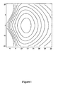
- Fig. 1 is a plot of the potential contours for a specific trapping configuration of a circular electrode.
- a 10 ⁇ m radius spot was chosen and had a DC voltage of -1V applied to it with respect to the earth plane.
- the value of the scaling parameter k was chosen to be 100.
- the horizontal ordinate is the perpendicular distance from the electrode plane and the vertical ordinate the radial distance from the symmetry axis, both in ⁇ m.
- the distance of the trap centre from the surface and the curvature at the bottom of the trap can be changed by changing the value of k .
- k the value of k
- particles of a given mass will be trapped at a point more distant from the plane of the electrode.
- k is dependent on a particle's mass, it follows that, for a given value of k , particles of heavier mass will lie closer to the plane of the electrode.
- the curvature of the bottom of the potential well changes, resulting in a larger sized and differently shaped trapping region. Note that this change in the trapping region is distinct from the change in trapping region brought about by funnelling techniques disclosed below, where the shape of the trapping region remains constant.
- the ion will remain trapped in the trapping region provided the adiabaticity parameter is small enough.
- this parameter must have a value of less than 0.3 for stable trapping. Tests indicate this parameter will have a value of about 0.05 near the minimum of the effective potential so the trapping is expected to be stable. Further numerical tests can be made to verify this assertion and to determine the volume over which stable trapping occurs.
- This principle is not restricted to a simple circular trapping electrode.
- a matrix of electrodes could be fabricated.
- the voltages applied to the various electrodes can then be chosen to manipulate particles in a number of ways, some of which are illustrated below.
- the voltages applied to the various electrodes in a planar array could be chosen for example so that all of those lying inside a given region are biased with an appropriate DC voltage and an AC voltage with the remaining electrodes being biased to zero volts.
- Gradually changing the location of the region inside which the biased electrodes reside i.e. changing electrodes successively from being biased to being at earth and the other way in a systematic fashion) corresponds to moving the trap location across the surface, effectively creating a particle conveyor belt.
- the electrodes can act as a funnel, the voltages being varied so as to bring trapped particles from a wide area to be concentrated in a central region.
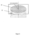
- FIG. 2 An example of an electrode configuration that can act as a funnel is shown in Fig. 2.
- a series of concentric electrodes 10 is provided, which initially all have the same AC and DC voltages applied. They are surrounded by a large earth plane 12.
- the system looks like a spot-trap, with a diameter equal to D1, and k set to a particular value.
- the outer electrode would be set to 0V (making it seem like part of the earth plane), whilst the waveform applied to the others would be changed to keep k at the same predetermined value (note l has changed because the diameter of the spot is equal D2).
- the effective potential now has the same form, but is slightly shrunk in comparison to the potential in the initial state.
- successive electrodes are grounded from the outside in, always keeping k constant, until a final state is reached where the particle is trapped by the central electrode.
- An alternative way of funnelling a particle may be to provide the same electrode structure; but initially only have the outer few rings with voltages applied, with those inside being earthed. Then, moving successively from the outside, each electrode is set to zero while one more inner has voltages applied. Thus, the particles are again focussed in a central region.
- the innermost electrode can be provided with an aperture, which acts as an extraction hole.
- an aperture acts as an extraction hole.
- the particles are trapped closer to the surface of the electrodes.
- the potential ceases to act as a trapping potential.
- the trap breakss" and a trapped particle can escape.
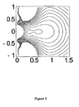
- the potential contours at this point are illustrated in Fig. 3.
- a biased extraction electrode can optionally be provided on the other side of the aperture.
- the two sides of the extraction region can be differentially pumped so that the buffer gas going through the aperture undergoes a supersonic expansion so that the beam of particles passing through the aperture is cooled.
- the abovementioned spot trap and conveyor belt configurations can be combined to provide manipulation of particles, where particles of differing mass or charge can be separated and treated differently.
- Fig. 4 shows a configuration where a series of conveyor electrodes 14 is provided, forming a conveyor 16, to which the voltages applied allows the conveyor 16 to transport particles from one trapping region to another.
- a spot trap electrode structure 18 is situated in the middle of the conveyor 16.
- the relative length scales of the conveyor electrodes 14 and the spot trap electrodes 18 are such that the conveyor electrodes 14 are much larger than the spot trap electrodes 18.
- a relatively light particle is trapped by the spot trap 18, it is trapped at such a height that, due to the local nature of the e-field and potential, it is more influenced by the potential of the conveyor 16 than the spot trap 18.
- the remaining heavier particles could be passed through an extraction hole, using the methods described above.
- the trap could initially be programmed to hold both the mass before and after an interaction. It then could be periodically programmed to have a lower value of k so the lighter (unchanged) particles rise up to be transported to a holding zone. The trap could then become part of a conveyor belt, perpendicular to the direction the lighter particles were moved. The heavier (changed) particles would then be transported away for further processing after which the lighter particles could be returned (possibly with others added) to the interaction region.
- the value of the scaling parameter k can be decreased such that the particles are lowered towards the electrode surface to interact with other particles deposited there. The value of k can then be increased again so that the product particles, and any unchanged particles can be raised up.
- printed circuit board technology can be used to construct the electrode arrays.
- the proximity of adjacent electrodes is limited by cross talk effect, but the nature of the interactions should be such that useful devices can be constructed for the transportation of various particles, such as, for example, ions or electrons.
- the above concepts have a wide range of potential applications.
- the techniques above may be used to enable miniaturisation and parallelisation of current techniques for frequency standards, quantum computation, quantum encryption and material analysis.
- the electrodes of an apparatus which are connected to an appropriate power supply, will normally be contained within a sealable chamber, and a gas pump is provided to introduce and extract gas in order to vary the pressure and control the quality of vacuum provided in the chamber.
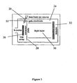
- Fig. 5 shows an apparatus that uses the techniques of the present invention, which is particularly intended to be used with biomolecular ions.
- Ions 20 are introduced into a chamber 24.
- Optional gate electrodes 22 are used to control the introduction of the ions 20.
- the ions 20 are used to seed an array of trap electrodes 26.
- a pump and gas inlet valve (not shown) control the introduction and extraction of a background buffer gas, to control the vacuum provided by the chamber 24.
- the voltages applied to the array 26 can be varied to manipulate ions 20, as described above.
- the trapping voltages can be switched off and an extraction voltage can be applied to an extraction plate 28 to accelerate the ions 20 through a flight tube 30 towards a position-sensitive detector 32.
- the ions 20 may undergo several collisions in the flight tube 30 these collisions will be brief and with the much lighter buffer gas partners. Accordingly these collisions should not destroy the positional or time-of-flight information.
- Time-of flight will be used to distinguish genuinely trapped or guided ions 20 from background ions so the time-gated image on the position-sensitive detector 32 corresponds to a snap-shot of the ion 20 locations just prior to the application of the extraction voltage.
- trapped ions have a thermal energy distribution that means they will have a finite chance of escaping, much as a water molecule has a chance of evaporating from a liquid below the boiling point.
- trapped particle escapes, it passes through the aperture.
- the voltages are varied, this shall occur slightly before the normally expected transmission time of that particular particle.
- the times when a particle may escape outside of these transmission times will depend on the values and rate of changes of the amplitude, waveform, and frequency of the voltages applied.
- the mass of the particle can be determined by correlating the time of passage through the aperture with the state of the trap at that time.
- the high collision frequency limit (useful for material processing and working with Biomolecules) and the collisionless limit (useful for quantum computation and encryption).
- the ions will rapidly become thermalised through collisions with background gas and one another.
- This background can be a rare gas buffer so no unwanted chemical reactions occur, or it could be, for example, water to investigate hydration of biomolecules.
- a rare gas buffer can easily be cooled to liquid N2 temperature when the characteristic energy associated with each degree of freedom will be about 3meV so the trapped ions will lie inside the trapping region, which is seen as the innermost contour of Fig. 1.
- the motion of a single ion can be approximated by a superposition of harmonic motions, which may be coupled.
- Another device that can be constructed using the principles of the invention is a single reconfigurable trap. This can be a few centimetres across, with circular electrodes centred about an extraction region consisting of a small aperture with the trap system to one side and a biased extraction electrode to the other side.
- the effective potential takes the form shown in Fig. 1.
- the effective potential contours are chosen so that the innermost contour corresponds to room temperature, compared to the minimum.
- the trap will be gradually reconfigured so that the length scale gradually reduces from about 3cm to 50 ⁇ m, so all of the ions trapped in the potential are gathered into a successively smaller volume, similar to a deflating balloon.
- the trapping nature will then be changed so that the ions are free to move towards the extraction region, centred at the origin.
- the potential will take the form shown in Fig. 3 (note change in z-axis), when the trapped ions will escape through the extraction region.
- the two sides of the extraction region can be differentially pumped so the buffer gas going through the aperture will undergo a supersonic expansion giving further cooling to the beam of biomolecular ions.
- the resultant pulsed source of cold biomolecular ions will be ideal for investigating their reactive scattering behaviour, hence creating a new and topical research field.
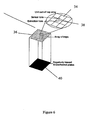
- An array of traps 34 forms a planar electrode structure 36 and is loaded with a specific molecular ion ( A + ) chosen to be able to react associatively with a particular biomolecule or class of biomolecules ( B ).
- a + a specific molecular ion
- B a particular biomolecule or class of biomolecules
- a + relates to the specificity of the detector.
- a microchannel plate 40 is provided, the front surface of which is biased highly negatively to attract the positive ions.
- any suitable position sensitive charged particle detector may be used in place of a microchannel plate.
- the trap configuration is arranged so that the product ion, being more massive falls towards the electrode surface 36 eventually being swept through due to a field penetrating through one of an array of small holes 38.
- This penetrating field occurs as a natural consequence of biasing the front surface of the microchannel plates 40 highly negative. Note that the same effect could be achieved by having the back face of the electrode array being negatively charged.
- the ion is then accelerated from the hole 38 towards a microchannel plate 40, which will be the front-end of a traditional position sensitive detector (something akin to an image intensifier).
- the resultant detection event provides a record of the position of the biomolecule prior to the interaction.
- time-of-flight information can be used to determine the mass of the product ion and hence determine the mass of A + as well as the class of molecules to which it belongs.
- a bespoke CAD/simulation package can also be provided to aid in the design of arrays to trap or guide charged particles.
- the motion of trapped ions can in principle be solved exactly through solution of Maxwell's equations for the fields and Newton's equations for the motion of the ions. However, this might be computationally intractable for the scale of problems envisaged.
- the properties of the trapping or guiding arrays will be deduced by solving the dynamics of the trapped ions at various levels of approximation ranging from full explicit solution of the motion of trapped ions coupled to a Monte-Carlo simulation for collisions with the buffer gas (computationally expensive) to simply calculating the effective trapping potential averaged over a particular 'trapping sequence' of applied voltages and then using statistical distributions and friction models for the ions subject to this effective potential (computationally cheap).
- Control of the program will be achieved through a visual interface, leading to a bespoke CAD/simulation program for ion trap/guide arrays, which can be made available to researchers in the field, and can act over an array of PC's acting as a parallel computer. Both the solution of Laplace's equation and the calculation of trajectories are amenable to parallel computation.
- the charged particles may comprise ions, electrons, or any other suitable charged particles.
- the fabrication of the electrode arrays may be by any suitable means, of which printed circuit board technology, lithographic methods, and focussed ion beam methods are examples only.
- electrodes in each embodiment may take any suitable shape, and the examples given should not be taken as limiting these to any particular shape, however only within the scope defined by the claims.
- a funnel configuration could be implemented by means of a series of concentric circular electrodes. These electrodes could be square, or any other suitable shape.
- the voltages applied to the electrodes may take any suitable form, and can be modulated before being sent to the electrodes, however only within the scope defined by the claims.
- the voltages could be square waves to enable digital logic techniques to be used when processing the information.
- the voltages applied to the electrodes can be of appropriate polarity to attract or repel specific particles.
- the microchannel plate is biased negatively. However, it could be charged positively to attract negative particles.
Landscapes
- Chemical & Material Sciences (AREA)
- Analytical Chemistry (AREA)
- Physical Or Chemical Processes And Apparatus (AREA)
- Medicines Containing Material From Animals Or Micro-Organisms (AREA)
- Electrostatic Separation (AREA)
- Silicon Compounds (AREA)
- Analysing Materials By The Use Of Radiation (AREA)
- Pharmaceuticals Containing Other Organic And Inorganic Compounds (AREA)
Claims (80)
- Gerät zum Beeinflussen des Phasenraums von mindestens einem geladenen Teilchen, wobei es eine Vielzahl von Elektroden (10, 14, 26, 36) beinhaltet, welche auf einer Oberfläche platziert sind und mit einer Stromversorgung verbunden sind, die fähig ist, sowohl eine Wechselstromspannung als auch eine Gleichstromspannung anzulegen, um ein Potential zu bilden, welches einer Seite der Oberfläche der Elektroden einen Bereich der Phasenraumbeeinflussung bereitstellt, wobei die Elektroden (10, 14, 26, 36) kein geladenes Teil umgeben, dessen Phasenraum bei Gebrauch beeinflusst wird, und dadurch gekennzeichnet, dass: die Elektroden (10, 14, 26, 36) in einer im Wesentlichen planaren Anordnung platziert sind, so dass sich das mindestens eine Teilchen an einer Seite der Anordnung befindet.
- Gerät gemäß Anspruch 1, das ferner ein Mittel zur Druckregelung beinhaltet, um den Druck des Raums, welcher die Elektroden (10, 14, 26, 36) umgibt, zu regeln.
- Gerät gemäß Anspruch 2, wobei das Mittel zur Druckregelung eine siegelbare Kammer und ein Gaspumpenmittel, das fähig ist, Gase in die Kammer einzuführen und aus ihr abzusaugen, beinhaltet.
- Gerät gemäß einem der Ansprüche 1-3, wobei die Stromversorgung bedient werden kann, um die Wechselstrom- und die Gleichstromspannung, welche angelegt werden, zu variieren.
- Gerät gemäß einem der vorhergehenden Ansprüche, wobei die Stromversorgung bedient werden kann, um die Amplitude, die Wellenform und die Frequenz der Wechselstromspannung individuell zu verändern, und bedient werden kann, um die Stärke der Gleichstromspannung zu verändern.
- Gerät gemäß einem der vorhergehenden Ansprüche, wobei das Potential ein effektives Potential ist.
- Gerät gemäß einem der vorhergehenden Ansprüche, wobei der Bereich der Phasenraumbeeinflussung einen Bereich zum Einfangen der Teilchen beinhaltet, wobei ein Teilchen in eine bestimmte räumliche Fläche gezwungen wird.
- Gerät gemäß einem der vorhergehenden Ansprüche, wobei der Bereich der Phasenraumbeeinflussung einen Bereich zur Führung der Teilchen beinhaltet, wobei ein Bewegungsablauf der Teilchen durch mindestens einen Freiheitsgrad eingeschränkt ist.
- Gerät gemäß einem der vorhergehenden Ansprüche, wobei die Spannungen, welche an die angrenzende erste und zweite Gruppe von Elektroden (10, 14, 26, 36) der planaren Anordnung von Elektroden angelegt werden, variiert werden können, so dass das mindestens eine Teilchen von einem Bereich zum Einfangen der Teilchen, welcher von der ersten Gruppe von Elektroden (10, 14, 26, 36) bereitgestellt wird, zu einem Bereich zum Einfangen der Teilchen, welcher von der zweiten Gruppe von Elektroden (10, 14, 26, 36) bereitgestellt wird, bewegt wird.
- Gerät gemäß Anspruch 9, wobei mindestens ein Teilchen von einem ersten Bereich zum Einfangen, welcher von der ersten Gruppe von Elektroden (10, 14, 26, 36) bereitgestellt wird, zu einem zweiten Bereich zum Einfangen, welcher von der zweiten Gruppe von Elektroden (10, 14, 26, 36) bereitgestellt wird, bewegt werden kann, wobei die Spannungen, welche an die Gruppen von Elektroden (10, 14, 26, 36) angelegt werden, von einer anfänglichen in eine dazwischen liegende und dann in eine endgültige Konfiguration geändert werden können, und wobei;
bei einer anfänglichen Konfiguration die erste Gruppe von Elektroden (10, 14, 26, 36) auf eine Haltespannung vorgespannt wird, um einen ersten Bereich zum Einfangen der Teilchen zu bilden, um mindestens ein Teilchen darin einzufangen, und die angrenzende zweite Gruppe von Elektroden (10, 14, 26, 36) auf null Volt vorgespannt wird;
bei einer dazwischen liegenden Konfiguration beide Gruppen von Elektroden (10, 14, 26, 36) auf die Haltespannung vorgespannt werden, um einen ineinander übergehenden Bereich zum Einfangen der Teilchen zu bilden, welcher das mindestens eine Teilchen einfängt;
bei einer endgültigen Konfiguration die erste Gruppe von Elektroden (10, 14, 26, 36) auf null Volt vorgespannt wird und die zweite Gruppe von Elektroden (10, 14, 26, 36) auf die Haltespannung vorgespannt wird, um einen zweiten Bereich zum Einfangen der Teilchen zu bilden, welcher das mindestens eine Teilchen einfängt. - Gerät gemäß Anspruch 10, wobei der Prozess des Bewegens von mindestens einem Teilchen von dem ersten Bereich zum Einfangen, welcher von der ersten Gruppe von Elektroden (10, 14, 26, 36) bereitgestellt wird, zu dem zweiten Bereich zum Einfangen, welcher von der zweiten Gruppe von Elektroden (10, 14, 26, 36) bereitgestellt wird, wiederholt werden kann, um das mindestens eine Teilchen entlang eines ausgewählten Wegs auf der planaren Anordnung zu bewegen.
- Gerät gemäß Anspruch 11, wobei die planare Anordnung unter Verwendung von Leiterplattentechnik, lithographischer Technik oder fokussierter lonenstrahltechnik gebildet wird.
- Gerät gemäß einem der Ansprüche 1-9, wobei die Vielzahl von Elektroden in einer Reihe von Elektroden (10, 14, 26, 36) bereitgestellt wird, wobei die Spannungen, welche an sie angelegt werden, geregelt werden können, so dass das mindestens eine Teilchen von einem ersten Bereich zum Einfangen der Teilchen zu einem zweiten Bereich zum Einfangen der Teilchen bewegt werden kann, wobei der erste Bereich zum Einfangen beträchtlicher als der zweite Bereich zum Einfangen ist.
- Gerät gemäß Anspruch 13, wobei die Spannungen, welche an die Elektroden (10, 14, 26, 36) angelegt werden, geregelt werden können, so dass das mindestens eine Teilchen zwischen einer Vielzahl von sukzessiv kleineren Bereichen zum Einfangen bewegt werden kann.
- Gerät gemäß Anspruch 13 oder Anspruch 14, wobei die Reihe von Elektroden (10, 14, 26, 36) eine Vielzahl von konzentrisch platzierten kreisförmigen Elektroden beinhaltet.
- Gerät gemäß Anspruch 15, wobei in einem anfänglichen Gebrauchszustand an jede Elektrode eine Kombination aus Wechselstrom- und Gleichstromspannung angelegt wird, so dass mindestens ein Teilchen in einem ersten Bereich zum Einfangen eingefangen wird;
wobei die Spannung, welche an die äußere Elektrode angelegt wird, geändert werden kann, so dass in einem dazwischen liegenden Gebrauchszustand das mindestens eine Teilchen in einem ersten dazwischen liegenden Bereich zum Einfangen, welcher von den übrigen inneren Elektroden (10, 14, 26, 36) bereitgestellt wird, eingefangen wird; und
wobei die Spannung, welche an die Elektrode, die an die äußere Elektrode angrenzt, angelegt wird, geändert werden kann, so dass in einem endgültigen Gebrauchszustand das mindestens eine Teilchen in einem zweiten Bereich zum Einfangen, welcher von der innersten Elektrode bereitgestellt wird, eingefangen wird. - Gerät gemäß Anspruch 16, wobei in den Übergängen von dem anfänglichen in den dazwischen liegenden und von dem dazwischen liegenden in den endgültigen Zustand die äußere bzw. die angrenzende Elektrode (10, 14, 26, 36) auf null Volt gestellt werden.
- Gerät gemäß Anspruch 16 oder Anspruch 17, wobei eine Vielzahl von Elektroden (10, 14, 26, 36) je einen weiteren dazwischen liegenden Bereich zum Einfangen bereitstellen kann, so dass zwischen dem anfänglichen Zustand und dem endgültigen Zustand das mindestens eine Teilchen durch eine Vielzahl von dazwischen liegenden Zuständen geht, wobei es in sukzessiv kleineren dazwischen liegenden Bereichen zum Einfangen eingefangen wird.
- Gerät gemäß einem der Ansprüche 13-15, wobei an jede Elektrode unterschiedliche Spannungen angelegt werden können, so dass in einem anfänglichen Zustand an eine äußerste Elektrode eine erste Kombination aus Wechselstrom- und Gleichstromspannung angelegt werden kann und eine Hintergrundspannung an die übrigen Elektroden (10, 14, 26, 36) angelegt werden kann, so dass in einem anfänglichen Zustand mindestens ein Teilchen in einem ersten Bereich zum Einfangen eingefangen wird;
und wobei: die Elektrode, die an die äußere Elektrode angrenzt, auf die erste Kombination aus Spannungen gestellt werden kann und die Hintergrundspannung an die äußere Elektrode angelegt werden kann, so dass in einem dazwischen liegenden Zustand das mindestens eine Teilchen in einem ersten dazwischen liegenden Bereich zum Einfangen eingefangen wird; und
wobei: die innerste Elektrode auf die erste Kombination aus Spannungen gestellt werden kann und die Hintergrundspannung an die angrenzende Elektrode angelegt werden kann, so dass in einem endgültigen Zustand das mindestens eine Teilchen in einem zweiten Bereich zum Einfangen eingefangen wird. - Gerät gemäß Anspruch 19, wobei die Hintergrundspannung null Volt beträgt.
- Gerät gemäß Anspruch 19 oder Anspruch 20, wobei eine Vielzahl von Elektroden (10, 14, 26, 36) bereitgestellt wird, so dass zwischen dem anfänglichen Zustand und dem endgültigen Zustand das mindestens eine Teilchen durch eine Vielzahl von dazwischen liegenden Zuständen geht, wobei es in sukzessiv kleineren dazwischen liegenden Bereichen zum Einfangen eingefangen wird.
- Gerät gemäß einem der Ansprüche 15-21, wenn abhängig von Anspruch 15, wobei die innerste Elektrode mit einer Öffnung versehen ist; platziert, so dass:wenn das mindestens eine Teilchen in dem endgültigen Zustand ist, eine Spannung an die Öffnung angelegt wird, so dass das mindestens eine Teilchen durch die Öffnung gedrängt wird.
- Gerät gemäß Anspruch 22, wobei jede Seite der Öffnung differentiell gepumpt wird, so dass ein Gas, welches durch die Öffnung geht, einer Ultraschallexpansion unterzogen wird, um die Teilchen, welche durch die Öffnung gedrängt werden, abzukühlen.
- Gerät gemäß einem der vorhergehenden Ansprüche, wobei die Spannungen, welche an eine der Elektroden angelegt werden, so sind, dass ein Typ geladener Teilchen von einem anderen unterschieden werden kann.
- Gerät gemäß Anspruch 24, wobei unterschiedliche Typen geladener Teilchen bei unterschiedlichen Entfernungen senkrecht zu der Oberfläche der Elektroden eingefangen werden.
- Gerät gemäß Anspruch 25, wobei die Entfernung von der Ladung und/oder der Masse des geladenen Teilchens abhängt.
- Gerät gemäß Anspruch 26, wobei ein erster Typ geladener Teilchen bei einer ersten senkrechten Entfernung zu der Elektrode eingefangen wird, und ein zweiter Typ geladener Teilchen bei einer zweiten senkrechten Entfernung zu der Elektrode eingefangen wird, wobei die Masse des ersten geladenen Teilchens größer als die Masse des zweiten geladenen Teilchens ist und die zweite senkrechte Entfernung größer als die erste senkrechte Entfernung ist.
- Gerät gemäß Anspruch 27, wobei mindestens ein Teilchen, welches bei der zweiten senkrechten Entfernung eingefangen wird, dem Potential ausgesetzt wird, das durch eine Spannungsfolge, welche an eine zweite Gruppe von Elektroden (10, 14, 26, 36) angelegt wird, gebildet wird.
- Gerät gemäß Anspruch 28, wobei die Spannungsfolge, welche an die zweite Gruppe von Elektroden (10, 14, 26, 36) angelegt wird, so ist, dass sie das mindestens eine Teilchen entlang eines zuvor bestimmten Wegs von einem Bereich zum Einfangen zu einem anderen transportiert.
- Gerät gemäß Anspruch 28 oder Anspruch 29, wobei die Dimensionen der zweiten Gruppe von Elektroden (10, 14, 26, 36) ein viel beträchtlicheres Ausmaß als die Dimensionen der Elektrodenfalle aufweisen.
- Gerät gemäß einem der Ansprüche 24-30, wobei eine Öffnung auf einer Elektrode bereitgestellt wird, so dass der Typ Teilchen, welcher der Oberfläche der Elektrode am nächsten ist, durch die Öffnung gehen kann.
- Gerät gemäß Anspruch 31, wobei jede Seite der Öffnung differentiell gepumpt wird, so dass ein Gas, welches durch die Öffnung geht, einer Ultraschallexpansion ausgesetzt wird, um die Teilchen, welche durch die Öffnung gedrängt werden, abzukühlen.
- Gerät gemäß einem der vorhergehenden Ansprüche, wobei die Spannungen, welche an eine der Elektroden angelegt werden, geändert werden können, so dass sich ein eingefangenes Teilchen in einer Richtung, welche zu der Ebene der Elektrode senkrecht verläuft, bewegt.
- Gerät gemäß Anspruch 33, wobei mindestens ein eingefangenes Teilchen auf einen Bereich herabgesetzt werden kann, wo es mit mindestens einem anderen Teilchen in Wechselwirkung stehen wird; und
wobei die Teilchen, die aus der Wechselwirkung resultieren, dann wieder heraufgesetzt werden können, zusammen mit Teilchen, die nicht in Wechselwirkung standen. - Gerät gemäß Anspruch 33 oder Anspruch 34, wobei die Elektrode mit einer Öffnung gebildet ist und die angelegte Spannung geändert werden kann, um ein Teilchen nahe an die Öffnung zu bringen; und
wobei eine Spannung an die Öffnung angelegt wird, so dass das Teilchen durch die Öffnung gedrängt wird. - Gerät gemäß Anspruch 35, wobei jede Seite der Öffnung differentiell gepumpt wird, so dass ein Gas, welches durch die Öffnung geht, einer Ultraschallexpansion ausgesetzt wird, um die Teilchen, welche durch die Öffnung gedrängt werden, abzukühlen.
- Gerät gemäß einem der Ansprüche 33-36, wobei die Spannungen, welche an die Anordnung von Elektroden (10, 14, 26, 36) angelegt wird, einen ersten Typ Teilchen einfangen, welcher mit einem zweiten Typ Teilchen in Wechselwirkung stehen kann, um ein reagierendes Teilchen zu bilden, das auf den Boden einer Falle fällt und durch ein Extraktionsloch weggetragen wird.
- Gerät gemäß Anspruch 37, wobei die Anordnung von Elektroden (10, 14, 26, 36) ferner mindestens eine Öffnung für die Extraktion eingefangener Teilchen beinhaltet.
- Gerät gemäß Anspruch 38, wobei jede Elektrode eine Öffnung beinhaltet.
- Gerät gemäß Anspruch 39, wobei das reagierende Teilchen durch ein Potential beschleunigt und erfasst wird, so dass die Position des ursprünglichen ersten Typs Teilchen erfasst werden kann.
- Ein Verfahren zum Beeinflussen des Phasenraums von mindestens einem geladenen Teilchen, wobei eine Kombination aus Wechselstrom- und Gleichstromspannung, welche an eine Vielzahl von Elektroden (10, 14, 26, 36) angelegt wird, ein Potential bildet, das einen Bereich der Phasenraumbeeinflussung bereitstellt, und wobei die Elektroden (10, 14, 26, 36) kein geladenes Teilchen umgeben, dessen Phasenraum bei Gebrauch beeinflusst wird, dadurch gekennzeichnet, dass: die Elektroden (10, 14, 26, 36) in einer im Wesentlichen planaren Anordnung platziert sind, so dass sich das mindestens eine Teilchen an einer Seite der Anordnung befindet.
- Verfahren gemäß Anspruch 41, das ferner den Schritt des Regelns des Drucks des Raums, welcher die Elektroden (10, 14, 26, 36) umgibt, beinhaltet.
- Verfahren gemäß Anspruch 42, wobei das Mittel zur Druckregelung eine siegelbare Kammer und ein Gaspumpenmittel, das fähig ist, Gase in die Kammer einzuführen und aus ihr abzusaugen, beinhaltet.
- Verfahren gemäß einem der Ansprüche 41-43, wobei die Stromversorgung bedient werden kann, um die Wechselstrom- und die Gleichstromspannung, welche angelegt werden, zu variieren.
- Verfahren gemäß einem der Ansprüche 41-44, wobei die Stromversorgung bedient werden kann, um die Amplitude, die Wellenform und die Frequenz der Wechselstromspannung individuell zu verändern und bedient werden kann, um die Stärke der Gleichstromspannung zu verändern.
- Verfahren gemäß einem der Ansprüche 41-45, wobei das Potential ein effektives Potential ist.
- Verfahren gemäß einem der Ansprüche 41-46, wobei der Bereich der Phasenraumbeeinflussung einen Bereich zum Einfangen der Teilchen beinhaltet, wobei ein Teilchen in eine bestimmte räumliche Fläche gezwungen wird.
- Verfahren gemäß einem der Ansprüche 41-47, wobei der Bereich der Phasenraumbeeinflussung einen Bereich zur Führung der Teilchen beinhaltet, wobei ein Bewegungsablauf der Teilchen durch mindestens einen Freiheitsgrad eingeschränkt ist.
- Verfahren gemäß einem der Ansprüche 41-48, wobei die Spannungen, welche an die angrenzende erste und zweite Gruppe von Elektroden (10, 14, 26, 36) der planaren Anordnung von Elektroden angelegt werden, variiert werden können, so dass das mindestens eine Teilchen von dem Bereich zum Einfangen der Teilchen, welcher von der ersten Gruppe von Elektroden (10, 14, 26, 36) bereitgestellt wird, zu dem Bereich zum Einfangen der Teilchen, welcher von der zweiten Gruppe von Elektroden (10, 14, 26, 36) bereitgestellt wird, bewegt werden kann.
- Verfahren gemäß Anspruch 49, wobei mindestens ein Teilchen von einem ersten Bereich zum Einfangen, welcher von der ersten Gruppe von Elektroden (10, 14, 26, 36) bereitgestellt wird, zu einem zweiten Bereich zum Einfangen, welcher von der zweiten Gruppe von Elektroden (10, 14, 26, 36) bereitgestellt wird, bewegt wird, wobei die Spannungen, welche an die Gruppen von Elektroden (10, 14, 26, 36) angelegt werden, von einer anfänglichen in eine dazwischen liegende und dann in eine endgültige Konfiguration geändert werden, und wobei;
bei einer anfänglichen Konfiguration die erste Gruppe von Elektroden (10, 14, 26, 36) auf eine Haltespannung vorgespannt wird, um einen ersten Bereich zum Einfangen der Teilchen zu bilden, um mindestens ein Teilchen darin einzufangen, und die angrenzende zweite Gruppe von Elektroden (10, 14, 26, 36) auf null Volt vorgespannt wird;
bei einer dazwischen liegenden Konfiguration beide Gruppen von Elektroden (10, 14, 26, 36) auf eine Haltespannung vorgespannt werden, um einen ineinander übergehenden Bereich zum Einfangen der Teilchen zu bilden, welcher das mindestens eine Teilchen einfängt;
bei einer endgültigen Konfiguration die erste Gruppe von Elektroden (10, 14, 26, 36) auf null Volt vorgespannt wird und die zweite Gruppe von Elektroden (10, 14, 26, 36) auf die Haltespannung vorgespannt wird, um einen zweiten Bereich zum Einfangen der Teilchen zu bilden, welcher das mindestens eine Teilchen einfängt. - Verfahren gemäß Anspruch 50, wobei der Prozess des Bewegens von mindestens einem Teilchen von dem ersten Bereich zum Einfangen, welcher von einer ersten Gruppe von Elektroden (10, 14, 26, 36) bereitgestellt wird, zu dem zweiten Bereich zum Einfangen, welcher von einer zweiten Gruppe von Elektroden (10, 14, 26, 36) bereitgestellt wird, wiederholt werden kann, um das mindestens eine Teilchen entlang eines ausgewählten Wegs auf der planaren Anordnung zu bewegen.
- Verfahren gemäß Anspruch 51, wobei die planare Anordnung unter Verwendung von Leiterplattentechnik, lithographischer Technik oder fokussierter lonenstrahltechnik gebildet wird.
- Verfahren gemäß einem der Ansprüche 41-52, wobei die Vielzahl von Elektroden in einer Reihe von Elektroden (10, 14, 26, 36) bereitgestellt wird, wobei die Spannungen, welche an sie angelegt werden, geregelt werden können, so dass das mindestens eine Teilchen von einem ersten Bereich zum Einfangen der Teilchen zu einem zweiten Bereich zum Einfangen der Teilchen bewegt werden kann, wobei der erste Bereich zum Einfangen beträchtlicher als der zweite Bereich zum Einfangen ist.
- Verfahren gemäß Anspruch 53, wobei die Spannungen, welche an die Elektroden (10, 14, 26, 36) angelegt werden, geregelt werden können, so dass das mindestens eine Teilchen zwischen einer Vielzahl von sukzessiv kleineren Bereichen zum Einfangen bewegt werden kann.
- Verfahren gemäß Anspruch 53 oder Anspruch 54, wobei die Reihe von Elektroden (10, 14, 26, 36) eine Vielzahl von konzentrisch platzierten kreisförmigen Elektroden (10, 14, 26, 36) beinhaltet.
- Verfahren gemäß Anspruch 55, wobei in einem anfänglichen Zustand an jede Elektrode eine Kombination aus Wechselstrom- und Gleichstromspannung angelegt wird, so dass mindestens ein Teilchen in einem ersten Bereich zum Einfangen eingefangen wird;
wobei die Spannung, welche an die äußere Elektrode angelegt wird, geändert wird, so dass in einem dazwischen liegenden Zustand das mindestens eine Teilchen in einem ersten dazwischen liegenden Bereich zum Einfangen, welcher von den übrigen inneren Elektroden (10, 14, 26, 36) bereitgestellt wird, eingefangen wird; und
wobei die Spannung, welche an die Elektrode, die an die äußere Elektrode angrenzt, angelegt wird, geändert wird, so dass in einem endgültigen Zustand das mindestens eine Teilchen in einem zweiten Bereich zum Einfangen, welcher von der innersten Elektrode bereitgestellt wird, eingefangen wird. - Verfahren gemäß Anspruch 56, wobei in den Übergängen von dem anfänglichen in den dazwischen liegenden und von dem dazwischen liegenden in den endgültigen Zustand die äußere bzw. die angrenzende Elektrode (10, 14, 26, 36) auf null Volt gestellt werden.
- Verfahren gemäß Anspruch 56 oder Anspruch 57, wobei eine Vielzahl von Elektroden (10, 14, 26, 36) je einen weiteren dazwischen liegenden Bereich zum Einfangen bereitstellt, so dass zwischen dem anfänglichen Zustand und dem endgültigen Zustand das mindestens eine Teilchen durch eine Vielzahl von dazwischen liegenden Zustände geht, wobei es in sukzessiv kleineren dazwischen liegenden Bereichen zum Einfangen eingefangen wird.
- Verfahren gemäß einem der Ansprüche 53-55, wobei in einem anfänglichen Zustand an eine äußerste Elektrode eine erste Kombination aus Wechselstrom- und Gleichstromspannung angelegt wird und eine Hintergrundspannung an die übrigen Elektroden (10, 14, 26, 36) angelegt wird, so dass in einem anfänglichen Zustand mindestens ein Teilchen in einem ersten Bereich zum Einfangen eingefangen wird;
wobei die Elektrode, die an die äußere Elektrode angrenzt, auf die erste Kombination aus Spannungen gestellt wird und die Hintergrundspannung an die äußere Elektrode angelegt wird, so dass in einem dazwischen liegenden Zustand das mindestens eine Teilchen in einem ersten dazwischen liegenden Bereich zum Einfangen eingefangen wird; und
wobei die innerste Elektrode auf die erste Kombination aus Spannungen gestellt wird und die Hintergrundspannung an die angrenzende Elektrode angelegt wird, so dass in einem endgültigen Zustand das mindestens eine Teilchen in einem zweiten Bereich zum Einfangen eingefangen wird. - Verfahren gemäß Anspruch 59, wobei die Hintergrundspannung null Volt beträgt.
- Verfahren gemäß Anspruch 59 oder Anspruch 60, wobei eine Vielzahl von Elektroden (10, 14, 26, 36) bereitgestellt wird, so dass zwischen dem anfänglichen Zustand und dem endgültigen Zustand das mindestens eine Teilchen durch eine Vielzahl von dazwischen liegenden Zuständen geht, wobei es in sukzessiv kleineren dazwischen liegenden Bereichen zum Einfangen eingefangen wird.
- Verfahren gemäß einem der Ansprüche 55-61, wenn abhängig von Anspruch 55, wobei die innerste Elektrode mit einer Öffnung versehen ist; und
wenn das mindestens eine Teilchen in dem endgültigen Zustand ist, eine Spannung an die Öffnung angelegt wird, so dass das mindestens eine Teilchen durch die Öffnung gedrängt wird. - Verfahren gemäß Anspruch 62, wobei jede Seite der Öffnung differentiell gepumpt wird, so dass ein Gas, welches durch die Öffnung geht, einer Ultraschallexpansion ausgesetzt wird, um die Teilchen, welche durch die Öffnung gedrängt werden, abzukühlen.
- Verfahren gemäß einem der Ansprüche 41-63, wobei die Spannungen, welche an eine der Elektroden angelegt werden, so sind, dass ein Typ geladener Teilchen von einem anderen unterschieden werden kann.
- Verfahren gemäß Anspruch 64, wobei unterschiedliche Typen geladener Teilchen bei unterschiedlichen Entfernungen senkrecht zu der Oberfläche der Elektroden eingefangen werden.
- Verfahren gemäß Anspruch 65, wobei die Entfernung von der Ladung und/oder der Masse des geladenen Teilchens abhängt.
- Verfahren gemäß Anspruch 66, wobei ein erster Typ geladener Teilchen bei einer ersten senkrechten Entfernung zu der Elektrode eingefangen wird und ein zweiter Typ geladener Teilchen bei einer zweiten senkrechten Entfernung zu der Elektrode eingefangen wird, wobei die Masse des ersten geladenen Teilchens größer als die Masse des zweiten geladenen Teilchens ist und die zweite senkrechte Entfernung größer als die erste senkrechte Entfernung ist.
- Verfahren gemäß Anspruch 67, wobei mindestens ein Teilchen, welches bei der zweiten senkrechten Entfernung eingefangen wird, dem Potential ausgesetzt wird, das durch eine Spannungsfolge, welche an eine zweite Gruppe von Elektroden (10, 14, 26, 36) angelegt wird, gebildet wird.
- Verfahren gemäß Anspruch 68, wobei die Spannungsfolge, welche an die zweite Gruppe von Elektroden (10, 14, 26, 36) angelegt wird, so ist, dass sie das mindestens eine Teilchen entlang eines zuvor bestimmten Wegs von einem Bereich zum Einfangen zu einem anderen transportiert.
- Verfahren gemäß Anspruch 68 oder Anspruch 69, wobei die Dimensionen der zweiten Gruppe von Elektroden (10, 14, 26, 36) ein viel beträchtlicheres Ausmaß als die Dimensionen der Elektrodenfalle aufweisen.
- Verfahren gemäß einem der Ansprüche 64-70, wobei eine Öffnung auf einer Elektrode bereitgestellt wird, so dass der Typ Teilchen, welcher der Oberfläche der Elektrode am nächsten ist, durch die Öffnung gehen kann.
- Verfahren gemäß Anspruch 71, wobei jede Seite der Öffnung differentiell gepumpt wird, so dass ein Gas, welches durch die Öffnung geht, einer Ultraschallexpansion ausgesetzt wird, um die Teilchen, welche durch die Öffnung gedrängt werden, abzukühlen.
- Verfahren gemäß einem der Ansprüche 41-72, wobei die Spannungen, welche an eine der Elektroden angelegt werden, geändert werden können, so dass sich ein eingefangenes Teilchen in einer Richtung, welche zu der Ebene der Elektrode senkrecht verläuft, bewegt.
- Verfahren gemäß Anspruch 73, wobei mindestens ein eingefangenes Teilchen auf einen Bereich herabgesetzt werden kann, wo es mit mindestens einem anderen Teilchen in Wechselwirkung stehen wird; und
wobei die Teilchen, die aus der Wechselwirkung resultieren, dann wieder heraufgesetzt werden können, zusammen mit Teilchen, die nicht in Wechselwirkung standen. - Verfahren gemäß Anspruch 73 oder Anspruch 74, wobei die Elektrode mit einer Öffnung gebildet ist und die angelegte Spannung geändert werden kann, um ein Teilchen nahe an die Öffnung zu bringen; und
wobei eine Spannung an die Öffnung angelegt wird, so dass das Teilchen durch die Öffnung gedrängt wird. - Verfahren gemäß Anspruch 75, wobei jede Seite der Öffnung differentiell gepumpt wird, so dass ein Gas, welches durch die Öffnung geht, einer Ultraschallexpansion ausgesetzt wird, um die Teilchen, welche durch die Öffnung gedrängt werden, abzukühlen.
- Verfahren gemäß einem der Ansprüche 73-76, wobei die Spannungen, welche an die Anordnung von Elektroden (10, 14, 26, 36) angelegt werden, einen ersten Typ Teilchen einfangen, welcher mit einem zweiten Typ Teilchen in Wechselwirkung stehen kann, um ein reagierendes Teilchen zu bilden, das auf den Boden einer Falle fällt und durch ein Extraktionsloch weggetragen wird.
- Verfahren gemäß Anspruch 77, wobei die Anordnung von Elektroden (10, 14, 26, 36) ferner mindestens eine Öffnung für die Extraktion eingefangener Teilchen beinhaltet.
- Verfahren gemäß Anspruch 78, wobei jede Elektrode eine Öffnung beinhaltet.
- Verfahren gemäß Anspruch 79, wobei das reagierende Teilchen durch ein Potential beschleunigt und erfasst wird, so dass die Position des ursprünglichen ersten Typs Teilchen erfasst werden kann.
Applications Claiming Priority (3)
| Application Number | Priority Date | Filing Date | Title |
|---|---|---|---|
| GBGB0219872.9A GB0219872D0 (en) | 2002-08-27 | 2002-08-27 | Charged particle manipulation |
| GB0219872 | 2002-08-27 | ||
| PCT/GB2003/003683 WO2004021385A2 (en) | 2002-08-27 | 2003-08-22 | Charged particle manipulation |
Publications (2)
| Publication Number | Publication Date |
|---|---|
| EP1532647A2 EP1532647A2 (de) | 2005-05-25 |
| EP1532647B1 true EP1532647B1 (de) | 2007-07-25 |
Family
ID=9943004
Family Applications (1)
| Application Number | Title | Priority Date | Filing Date |
|---|---|---|---|
| EP03791010A Expired - Lifetime EP1532647B1 (de) | 2002-08-27 | 2003-08-22 | Beeinflussung geladener teilchen |
Country Status (9)
| Country | Link |
|---|---|
| US (1) | US20050199796A1 (de) |
| EP (1) | EP1532647B1 (de) |
| JP (1) | JP2005537471A (de) |
| CN (1) | CN1695218A (de) |
| AT (1) | ATE368295T1 (de) |
| AU (1) | AU2003259348A1 (de) |
| DE (1) | DE60315163T2 (de) |
| GB (1) | GB0219872D0 (de) |
| WO (1) | WO2004021385A2 (de) |
Families Citing this family (12)
| Publication number | Priority date | Publication date | Assignee | Title |
|---|---|---|---|---|
| GB2403591B (en) * | 2002-11-08 | 2005-09-14 | Micromass Ltd | Mass spectrometer |
| EP1759402B1 (de) * | 2004-05-21 | 2015-07-08 | Craig M. Whitehouse | Hf-oberflächen und hf-ionenführungen |
| CN1326191C (zh) * | 2004-06-04 | 2007-07-11 | 复旦大学 | 用印刷电路板构建的离子阱质量分析仪 |
| DK1859330T3 (da) | 2005-01-28 | 2012-10-15 | Univ Duke | Apparater og fremgangsmåder til håndtering af små dråber på et trykt kredsløbskort |
| GB0524972D0 (en) * | 2005-12-07 | 2006-01-18 | Micromass Ltd | Mass spectrometer |
| US20140193807A1 (en) | 2006-04-18 | 2014-07-10 | Advanced Liquid Logic, Inc. | Bead manipulation techniques |
| FR2907223B1 (fr) * | 2006-10-13 | 2009-04-03 | Areva Np Sas | Procede et dispositif de detection d'anomalies structurelles dans une particule spherique,notamment dans une particule de combustible nucleaire pour reacteurs a haute temperature ou tres haute temperature. |
| CN101675496B (zh) * | 2007-05-21 | 2013-01-02 | 株式会社岛津制作所 | 带电粒子凝聚装置 |
| WO2010014077A1 (en) | 2008-07-28 | 2010-02-04 | Leco Corporation | Method and apparatus for ion manipulation using mesh in a radio frequency field |
| US8552365B2 (en) * | 2009-05-11 | 2013-10-08 | Thermo Finnigan Llc | Ion population control in a mass spectrometer having mass-selective transfer optics |
| GB2506362B (en) | 2012-09-26 | 2015-09-23 | Thermo Fisher Scient Bremen | Improved ion guide |
| US20240249930A1 (en) | 2023-01-19 | 2024-07-25 | Thermo Fisher Scientific (Bremen) Gmbh | Ion Beam Focusing |
Citations (4)
| Publication number | Priority date | Publication date | Assignee | Title |
|---|---|---|---|---|
| GB2180687A (en) * | 1985-09-19 | 1987-04-01 | Bruker Franzen Analytik Gmbh | Method and apparatus for examining a gas mixture |
| EP0437085A2 (de) * | 1990-01-08 | 1991-07-17 | Wisconsin Alumni Research Foundation | Verfahren und Vorrichtung zur Ionenzyklotronresonanzspektrometrie mit Linearprädiktion |
| WO1998001012A1 (en) * | 1996-07-03 | 1998-01-08 | Tegal Corporation | Plasma etch reactor and method for emerging films |
| EP1505633A2 (de) * | 2001-06-25 | 2005-02-09 | Micromass UK Limited | Massenspektrometer. |
Family Cites Families (5)
| Publication number | Priority date | Publication date | Assignee | Title |
|---|---|---|---|---|
| US5015845A (en) * | 1990-06-01 | 1991-05-14 | Vestec Corporation | Electrospray method for mass spectrometry |
| US5206506A (en) * | 1991-02-12 | 1993-04-27 | Kirchner Nicholas J | Ion processing: control and analysis |
| DE4318872A1 (de) * | 1993-06-07 | 1994-12-08 | Moeller Hamburg Gmbh Co Kg | Doppelrohr für eine pneumatische Förderung |
| US6683301B2 (en) * | 2001-01-29 | 2004-01-27 | Analytica Of Branford, Inc. | Charged particle trapping in near-surface potential wells |
| EP1372828A4 (de) * | 2001-03-24 | 2008-10-29 | Aviva Biosciences Corp | Biochips mit ionentransporterfassungsstrukturen und verwendungsverfahren |
-
2002
- 2002-08-27 GB GBGB0219872.9A patent/GB0219872D0/en not_active Ceased
-
2003
- 2003-08-22 AT AT03791010T patent/ATE368295T1/de not_active IP Right Cessation
- 2003-08-22 WO PCT/GB2003/003683 patent/WO2004021385A2/en not_active Ceased
- 2003-08-22 DE DE60315163T patent/DE60315163T2/de not_active Expired - Fee Related
- 2003-08-22 JP JP2004532276A patent/JP2005537471A/ja active Pending
- 2003-08-22 EP EP03791010A patent/EP1532647B1/de not_active Expired - Lifetime
- 2003-08-22 CN CNA038246910A patent/CN1695218A/zh active Pending
- 2003-08-22 AU AU2003259348A patent/AU2003259348A1/en not_active Abandoned
- 2003-08-22 US US10/524,912 patent/US20050199796A1/en not_active Abandoned
Patent Citations (4)
| Publication number | Priority date | Publication date | Assignee | Title |
|---|---|---|---|---|
| GB2180687A (en) * | 1985-09-19 | 1987-04-01 | Bruker Franzen Analytik Gmbh | Method and apparatus for examining a gas mixture |
| EP0437085A2 (de) * | 1990-01-08 | 1991-07-17 | Wisconsin Alumni Research Foundation | Verfahren und Vorrichtung zur Ionenzyklotronresonanzspektrometrie mit Linearprädiktion |
| WO1998001012A1 (en) * | 1996-07-03 | 1998-01-08 | Tegal Corporation | Plasma etch reactor and method for emerging films |
| EP1505633A2 (de) * | 2001-06-25 | 2005-02-09 | Micromass UK Limited | Massenspektrometer. |
Also Published As
| Publication number | Publication date |
|---|---|
| DE60315163D1 (de) | 2007-09-06 |
| EP1532647A2 (de) | 2005-05-25 |
| AU2003259348A8 (en) | 2004-03-19 |
| ATE368295T1 (de) | 2007-08-15 |
| CN1695218A (zh) | 2005-11-09 |
| US20050199796A1 (en) | 2005-09-15 |
| WO2004021385A3 (en) | 2004-12-02 |
| GB0219872D0 (en) | 2002-10-02 |
| AU2003259348A1 (en) | 2004-03-19 |
| JP2005537471A (ja) | 2005-12-08 |
| DE60315163T2 (de) | 2008-04-10 |
| WO2004021385A2 (en) | 2004-03-11 |
Similar Documents
| Publication | Publication Date | Title |
|---|---|---|
| EP1532647B1 (de) | Beeinflussung geladener teilchen | |
| US10497552B2 (en) | Methods and systems for ion manipulation | |
| Passananti et al. | How well can we predict cluster fragmentation inside a mass spectrometer? | |
| Can et al. | Physics based metaheuristic algorithms for global optimization | |
| Alford et al. | Metal cluster ion cyclotron resonance. Combining supersonic metal cluster beam technology with FT-ICR | |
| Schwabe et al. | Simulating the dynamics of complex plasmas | |
| JPH05509437A (ja) | イオン処理:貯蔵、冷却および分析 | |
| EP1706890A2 (de) | Eingrenzung von positiv- und negativionen mit schnell oszillierenden elektrischen potentialen | |
| Mochalskyy et al. | Towards a realistic 3D simulation of the extraction region in ITER NBI relevant ion source | |
| WO2004109741A2 (en) | Ion extraction | |
| Lancuba et al. | Electrostatic trapping and in situ detection of Rydberg atoms above chip-based transmission lines | |
| Biswas et al. | Simulation of a recoil mass spectrometer for measurement of differential quasi-elastic scattering cross sections: A semi-microscopic Monte Carlo code | |
| Lapenta et al. | Simulation of dust particle dynamics for electrode design in plasma discharges | |
| Maxeiner et al. | Simulation of ion beam scattering in a gas stripper | |
| Hagelaar | Modelling methods for low-temperature plasmas | |
| Macucci et al. | Status and perspectives of nanoscale device modelling | |
| Killian et al. | Ultracold neutral plasmas | |
| Smith | A square-wave-driven radiofrequency quadrupole cooler and buncher for TITAN | |
| Chiarinelli et al. | Ion optics simulation of an ion beam setup coupled to an electrospray ionization source, strengths, and limitations | |
| Lequette | Numerical model of the PEGASES spacecraft thruster | |
| Song et al. | Numerical Analysis and Quantification of Transfer Efficiency Coupled with Capillary and Quadrupole Ion Guide in an API-MS System | |
| Danielson et al. | New plasma tools for antimatter science | |
| Powis et al. | Scaling of spoke rotation frequency within a Penning discharge and code development updates | |
| Marti et al. | Ion wake-mediated dust interactions under PK-4 conditions: a generalized and compact potential formulation | |
| Hedlof et al. | Charged particle reflection by a planar artificially structured boundary with electrostatic plugging |
Legal Events
| Date | Code | Title | Description |
|---|---|---|---|
| PUAI | Public reference made under article 153(3) epc to a published international application that has entered the european phase |
Free format text: ORIGINAL CODE: 0009012 |
|
| 17P | Request for examination filed |
Effective date: 20050303 |
|
| AK | Designated contracting states |
Kind code of ref document: A2 Designated state(s): AT BE BG CH CY CZ DE DK EE ES FI FR GB GR HU IE IT LI LU MC NL PT RO SE SI SK TR |
|
| AX | Request for extension of the european patent |
Extension state: AL LT LV MK |
|
| 17Q | First examination report despatched |
Effective date: 20050624 |
|
| DAX | Request for extension of the european patent (deleted) | ||
| RIC1 | Information provided on ipc code assigned before grant |
Ipc: H01J 49/34 20060101AFI20061030BHEP |
|
| GRAP | Despatch of communication of intention to grant a patent |
Free format text: ORIGINAL CODE: EPIDOSNIGR1 |
|
| RIN1 | Information on inventor provided before grant (corrected) |
Inventor name: CURRELL, FREDERICK JOHN |
|
| GRAS | Grant fee paid |
Free format text: ORIGINAL CODE: EPIDOSNIGR3 |
|
| GRAA | (expected) grant |
Free format text: ORIGINAL CODE: 0009210 |
|
| AK | Designated contracting states |
Kind code of ref document: B1 Designated state(s): AT BE BG CH CY CZ DE DK EE ES FI FR GB GR HU IE IT LI LU MC NL PT RO SE SI SK TR |
|
| REG | Reference to a national code |
Ref country code: GB Ref legal event code: FG4D |
|
| REG | Reference to a national code |
Ref country code: CH Ref legal event code: EP |
|
| REG | Reference to a national code |
Ref country code: IE Ref legal event code: FG4D |
|
| REF | Corresponds to: |
Ref document number: 60315163 Country of ref document: DE Date of ref document: 20070906 Kind code of ref document: P |
|
| ET | Fr: translation filed | ||
| PG25 | Lapsed in a contracting state [announced via postgrant information from national office to epo] |
Ref country code: ES Free format text: LAPSE BECAUSE OF FAILURE TO SUBMIT A TRANSLATION OF THE DESCRIPTION OR TO PAY THE FEE WITHIN THE PRESCRIBED TIME-LIMIT Effective date: 20071105 Ref country code: PT Free format text: LAPSE BECAUSE OF FAILURE TO SUBMIT A TRANSLATION OF THE DESCRIPTION OR TO PAY THE FEE WITHIN THE PRESCRIBED TIME-LIMIT Effective date: 20071226 Ref country code: NL Free format text: LAPSE BECAUSE OF FAILURE TO SUBMIT A TRANSLATION OF THE DESCRIPTION OR TO PAY THE FEE WITHIN THE PRESCRIBED TIME-LIMIT Effective date: 20070725 Ref country code: BG Free format text: LAPSE BECAUSE OF FAILURE TO SUBMIT A TRANSLATION OF THE DESCRIPTION OR TO PAY THE FEE WITHIN THE PRESCRIBED TIME-LIMIT Effective date: 20071025 Ref country code: FI Free format text: LAPSE BECAUSE OF FAILURE TO SUBMIT A TRANSLATION OF THE DESCRIPTION OR TO PAY THE FEE WITHIN THE PRESCRIBED TIME-LIMIT Effective date: 20070725 |
|
| REG | Reference to a national code |
Ref country code: CH Ref legal event code: PL |
|
| NLV1 | Nl: lapsed or annulled due to failure to fulfill the requirements of art. 29p and 29m of the patents act | ||
| PG25 | Lapsed in a contracting state [announced via postgrant information from national office to epo] |
Ref country code: LI Free format text: LAPSE BECAUSE OF FAILURE TO SUBMIT A TRANSLATION OF THE DESCRIPTION OR TO PAY THE FEE WITHIN THE PRESCRIBED TIME-LIMIT Effective date: 20070725 Ref country code: CH Free format text: LAPSE BECAUSE OF FAILURE TO SUBMIT A TRANSLATION OF THE DESCRIPTION OR TO PAY THE FEE WITHIN THE PRESCRIBED TIME-LIMIT Effective date: 20070725 Ref country code: AT Free format text: LAPSE BECAUSE OF FAILURE TO SUBMIT A TRANSLATION OF THE DESCRIPTION OR TO PAY THE FEE WITHIN THE PRESCRIBED TIME-LIMIT Effective date: 20070725 |
|
| PG25 | Lapsed in a contracting state [announced via postgrant information from national office to epo] |
Ref country code: BE Free format text: LAPSE BECAUSE OF FAILURE TO SUBMIT A TRANSLATION OF THE DESCRIPTION OR TO PAY THE FEE WITHIN THE PRESCRIBED TIME-LIMIT Effective date: 20070725 |
|
| PG25 | Lapsed in a contracting state [announced via postgrant information from national office to epo] |
Ref country code: DK Free format text: LAPSE BECAUSE OF FAILURE TO SUBMIT A TRANSLATION OF THE DESCRIPTION OR TO PAY THE FEE WITHIN THE PRESCRIBED TIME-LIMIT Effective date: 20070725 Ref country code: MC Free format text: LAPSE BECAUSE OF NON-PAYMENT OF DUE FEES Effective date: 20070831 Ref country code: GR Free format text: LAPSE BECAUSE OF FAILURE TO SUBMIT A TRANSLATION OF THE DESCRIPTION OR TO PAY THE FEE WITHIN THE PRESCRIBED TIME-LIMIT Effective date: 20071026 |
|
| PG25 | Lapsed in a contracting state [announced via postgrant information from national office to epo] |
Ref country code: CZ Free format text: LAPSE BECAUSE OF FAILURE TO SUBMIT A TRANSLATION OF THE DESCRIPTION OR TO PAY THE FEE WITHIN THE PRESCRIBED TIME-LIMIT Effective date: 20070725 Ref country code: SK Free format text: LAPSE BECAUSE OF FAILURE TO SUBMIT A TRANSLATION OF THE DESCRIPTION OR TO PAY THE FEE WITHIN THE PRESCRIBED TIME-LIMIT Effective date: 20070725 |
|
| PLBE | No opposition filed within time limit |
Free format text: ORIGINAL CODE: 0009261 |
|
| STAA | Information on the status of an ep patent application or granted ep patent |
Free format text: STATUS: NO OPPOSITION FILED WITHIN TIME LIMIT |
|
| PG25 | Lapsed in a contracting state [announced via postgrant information from national office to epo] |
Ref country code: RO Free format text: LAPSE BECAUSE OF FAILURE TO SUBMIT A TRANSLATION OF THE DESCRIPTION OR TO PAY THE FEE WITHIN THE PRESCRIBED TIME-LIMIT Effective date: 20070725 Ref country code: SE Free format text: LAPSE BECAUSE OF FAILURE TO SUBMIT A TRANSLATION OF THE DESCRIPTION OR TO PAY THE FEE WITHIN THE PRESCRIBED TIME-LIMIT Effective date: 20071025 |
|
| 26N | No opposition filed |
Effective date: 20080428 |
|
| PG25 | Lapsed in a contracting state [announced via postgrant information from national office to epo] |
Ref country code: IE Free format text: LAPSE BECAUSE OF NON-PAYMENT OF DUE FEES Effective date: 20070822 |
|
| PGFP | Annual fee paid to national office [announced via postgrant information from national office to epo] |
Ref country code: DE Payment date: 20080829 Year of fee payment: 6 |
|
| PGFP | Annual fee paid to national office [announced via postgrant information from national office to epo] |
Ref country code: FR Payment date: 20080718 Year of fee payment: 6 |
|
| PGFP | Annual fee paid to national office [announced via postgrant information from national office to epo] |
Ref country code: GB Payment date: 20080722 Year of fee payment: 6 |
|
| PG25 | Lapsed in a contracting state [announced via postgrant information from national office to epo] |
Ref country code: EE Free format text: LAPSE BECAUSE OF FAILURE TO SUBMIT A TRANSLATION OF THE DESCRIPTION OR TO PAY THE FEE WITHIN THE PRESCRIBED TIME-LIMIT Effective date: 20070725 |
|
| PG25 | Lapsed in a contracting state [announced via postgrant information from national office to epo] |
Ref country code: SI Free format text: LAPSE BECAUSE OF FAILURE TO SUBMIT A TRANSLATION OF THE DESCRIPTION OR TO PAY THE FEE WITHIN THE PRESCRIBED TIME-LIMIT Effective date: 20070725 |
|
| PG25 | Lapsed in a contracting state [announced via postgrant information from national office to epo] |
Ref country code: CY Free format text: LAPSE BECAUSE OF FAILURE TO SUBMIT A TRANSLATION OF THE DESCRIPTION OR TO PAY THE FEE WITHIN THE PRESCRIBED TIME-LIMIT Effective date: 20070725 |
|
| PG25 | Lapsed in a contracting state [announced via postgrant information from national office to epo] |
Ref country code: LU Free format text: LAPSE BECAUSE OF NON-PAYMENT OF DUE FEES Effective date: 20070822 |
|
| PG25 | Lapsed in a contracting state [announced via postgrant information from national office to epo] |
Ref country code: HU Free format text: LAPSE BECAUSE OF FAILURE TO SUBMIT A TRANSLATION OF THE DESCRIPTION OR TO PAY THE FEE WITHIN THE PRESCRIBED TIME-LIMIT Effective date: 20080126 Ref country code: TR Free format text: LAPSE BECAUSE OF FAILURE TO SUBMIT A TRANSLATION OF THE DESCRIPTION OR TO PAY THE FEE WITHIN THE PRESCRIBED TIME-LIMIT Effective date: 20070725 |
|
| GBPC | Gb: european patent ceased through non-payment of renewal fee |
Effective date: 20090822 |
|
| REG | Reference to a national code |
Ref country code: FR Ref legal event code: ST Effective date: 20100430 |
|
| PG25 | Lapsed in a contracting state [announced via postgrant information from national office to epo] |
Ref country code: FR Free format text: LAPSE BECAUSE OF NON-PAYMENT OF DUE FEES Effective date: 20090831 Ref country code: DE Free format text: LAPSE BECAUSE OF NON-PAYMENT OF DUE FEES Effective date: 20100302 |
|
| PG25 | Lapsed in a contracting state [announced via postgrant information from national office to epo] |
Ref country code: GB Free format text: LAPSE BECAUSE OF NON-PAYMENT OF DUE FEES Effective date: 20090822 |
|
| PG25 | Lapsed in a contracting state [announced via postgrant information from national office to epo] |
Ref country code: IT Free format text: LAPSE BECAUSE OF NON-PAYMENT OF DUE FEES Effective date: 20070831 |