EP1532881A2 - Verfahren und Vorrichtung zur Herstellung eines umhüllungsmaterialstreifenfreien Filterstrangs der tabakverarbeitenden Industrie - Google Patents
Verfahren und Vorrichtung zur Herstellung eines umhüllungsmaterialstreifenfreien Filterstrangs der tabakverarbeitenden Industrie Download PDFInfo
- Publication number
- EP1532881A2 EP1532881A2 EP04024223A EP04024223A EP1532881A2 EP 1532881 A2 EP1532881 A2 EP 1532881A2 EP 04024223 A EP04024223 A EP 04024223A EP 04024223 A EP04024223 A EP 04024223A EP 1532881 A2 EP1532881 A2 EP 1532881A2
- Authority
- EP
- European Patent Office
- Prior art keywords
- format
- filter
- strand
- strip
- filter material
- Prior art date
- Legal status (The legal status is an assumption and is not a legal conclusion. Google has not performed a legal analysis and makes no representation as to the accuracy of the status listed.)
- Withdrawn
Links
Images

Classifications
-
- A—HUMAN NECESSITIES
- A24—TOBACCO; CIGARS; CIGARETTES; SIMULATED SMOKING DEVICES; SMOKERS' REQUISITES
- A24D—CIGARS; CIGARETTES; TOBACCO SMOKE FILTERS; MOUTHPIECES OF CIGARS OR CIGARETTES; MANUFACTURE OF TOBACCO SMOKE FILTERS OR MOUTHPIECES
- A24D3/00—Tobacco smoke filters, e.g. filter tips or filtering inserts; Filters specially adapted for simulated smoking devices; Mouthpieces of cigars or cigarettes
- A24D3/02—Manufacture of tobacco smoke filters
- A24D3/0204—Preliminary operations before the filter rod forming process, e.g. crimping, blooming
- A24D3/0208—Cutting filter materials
-
- A—HUMAN NECESSITIES
- A24—TOBACCO; CIGARS; CIGARETTES; SIMULATED SMOKING DEVICES; SMOKERS' REQUISITES
- A24D—CIGARS; CIGARETTES; TOBACCO SMOKE FILTERS; MOUTHPIECES OF CIGARS OR CIGARETTES; MANUFACTURE OF TOBACCO SMOKE FILTERS OR MOUTHPIECES
- A24D3/00—Tobacco smoke filters, e.g. filter tips or filtering inserts; Filters specially adapted for simulated smoking devices; Mouthpieces of cigars or cigarettes
- A24D3/02—Manufacture of tobacco smoke filters
- A24D3/0229—Filter rod forming processes
- A24D3/0233—Filter rod forming processes by means of a garniture
Definitions
- the invention relates to a method for producing a wrapping material strip-free Filter strand of tobacco processing Industry, where filter material is applied to a format tape and is formed in a formatting device to the filter strand, wherein the filter strand in the format device or in the conveying direction the filter material downstream of the format device with Energy is applied to a composite of the filter material to reach.
- the invention further relates to a device for producing a tobacco-processing cladding strip-free filter strand Industry comprising a format device in which a format tape is movable, the finer to filter material comprising fibers Length is windable.
- the invention further relates to a format device of the tobacco processing Industry comprising a sub-format and an upper format, wherein the format device has an inlet region and wherein the format device is designed to be a format tape, the by the format device is movable to material, in particular Filter material to wrap the tobacco processing industry.
- a corresponding method and a corresponding device are known from US-A-3,377,220.
- Filteracetattow which exists in an endless form, crushed in a corresponding device and means an air stream an air-permeable format tape in a format device fed.
- In the area of the format device becomes Steam added to the filter material to make a connection of the filter material to accomplish.
- This object is achieved by a method for producing a tobacco-processing cladding strip-free filter strand Industry, where filter material applied to a format tape is formed and in a formatting device to the filter strand with the filter strand in the format device or in Conveying direction of the filter material downstream of the format device is energized to a composite of the filter material to reach, and wherein the filter material upstream of the Step of applying to the format tape substantially completely is isolated.
- the filter materials preferably fibers of finite length include, are essentially completely separated.
- the transporting of the separated fibers is preferably done by means of a stream of air, so that the isolated fibers, without Fiber groups to form, can be transported.
- the separation happens by means of an air flow. This will the degree of separation very high.
- the filter materials may correspond to those mentioned in the Patent applications are disclosed. It can also filter materials Find use, for example, in the European Patent application with the file number 03 004 594.2 the Applicant are disclosed. These are in particular Multi-component fibers having a length between 0.5 mm and 30 mm and preferably between 2 mm and 8 mm and in particular preferably between 3 mm and 6 mm. They are preferably a core is provided in the multi-component fiber and a corresponding shell, which have different material, wherein the shell material has a lower melting point than having the core material. There may also be other filter materials such as activated carbon granules, for example, or cellulose fibers.
- the disclosure content of the European patent application with the file number 03 004 594.2 should also fully included in the disclosure of this patent application be.
- a wrapping material strip-free filter strand is in particular a filter strand understood that not with a wrapping material strip is surrounded.
- a wrapping material strip For example, it is a filter paper strip.
- a wrapping material strip-free filter strand is thus a Filter strand, the no wrapping material strip, in particular has no filter paper strip.
- a fleece comprising the filter material, which is subsequently formed
- the format tape is stored is the homogeneity of the formed Filter strand increased.
- the fleece is expediently in formed a Saugstrangier.
- the Saugstrangadder points at least one suction belt on which the fleece is aufauert.
- the applied on the format tape Filter material by means of at least one beveled disc is preformed. This makes it very evenly and with appropriate low friction reduce the cross section of the filter material or the format tape according to the filter material wrap or partially wrap, making an effective manufacturing process is possible.
- two discs are used, their chamfers border each other in particular. If the Slices are swash plates, is a particularly homogeneous filter strand formation possible.
- the energy is to connect the fibers microwave energy or hot air.
- a special fast manufacturing process is given when after loading with energy the filter strand is cooled.
- the handling properties of cut-to-length filter elements be improved by the strand with a curable Coat is provided from a liquid material.
- an outer skin is applied after production of the filter strand. This happens, for example, by dipping or spraying with a hardenable material, such as hot melt adhesive, starchy Glue, polypropylene or similar.
- a device for producing a tobacco-processing cladding strip-free filter strand Industry comprising a format device, solved, in a format tape is movable, comprising the filter material Fibers of finite length can be wound, wherein a Aufschauervoriques is provided upstream of the format device, by means of the substantially completely separated fibers to a nonwoven are aufschauerbar.
- the device according to the invention can without a wrapping material strip feeding device be designed.
- Corresponding is none Hüllmaterial micvoriques necessary.
- the format band borders thus directly to the filter material on the format tape can be applied.
- the device according to the invention can be a very uniform and homogeneous filter strand are produced.
- the Aufschauervoriques comprises a Saugstrangrawer, which preferably has at least one suction belt. If at least one beveled in the area of the format device Slice is provided, can be a very uniform preforming the filter strand or the fleece allows his.
- the term “pane” also includes the term “pane” Role.
- the chamfered disk is preferably designed to rotate, wherein the circumference of the disc in the conveying direction of the format strip or the filter material moves.
- the chipped slice serves to preform the web for the final formation of the Filter strand in the format device.
- the chamfer is preferably at least partially circular or elliptical, preferably provided a quarter circle or aêtellipse is.
- Particularly preferred is an embodiment in which two chamfered discs are provided, in particular the same Rotate rotation axis and their chamfers adjoin each other. If at least one disc is a swash plate and preferably both discs are swash plates, is particularly effective a preforming of the web possible.
- the swash plates are preferably aligned in the conveying direction inclined to each other.
- a swash plate is an oblique within the scope of the invention Asked disc that is not at right angles to the driving them Axis is arranged.
- a unit supplying energy to the filter material is provided is.
- This unit is preferably in the range of the format device arranged.
- the energy is in the form of microwaves or hot air can be supplied.
- the filter properties of the filter strand can be improved when a sheath device is provided by means of the Filter strand is providable with an outer skin.
- a very effective one and uniform filter stranding is possible when the Width of the format tape at least equal to the circumference of forming filter strand is. If the width is equal to the circumference of the is to form a filter strand, is a filter strand formation with a very small seam possible. At a width greater than the circumference is to be formed of the filter strand, an overlap happens of the format tape in the format device.
- a format device of the tobacco processing Industry including a sub-format and an upper format solved, wherein the format device has an inlet region and wherein the format device is configured such that a format tape that is movable by the format device to Material, in particular filter material, the tobacco processing industry can be wound, wherein in the inlet region a rotatably mounted Disc pair is provided which is adapted to at least to bend a part of the format band progressively.
- the format device according to the invention is a very uniform strand formation possible.
- the pair of discs is a pair of swash plates.
- the axes of rotation of the discs coaxial.
- the Slices provided a common axis of rotation.
- the chamfer is a pitch circle, in particular a quarter circle. If one in cross-section elliptical Filter strand is desired, the chamfer can at least a part of a Ellipse include, in particular a quarter ellipse.
- the object is further achieved by the use of a swash plate pair in the range of a format device of tobacco processing Industry for bending a format tape solved.
- a swash plate pair in the range of a format device of tobacco processing Industry for bending a format tape solved.
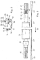
- Fig. 1 shows a schematic side view of an inventive Stranding machine 1.
- the stranding machine 1 substantially corresponds in the European patent application with the file number 03 007 675.6 and the European patent application with the Reference 03 007 672.3 disclosed stranding machine, wherein in Difference to the strand machines disclosed therein a filter strand in the filter rod machine 1 shown in Fig. 1 without Wrapping strip can be produced.
- the remaining on the suction belt 13 fiber layer 15 ' is compressed after leveling in a pressing device 17.
- the Pressing device is in this embodiment as a conveyor belt formed, which includes a corresponding press roller.
- the Conveyor belt is or the press roller is substantially in the conveying direction emotional. This is in Fig. 1 counterclockwise.
- the transfer of the densified fiber layer 15 "of the suction belt conveyor 14 the format device 20 is in this embodiment a fiber fleece.
- suction air is used by a suction air connection 18 acts on the suction belt 13.
- Compressed air connection 19 provided by means of which the fiber layer 15 "is detached from the suction belt 13 and on the format tape 23 of the format device 20 is applied.
- the format device 20 comprises a format console 21, a format set 22 and, as already mentioned, the format tape 23. Die Further components of the format device 20 are described below described in more detail.
- the formed in the format device 20 Filter strand 33 is optionally in a Besprühü 34 with, for example Polypropylene sprayed to a coat or an outer skin to provide on the filter strand 33. Subsequently, the Filter strand 33 of a cutting device 35 supplied in the filter rods 36 are cut off from the filter strand 33.
- Fig. 2 shows a schematic side view of the invention Strand machine or a part of the invention Stranding machine in direction A of Fig. 1.
- Fig. 2 is the separation the fibers 10 and the supply of the separated fibers 10 to Saugstrangier 14 shown schematically.
- the isolation corresponds to that, as for example in the European Patent applications with the file number 03 007 675.6 and 03 007 672.3. It can be any kind of in both European Patent applications mentioned singling use Find.
- a storage shaft 24 fibers are introduced.
- Two feed rollers 25 promote the fibers in the effective range of a transport roller 27, which deflects the fibers from the stowage bay.
- the separating device 26 are also separating rollers 28 are provided, which are in operative connection with a grid 29. through the transport air, which is not shown schematically in Fig. 2 (This will be to the above-mentioned European patent applications ), And the separating rollers 28 become fibers that have been essentially completely separated promoted by the grid 29, so that in the area of the fluidized bed 12 predominantly scattered fiber prevail.
- the isolated fibers also by means of transport air in particular by substantially continuous acceleration isolated the suction belt 13 of the suction belt conveyor 14th fed. Excess transport air is in the exhaust 30 or in a rolling room, not shown, of the fluidized bed 12th dissipated.
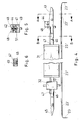
- FIG. 3 shows a top view of a format device according to the invention, the component of the strand machine 1 according to the invention is.
- the format set 22 comprises an inlet chamber 41, a sub-format 46 and an upper format 47, see also the 4 is a microwave unit 31, a cooling unit 32 and an outlet chamber 45 is provided.
- the format tape 23 is counterclockwise in the conveying direction 50 'moves. Before the inlet chamber 41 and after the outlet chamber 45, the format tape 23 is being guided. In the inlet chamber 41, the format tape 23 'laterally increasingly upward shaped round. At the end of the inlet chamber 41, the upwards curved sides of the format strip 23 'by a pair of swash plates 42 and increasingly bent inwards. To Leaving the effective range of the swash plate pair 42 is the Format band 23 'already almost completely round shaped. Between the sub-format 46 and the upper format 47 is the full Circular forming of the 23 "format tape The side edges of the format tape 23 "either face or overlap on impact.
- the format tape 23 is as wide as the size of the too generating filter strand.
- Fig. 5 is a schematic sectional view taken along the Section A-A of Fig. 4 shown. In particular, they are the swash plates 42 clearly recognizable, in the lower part of the strand cross-section 49 at least partially generate by the respective chamfer 51.
- 6 is a schematic cross-sectional view along of the section B-B of Fig. 4. At this point is the filter strand already fully formed. The filter strand or fibers in However, the filter strand do not have a completely solid Composite formed.
- the fiber layer 15 " is in the region of the inlet chamber 41 of Saugstrang detergenter 14 passed to the format tape 23 '.
- the 23" format tape holds and leads the fiber strand 33 through the microwave unit 31.
- Binding fibers are in particular bicomponent fibers in question, which include a core and a jacket, wherein the sheath comprises a lower melting material than the sheath Core.
- the European patent application with the application number 03 004 594.2 of the Applicant.
- Suitable filler fibers are, for example, cellulose fibers. These fibers are also in the aforementioned European patent application disclosed accordingly.
- the advantage of using a microwave unit 31 is the low heating of the Filter strand 33, allowing a format cooling, a contact cooling is sufficient.
- the fiber strand 33 After the microwave unit 31, according to the principle of contact cooling can be configured, the fiber strand 33 by a Cooling unit 32 out.
- cooling water is through the upper format 47 and sub-format 46 passed. There they cool and harden fused areas.
- the fiber strand 33 is then cured.
- the type, material and condition of the format tape 23 are chosen so that a fusion of binding fibers with the Format tape is not possible.
- the format tape permeable to air.
- the format tape 23 "in 23 'and then 23 remains the cured fiber strand 33 in round Shape. It can also be a fiber strand 33 in oval or elliptical Form to be formed. This is the format device or form fitting 22 corresponding oval or elliptical form.
- the format strip 23 ' is the fiber strand up and to the side free and promotes him to the cutting device 35th There is the cured Fiber strand 33 cut into filter rods 36. Before the Cutting the filter rods 36 may around the fiber strand 33 in a Spray unit 34, which may also be a dip, is a wrapping material be applied, such as a hot melt adhesive.
- the chamfer 51 of the swash plates is according to the desired Form configured of the filter strand to be formed.
Landscapes
- Cigarettes, Filters, And Manufacturing Of Filters (AREA)
- Filtering Materials (AREA)
Abstract
Description
- Fig. 1
- eine schematische Seitenansicht einer erfindungsgemäßen Strangmaschine,
- Fig. 2
- eine schematische Schnittdarstellung der Strangmaschine aus Fig. 1 in Richtung A der Fig. 1,
- Fig. 3
- im oberen Bereich eine schematische Draufsicht auf eine erfindungsgemäße Formatvorrichtung und im unteren Bereich zur besseren Veranschaulichung eine Draufsicht auf ein Formatband, das durch die Formatvorrichtung hindurch bewegbar ist,
- Fig. 4
- im oberen Bereich eine schematische Seitenansicht der Formatvorrichtung aus Fig. 3 und im unteren Bereich eine schematische Seitenansicht des Formatbandes aus Fig. 3,
- Fig. 5
- eine schematische Schnittdarstellung entlang des Schnitts A-A aus Fig. 4, und
- Fig. 6
- eine schematische Schnittdarstellung entlang B-B aus Fig. 4.
- 1
- Strangmaschine
- 10
- Fasern
- 12
- Fließbett
- 13
- Saugband
- 14
- Saugstrangförderer
- 15
- Faserschicht
- 15'
- getrimmte Faserschicht
- 15"
- verdichtete Faserschicht
- 15'''
- abgeführte Faserschicht
- 16
- Trimmer
- 17
- Pressvorrichtung
- 18
- Saugluftanschluss
- 19
- Druckluftanschluss
- 20
- Formatvorrichtung
- 21
- Formatkonsole
- 22
- Formatgarnitur
- 23, 23', 23"
- Formatband
- 24
- Stauschacht
- 25
- Einzugswalze
- 26
- Vereinzelungsvorrichtung
- 27
- Transportwalze
- 28
- Vereinzelungswalze
- 29
- Gitter
- 30
- Absaugstutzen
- 31
- Mikrowelleneinheit
- 32
- Kühleinheit
- 33
- Filterstrang
- 34
- Besprüheinheit
- 35
- Schneidvorrichtung
- 36
- Faserfilterstab
- 40
- Naht
- 41
- Einlaufkammer
- 42
- Taumelscheibe
- 43
- Auslenkrolle
- 44
- Welle
- 45
- Auslaufkammer
- 46
- Unterformat
- 47
- Oberformat
- 48
- Seitenwand
- 49
- Strangquerschnitt
- 50
- Förderrichtung
- 50'
- Förderrichtung
- 51
- Fase
Claims (27)
- Verfahren zur Herstellung eines umhüllungsmaterialstreifenfreien Filterstrangs (33) der tabakverarbeitenden Industrie, wobei Filtermaterial (10) auf ein Formatband (23) aufgebracht wird und in einer Formatvorrichtung (20) zu dem Filterstrang (33) geformt wird, wobei der Filterstrang (33) in der Formatvorrichtung (20) mit Energie beaufschlagt wird, um einen Verbund des Filtermaterials (10) zu erreichen, dadurch gekennzeichnet, dass das Filtermaterial (10) stromaufwärts des Schritts des Aufbringens auf das Formatband (23) im wesentlichen vollständig vereinzelt wird.
- Verfahren nach Anspruch 1, dadurch gekennzeichnet, dass nach der Vereinzelung des Filtermaterials (10) zunächst ein Vlies (15, 15', 15") umfassend das Filtermaterial gebildet wird, das anschließend auf dem Formatband (23) abgelegt wird.
- Verfahren nach Anspruch 2, dadurch gekennzeichnet, dass das Vlies (15, 15', 15") in einem Saugstrangförderer (14) gebildet wird.
- Verfahren nach einem oder mehreren der Ansprüche 1 bis 3, dadurch gekennzeichnet, dass das auf dem Formatband (23) aufgebrachte Filtermaterial (10) mittels wenigstens einer gefasten Scheibe (42) vorgeformt wird.
- Verfahren nach Anspruch 4, dadurch gekennzeichnet, dass zwei Scheiben (42) Verwendung finden, deren Fasen (51) insbesondere aneinander angrenzen.
- Verfahren nach Anspruch 5, dadurch gekennzeichnet, dass die Scheiben (42) Taumelscheiben sind.
- Verfahren nach einem oder mehreren der Ansprüche 1 bis 6, dadurch gekennzeichnet, dass die Energie Mikrowellenenergie oder Heißluft ist.
- Verfahren nach einem oder mehreren der Ansprüche 1 bis 7, dadurch gekennzeichnet, dass nach Beaufschlagung mit Energie der Filterstrang (33) gekühlt wird.
- Verfahren nach einem oder mehreren der Ansprüche 1 bis 8, dadurch gekennzeichnet, dass der Filterstrang (33) mit einem aushärtbaren Mantel aus einem flüssigen Material versehen wird.
- Verfahren zur Herstellung eines Filterelements (36) der tabakverarbeitenden Industrie umfassend ein Verfahren nach einem oder mehreren der Ansprüche 1 bis 9, wobei anschließend der Filterstrang (33) in Filterelemente (36) abgelängt wird.
- Vorrichtung zur Herstellung eines umhüllungsmaterialstreifenfreien Filterstrangs (33) der tabakverarbeitenden Industrie umfassend eine Formatvorrichtung (20), in der ein Formatband (23) bewegbar ist, das um Filtermaterial (10) endlicher Länge wickelbar ist, dadurch gekennzeichnet, dass eine Aufschauervorrichtung (12, 13, 14, 26) stromaufwärts der Formatvorrichtung (20) vorgesehen ist, mittels der im wesentlichen vollständig vereinzelte Fasern (10) zu einem Vlies (15, 15', 15") aufschauerbar sind.
- Vorrichtung nach Anspruch 11, dadurch gekennzeichnet, dass die Aufschauervorrichtung (12-14, 26) einen Saugstrangförderer (14) umfasst.
- Vorrichtung nach Anspruch 11 oder 12, dadurch gekennzeichnet, dass im Bereich der Formatvorrichtung (20) wenigstens eine gefaste Scheibe (42) vorgesehen ist.
- Vorrichtung nach Anspruch 13, dadurch gekennzeichnet, dass zwei gefaste Scheiben (42) vorgesehen sind.
- Vorrichtung nach Anspruch 13 oder 14, dadurch gekennzeichnet, dass wenigstens eine Scheibe (42) eine Taumelscheibe ist.
- Vorrichtung nach einem oder mehreren der Ansprüche 11 bis 15, dadurch gekennzeichnet, dass eine dem Filtermaterial (10) Energie zuführende Einheit (31) vorgesehen ist.
- Vorrichtung nach Anspruch 16, dadurch gekennzeichnet, dass die Energie in Form von Mikrowellen oder Heißluft zuführbar ist.
- Vorrichtung nach einem oder mehreren der Ansprüche 11 bis 17, dadurch gekennzeichnet, dass eine Ummantelungsvorrichtung (34) vorgesehen ist, mittels der der Filterstrang (33) mit einer Außenhaut versehbar ist.
- Vorrichtung nach einem oder mehreren der Ansprüche 11 bis 18, dadurch gekennzeichnet, dass die Breite des Formatbandes (23) wenigstens gleich dem Umfang des zu bildenden Filterstrangs (33) ist.
- Formatvorrichtung (20) der tabakverarbeitenden Industrie, umfassend ein Unterformat (46) und ein Oberformat (47), wobei die Formatvorrichtung (20) einen Einlaufbereich (41) aufweist und wobei die Formatvorrichtung (20) ausgestaltet ist, um ein Formatband (23), das durch die Formatvorrichtung (20) bewegbar ist, um Material (10), insbesondere Filtermaterial (10), der tabakverarbeitenden Industrie, zu wickeln, dadurch gekennzeichnet, dass im Einlaufbereich (41) ein drehbar gelagertes Scheibenpaar (42) vorgesehen ist, das ausgebildet ist, um wenigstens einen Teil des Formatbandes (23) fortschreitend umzubiegen.
- Formatvorrichtung nach Anspruch (20), dadurch gekennzeichnet, dass das Scheibenpaar (42) ein Taumelscheibenpaar ist.
- Formatvorrichtung nach Anspruch 20 oder 21, dadurch gekennzeichnet, dass die Drehachsen (44) der Scheiben (42) koaxial sind.
- Formatvorrichtung nach Anspruch 20 oder 21, dadurch gekennzeichnet, dass für die Scheiben (42) eine gemeinsame Drehachse (44) vorgesehen ist.
- Formatvorrichtung nach einem oder mehreren der Ansprüche 20 bis 23, dadurch gekennzeichnet, dass die Scheiben (42) an deren jeweiligen Umfangsfläche gefast sind.
- Formatvorrichtung nach Anspruch 24, dadurch gekennzeichnet, dass wenigstens ein Teil der Fase (51) einen Teilkreis, insbesondere einen Viertelkreis, umfasst.
- Verwendung eines Taumelscheibenpaars (42) im Bereich einer Formatvorrichtung (20) der tabakverarbeitenden Industrie zur Verbiegung eines Formatbandes (23).
- Verwendung nach Anspruch 26, dadurch gekennzeichnet, dass die Verbiegung quer zur Förderrichtung (50) des Formatbandes (23) geschieht.
Applications Claiming Priority (2)
| Application Number | Priority Date | Filing Date | Title |
|---|---|---|---|
| DE10354797 | 2003-11-21 | ||
| DE10354797A DE10354797A1 (de) | 2003-11-21 | 2003-11-21 | Verfahren und Vorrichtung zur Herstellung eines umhüllungsmaterialstreifenfreien Filterstrangs der tabakverarbeitenden Industrie |
Publications (2)
| Publication Number | Publication Date |
|---|---|
| EP1532881A2 true EP1532881A2 (de) | 2005-05-25 |
| EP1532881A3 EP1532881A3 (de) | 2005-06-01 |
Family
ID=34428877
Family Applications (1)
| Application Number | Title | Priority Date | Filing Date |
|---|---|---|---|
| EP04024223A Withdrawn EP1532881A3 (de) | 2003-11-21 | 2004-10-12 | Verfahren und Vorrichtung zur Herstellung eines umhüllungsmaterialstreifenfreien Filterstrangs der tabakverarbeitenden Industrie |
Country Status (5)
| Country | Link |
|---|---|
| US (1) | US20050113232A1 (de) |
| EP (1) | EP1532881A3 (de) |
| JP (1) | JP2005151993A (de) |
| CN (1) | CN1640334A (de) |
| DE (1) | DE10354797A1 (de) |
Cited By (1)
| Publication number | Priority date | Publication date | Assignee | Title |
|---|---|---|---|---|
| IT201600090857A1 (it) * | 2016-09-08 | 2018-03-08 | Montrade S P A | Procedimento ed apparecchiatura per la produzione di una bacchetta filtro per articoli da fumo |
Families Citing this family (6)
| Publication number | Priority date | Publication date | Assignee | Title |
|---|---|---|---|---|
| DE102010000677A1 (de) * | 2010-01-05 | 2011-07-07 | Hauni Maschinenbau AG, 21033 | Vorrichtung zur gleichzeitigen Herstellung von wenigstens zwei Faservliesen für die Herstellung von Filterstäben der Tabak verarbeitenden Industrie |
| DE102011015047A1 (de) * | 2011-03-24 | 2012-09-27 | Hauni Maschinenbau Ag | Heißleimschmelzvorrichtung |
| DE102011015045A1 (de) * | 2011-03-24 | 2012-09-27 | Hauni Maschinenbau Ag | Einrichtung zum Aufschmelzen von Heißleim für Produkte der Tabak verarbeitenden Industrie |
| TW201328860A (zh) * | 2012-01-13 | 2013-07-16 | Fuoshan Hao Bo Environment Prot Product Co Ltd | 紙漿模塑一體化翻轉自動成型機械及技術 |
| DE102013222055A1 (de) | 2013-10-30 | 2015-04-30 | Hauni Maschinenbau Ag | Einrichtung und Verfahren zur Herstellung eines umhüllungsmaterialfreien Filterstrangs sowie Formateinheit und Führungsdorn zur Verwendung in dieser Einrichtung |
| WO2017086419A1 (ja) * | 2015-11-18 | 2017-05-26 | 中外製薬株式会社 | 液性免疫応答の増強方法 |
Family Cites Families (22)
| Publication number | Priority date | Publication date | Assignee | Title |
|---|---|---|---|---|
| CH308903A (de) * | 1952-09-09 | 1955-08-15 | Mueller Paul A | Verfahren und Maschine zur Herstellung eines Filterstranges aus einem wässrigen Faserbrei. |
| NL128335C (de) * | 1956-12-18 | |||
| US3470008A (en) * | 1965-09-27 | 1969-09-30 | Celanese Corp | Process for making paperless cigarette filter |
| US3377220A (en) * | 1967-06-09 | 1968-04-09 | American Filtrona Corp | Process for making stable elongated elements |
| US3560298A (en) * | 1968-07-30 | 1971-02-02 | Reynolds Tobacco Co R | Paperless cigarette filter and apparatus for manufacture thereof |
| US3819435A (en) * | 1968-11-13 | 1974-06-25 | Celanese Corp | Process for making cigarette filters from short synthetic fibers |
| GB1387404A (en) * | 1971-04-15 | 1975-03-19 | Molins Ltd | Continuous filter rod making machines |
| US3852009A (en) * | 1972-02-07 | 1974-12-03 | Celanese Corp | Filter making apparatus |
| AU531418B2 (en) * | 1978-09-11 | 1983-08-25 | Philip Morris Products Inc. | Cigarette filters |
| US4357188A (en) * | 1979-10-22 | 1982-11-02 | Mitsubishi Rayon Co., Ltd. | Method for manufacturing cigarette filters |
| US4507107A (en) * | 1979-11-21 | 1985-03-26 | American Filtrona Corporation | Filter manufacturing technique |
| US4508525A (en) * | 1980-05-27 | 1985-04-02 | American Filtrona Corporation | Method and apparatus for producing tobacco smoke filter having improved tar/carbon monoxide ratio |
| GB2145918B (en) * | 1980-08-04 | 1985-10-16 | Molins Plc | Producing filler material particularly for cigarette filters |
| US4528050A (en) * | 1981-07-30 | 1985-07-09 | Molins Plc | Producing filler material, particularly for cigarette filters |
| JPS6048156B2 (ja) * | 1982-07-07 | 1985-10-25 | 三菱アセテート株式会社 | タバコスモ−クフイルタ− |
| US4780988A (en) * | 1983-05-25 | 1988-11-01 | Korber Ag | Method of producing rod-shaped incipient plant carrying devices |
| US4567902A (en) * | 1983-08-11 | 1986-02-04 | Philip Morris Incorporated | Tobacco trimmer device |
| JPH0231593Y2 (de) * | 1984-09-27 | 1990-08-27 | ||
| US5732718A (en) * | 1994-08-23 | 1998-03-31 | Schweitzer-Mauduit International, Inc. | Selective filtration device |
| US5736473A (en) * | 1994-09-14 | 1998-04-07 | Kimberly-Clark Corp. | Fibrous composite structure including particulates |
| DE10217410A1 (de) * | 2002-04-18 | 2003-10-30 | Hauni Maschinenbau Ag | Zigarettenfilter und Verfahren zur Herstellung desselben |
| EP1464239B1 (de) * | 2003-04-03 | 2006-11-22 | Hauni Maschinenbau AG | Verfahren und Einrichtung zur Herstellung eines Filterstranges |
-
2003
- 2003-11-21 DE DE10354797A patent/DE10354797A1/de not_active Ceased
-
2004
- 2004-10-12 EP EP04024223A patent/EP1532881A3/de not_active Withdrawn
- 2004-11-15 US US10/986,832 patent/US20050113232A1/en not_active Abandoned
- 2004-11-19 JP JP2004335783A patent/JP2005151993A/ja not_active Withdrawn
- 2004-11-22 CN CN200410103358.3A patent/CN1640334A/zh active Pending
Cited By (2)
| Publication number | Priority date | Publication date | Assignee | Title |
|---|---|---|---|---|
| IT201600090857A1 (it) * | 2016-09-08 | 2018-03-08 | Montrade S P A | Procedimento ed apparecchiatura per la produzione di una bacchetta filtro per articoli da fumo |
| WO2018047075A1 (en) * | 2016-09-08 | 2018-03-15 | Montrade S.P.A. | A method and apparatus for producing a filter rod for smoking articles |
Also Published As
| Publication number | Publication date |
|---|---|
| CN1640334A (zh) | 2005-07-20 |
| JP2005151993A (ja) | 2005-06-16 |
| DE10354797A1 (de) | 2005-06-30 |
| EP1532881A3 (de) | 2005-06-01 |
| US20050113232A1 (en) | 2005-05-26 |
Similar Documents
| Publication | Publication Date | Title |
|---|---|---|
| DE69425051T3 (de) | Verfahren zur herstellung einer isolierenden mineralfaserbahn | |
| DE19751598A1 (de) | Verfahren und Vorrichtung zum Behandeln eines Filtertowstreifens | |
| WO2016162273A1 (de) | Vorrichtung und verfahren zum herstellen einer mehrlagigen dreidimensionalen strukturfolie, mehrlagige strukturfolie und stabförmiger artikel aus einer solchen strukturfolie | |
| EP1464239B1 (de) | Verfahren und Einrichtung zur Herstellung eines Filterstranges | |
| EP1532881A2 (de) | Verfahren und Vorrichtung zur Herstellung eines umhüllungsmaterialstreifenfreien Filterstrangs der tabakverarbeitenden Industrie | |
| EP1275311B1 (de) | Vorrichtung zur Vorbereitung eines Faserstranges der tabakverarbeitenden Industrie | |
| DE102020107421A1 (de) | Vorrichtung und Verfahren zum Herstellen eines Strangs der Tabak verarbeitenden Industrie | |
| DE102019116263A1 (de) | Einrichtung mit einer Mehrfach-Strangbildungsvorrichtung und Verfahren der Tabak verarbeitenden Industrie | |
| EP1625799A1 (de) | Anordnung zur Herstellung wenigstens eines Filterstrangs | |
| EP1464240B1 (de) | Verfahren und Vorrichtung zur Herstellung eines Vlieses für die Herstellung von Filterstäben | |
| DE1947894A1 (de) | Vorrichtung zum Herstellen eines Vlieses aus regellos gelagerten Fasern | |
| DE102006045810B4 (de) | Saugstrangförderer und Verfahren zur Herstellung eines Strangs der Tabak verarbeitenden Industrie | |
| EP1532876B1 (de) | Kühlung für eine Wand zum Führen eines Strangs der tabakverarbeitenden Industrie | |
| EP1616985A1 (de) | Herstellung einer Mineralfaserbahn mit weitgehend aufrecht stehenden Mineralfasern | |
| DE2437331A1 (de) | Einrichtung zum herstellen von faserverstaerktem formmaterial | |
| DE60038566T2 (de) | Glasfaserbahnrolle und Herstellungsverfahren von Rolle und Glasfaserbahn | |
| DE102023122163A1 (de) | Crimpwalze, Crimpwalzenpaar, Crimpvorrichtung und Maschine der Tabak verarbeitenden Industrie sowie Verfahren zum Crimpen einer Flachbahn und Herstellen eines Strangs, stabförmige Artikel | |
| DE19854662A1 (de) | Tabakschneidverfahren und -vorrichtung | |
| DE2141872B2 (de) | ZigarettenhersteUungsmaschine | |
| DE69322614T2 (de) | Verfahren und Vorrichtung zur Herstellung von Zigaretten | |
| EP1405573A2 (de) | Egalisator für eine Zigarettenstrangmaschine | |
| EP1504681B2 (de) | Verfahren und Vorrichtung zur Herstellung eines Filterstrangs | |
| DE69706937T2 (de) | Zuführungsvorrichtung für geschnittenen Tabak zum Formen eines Stranges in einer Zigarettenherstellungsmaschine | |
| DE60304367T2 (de) | Verfahren und vorrichtung zur stabilisierung von rändern eines vliesstoffes | |
| DE3508497A1 (de) | Verfahren und vorrichtung zum bilden von tabakportionen, insbesondere fuer die herstellung eines aus aufeinanderfolgenden tabakabschnitten unterschiedlicher arten gebildeten tabakstranges |
Legal Events
| Date | Code | Title | Description |
|---|---|---|---|
| PUAI | Public reference made under article 153(3) epc to a published international application that has entered the european phase |
Free format text: ORIGINAL CODE: 0009012 |
|
| PUAL | Search report despatched |
Free format text: ORIGINAL CODE: 0009013 |
|
| AK | Designated contracting states |
Kind code of ref document: A2 Designated state(s): AT BE BG CH CY CZ DE DK EE ES FI FR GB GR HU IE IT LI LU MC NL PL PT RO SE SI SK TR |
|
| AX | Request for extension of the european patent |
Extension state: AL HR LT LV MK |
|
| AK | Designated contracting states |
Kind code of ref document: A3 Designated state(s): AT BE BG CH CY CZ DE DK EE ES FI FR GB GR HU IE IT LI LU MC NL PL PT RO SE SI SK TR |
|
| AX | Request for extension of the european patent |
Extension state: AL HR LT LV MK |
|
| 17P | Request for examination filed |
Effective date: 20051029 |
|
| AKX | Designation fees paid |
Designated state(s): AT BE BG CH CY CZ DE DK EE ES FI FR GB GR HU IE IT LI LU MC NL PL PT RO SE SI SK TR |
|
| 17Q | First examination report despatched |
Effective date: 20060222 |
|
| GRAP | Despatch of communication of intention to grant a patent |
Free format text: ORIGINAL CODE: EPIDOSNIGR1 |
|
| STAA | Information on the status of an ep patent application or granted ep patent |
Free format text: STATUS: THE APPLICATION IS DEEMED TO BE WITHDRAWN |
|
| 18D | Application deemed to be withdrawn |
Effective date: 20071009 |