EP1533096A1 - A manufacturing process for water-cleaning guns. - Google Patents
A manufacturing process for water-cleaning guns. Download PDFInfo
- Publication number
- EP1533096A1 EP1533096A1 EP04024890A EP04024890A EP1533096A1 EP 1533096 A1 EP1533096 A1 EP 1533096A1 EP 04024890 A EP04024890 A EP 04024890A EP 04024890 A EP04024890 A EP 04024890A EP 1533096 A1 EP1533096 A1 EP 1533096A1
- Authority
- EP
- European Patent Office
- Prior art keywords
- mould
- cores
- exhibits
- injection
- internal
- Prior art date
- Legal status (The legal status is an assumption and is not a legal conclusion. Google has not performed a legal analysis and makes no representation as to the accuracy of the status listed.)
- Withdrawn
Links
- 238000004519 manufacturing process Methods 0.000 title claims abstract description 19
- 238000004140 cleaning Methods 0.000 title claims description 6
- 239000007788 liquid Substances 0.000 claims abstract description 20
- 238000000034 method Methods 0.000 claims abstract description 17
- 239000000463 material Substances 0.000 claims abstract description 16
- 230000008569 process Effects 0.000 claims abstract description 16
- 239000004033 plastic Substances 0.000 claims abstract description 14
- 229920003023 plastic Polymers 0.000 claims abstract description 14
- 238000000605 extraction Methods 0.000 claims abstract description 13
- 238000002347 injection Methods 0.000 claims description 38
- 239000007924 injection Substances 0.000 claims description 38
- 238000000465 moulding Methods 0.000 claims description 7
- XLYOFNOQVPJJNP-UHFFFAOYSA-N water Substances O XLYOFNOQVPJJNP-UHFFFAOYSA-N 0.000 claims description 7
- 238000003780 insertion Methods 0.000 claims description 3
- 230000037431 insertion Effects 0.000 claims description 3
- 239000012815 thermoplastic material Substances 0.000 claims description 2
- 230000007246 mechanism Effects 0.000 description 8
- 208000015943 Coeliac disease Diseases 0.000 description 7
- 230000008901 benefit Effects 0.000 description 3
- 230000015572 biosynthetic process Effects 0.000 description 2
- 230000008878 coupling Effects 0.000 description 2
- 238000010168 coupling process Methods 0.000 description 2
- 238000005859 coupling reaction Methods 0.000 description 2
- 239000012530 fluid Substances 0.000 description 2
- 238000007711 solidification Methods 0.000 description 2
- 230000008023 solidification Effects 0.000 description 2
- 239000004952 Polyamide Substances 0.000 description 1
- 230000009471 action Effects 0.000 description 1
- 230000004888 barrier function Effects 0.000 description 1
- 238000006243 chemical reaction Methods 0.000 description 1
- 238000005520 cutting process Methods 0.000 description 1
- 239000003599 detergent Substances 0.000 description 1
- 238000004880 explosion Methods 0.000 description 1
- 239000003365 glass fiber Substances 0.000 description 1
- 239000000203 mixture Substances 0.000 description 1
- 210000000056 organ Anatomy 0.000 description 1
- 229920002647 polyamide Polymers 0.000 description 1
- 230000000630 rising effect Effects 0.000 description 1
- 238000000926 separation method Methods 0.000 description 1
- 229920001169 thermoplastic Polymers 0.000 description 1
- 239000004416 thermosoftening plastic Substances 0.000 description 1
- 239000002699 waste material Substances 0.000 description 1
Images


Classifications
-
- B—PERFORMING OPERATIONS; TRANSPORTING
- B29—WORKING OF PLASTICS; WORKING OF SUBSTANCES IN A PLASTIC STATE IN GENERAL
- B29C—SHAPING OR JOINING OF PLASTICS; SHAPING OF MATERIAL IN A PLASTIC STATE, NOT OTHERWISE PROVIDED FOR; AFTER-TREATMENT OF THE SHAPED PRODUCTS, e.g. REPAIRING
- B29C45/00—Injection moulding, i.e. forcing the required volume of moulding material through a nozzle into a closed mould; Apparatus therefor
- B29C45/17—Component parts, details or accessories; Auxiliary operations
- B29C45/26—Moulds
- B29C45/261—Moulds having tubular mould cavities
-
- B—PERFORMING OPERATIONS; TRANSPORTING
- B29—WORKING OF PLASTICS; WORKING OF SUBSTANCES IN A PLASTIC STATE IN GENERAL
- B29C—SHAPING OR JOINING OF PLASTICS; SHAPING OF MATERIAL IN A PLASTIC STATE, NOT OTHERWISE PROVIDED FOR; AFTER-TREATMENT OF THE SHAPED PRODUCTS, e.g. REPAIRING
- B29C45/00—Injection moulding, i.e. forcing the required volume of moulding material through a nozzle into a closed mould; Apparatus therefor
- B29C45/17—Component parts, details or accessories; Auxiliary operations
- B29C45/26—Moulds
- B29C2045/2683—Plurality of independent mould cavities in a single mould
-
- B—PERFORMING OPERATIONS; TRANSPORTING
- B29—WORKING OF PLASTICS; WORKING OF SUBSTANCES IN A PLASTIC STATE IN GENERAL
- B29C—SHAPING OR JOINING OF PLASTICS; SHAPING OF MATERIAL IN A PLASTIC STATE, NOT OTHERWISE PROVIDED FOR; AFTER-TREATMENT OF THE SHAPED PRODUCTS, e.g. REPAIRING
- B29C45/00—Injection moulding, i.e. forcing the required volume of moulding material through a nozzle into a closed mould; Apparatus therefor
- B29C45/17—Component parts, details or accessories; Auxiliary operations
- B29C45/26—Moulds
- B29C45/27—Sprue channels ; Runner channels or runner nozzles
- B29C45/2701—Details not specific to hot or cold runner channels
- B29C45/2708—Gates
Definitions
- the production process relates to a moulding process of a liquid conduit internal of a water gun, comprising an interception device of the fluid.
- Water-cleaning guns are known in the prior art, and are connected to water-cleaning machines, and often include various forms of internal conduits for transport of a liquid, which conduits are shaped according to the performance type required of the guns, and the market sectors the guns are aimed at.
- the guns which work at high pressure regimes, have to be able to support the pressures they work at, preventing any possibility of internal explosion and thus ensuring a reliable working life. They also obviously have to guarantee a good seal of the liquid running through them.
- the internal liquid transport conduit is generally made of an assembly of metallic conduits.
- the assembly is composed of a first tract of conduit which is connected to the detergent liquid aspiration pipe, and internally contains a ball mechanism for opening and closing the liquid supply at the moment when the operator presses the gun trigger to activate the mechanism.
- a second tract of conduit is connected to the first tract, for expulsion of the pressurised liquid.
- connection of the two tracts is realised preferably by a thread, which requires a rather laborious assembly stage.
- an obturator mechanism is interpositioned, which has the function of the ball mechanism as described above.
- This mechanism has many functional limitations, among which seal problems due to the presence of many organs and the possibility of excessive play appearing between them.
- the main aim of the present invention is to provide a process for production of the internal liquid transport conduit, with which a good compromise between production costs, assembly costs and technical, functional and duration performance can be reached.
- 1 denotes in its entirety a mould installed on a press of known type and not illustrated.
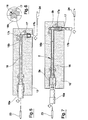
- the mould 1 exhibits a plurality of injection chambers 12, preferably four, each of which is for moulding a liquid transport conduit 2 constituting the internal part of the water gun.
- the mould 1 is subdivided into a mobile part 4, comprising a top die 5, and a fixed part, comprising a bottom die 7 and a rest base 8.
- the rest base 8 internally exhibits a cavity 9 for containing the bottom die 7.
- the top die 5 and the bottom die 7 exhibit a plurality of coaxial through-holes 10, preferably parallel.
- the plurality of holes 10 is coupled to a respective plurality of rods 11 in order to enable the top die 5 to translate with respect to the bottom die 7, from a detached position to a position of contact.
- the top die 5 exhibits a lower surface 5a which, in the contact position, is near to an upper surface 7a of the bottom die 7, in order to generate a common forming plane 21 of the moulded internal liquid transport conduits 2.
- the top and bottom dies afford the injection chambers 12 for moulding the internal conduits 2 for transporting liquid.
- Each injection chamber 12 communicates with a common injection channel 13 which is a vehicle for pressure-injection of a molten plastic material.
- a sprue 22 also solidifies within the injection channel 13.
- the injection channel 13 exhibits a first tract 14 which crosses the top die 5.
- the first tract 14 exhibits, on the top of the top die 5, an inlet 14a which proceeds internally thereof with a plurality of branches 14b, one for each injection chamber 12, each terminating on the lower surface 5a of the top die 5 at the position of the forming plane 21.
- the injection channel 13 proceeds with a plurality of second tracts 15 which from the upper surface 7a of the bottom die 7 proceed below the forming plane 21 up until they reach the injection chamber.
- the second tracts 15 each exhibit a first end 15a which connects to a respective branch 14b, and a second end 15b which connects up to the injection chamber 12.
- This conformation of the injection channel 13, and especially the plurality of second tracts 15, is made in this way in order to actuate a special injection technique known as submarine gate injection.
- Each second tract 15 develops below the forming plane 21 in order to allow, during extraction of the internal conduits 2, an automatic breaking of the connection which forms between the sprue 22 and the moulded internal conduit 2.
- the injection channel 13 is constituted by a plurality of nozzles which inject a molten thermoplastic material directly into an injection chamber 12.
- This conformation of the injection channel 13 is developed in order to obtain the process known as canal injection, preventing the formation of sprues and thus reducing to a minimum all waste materials.
- the internal liquid transport conduit 2 which exhibits a first tract of conduit 3a connected to the aspiration tube and a second tract of conduit 3b for expelling the liquid, which first and second tracts of conduit are interconnected and arranged in an L shape, requires two cylindrical cores in order to form a single channel for passage of the fluid.
- a pair of cores 16, 17, are inserted into each injection chamber 12; the cores are respectively a long core 16 and a short core 17, and are illustrated in figures 5 and 7.
- the short core 17 is friction-housed at ends thereof 17a, 17b, in respective chambers directed afforded in the injection chamber 12, while the long core 16 has a first end 16a which is friction-housed in a chamber afforded in the injection chamber 12, and a second end 16b, opposite the first end 16a, which has a plug-type end 18, illustrated in figure 6, which couples with the cylindrical part of the short core 17.
- the coupling enables, during the moulding process, obtaining of a single passage channel, avoiding formation, at the intersection between the first tract of conduit 3a and the second tract of conduit 3b, of a film of plastic material which would have to be removed at the end of the moulding process.
- An extraction plate 19 is coupled to the plurality of rods 11; the plate 19 is interpositioned between the rest base 8 and the bottom die 7, internally of the cavity 9, and can be translated from a rest position in contact with the bottom of the cavity 9 of the rest base 8 to a work position, in contact with the bottom die 7.
- a plurality of extractors 20 is connected to the extraction plate 19, on the surface thereof which faces the bottom die 7. Each of the plurality of extractors 20 terminates in the injection chamber 12 and is for extracting the internal conduits 2 from the mould.
- the plurality of extractors 20 comprises a central extractor 20a which terminates in the injection channel 13 and aids detachment of the sprue 22, which solidifies internally of the channel, from the internal liquid transport conduit 2.
- the first stage illustrated in figure 5, relates to the automatic positioning, using hydraulic pistons 23, 24, of the cores 16, 17 internally of the injection chamber.
- the positioning is done while the mould is open, as in figure 1, i.e. when the top die 5 is in the detached position, held up by the plurality of rods 11.
- the mould 1 is closed and the plastic material injected under pressure, see figure 2;
- the plastic material can be a thermoplastic mix, for example polyamide including 30% of glass fibre.
- the cores 16, 17 are extracted, as illustrated in figure 7.
- the extraction operation is the reverse of the positioning operation, i.e. the long core 16 has to be extracted before the short core 17, so as correctly to disengage the plug 18 from the short core 17.
- the mould is opened, bringing the top die 5 into the detached position.
- the internal conduits 2 can be extracted from the injection chamber 12 by performing a translation of the extraction plate 19 and thereafter the plurality of extractors 20, along the plurality of rods 11, as illustrated in figure 3.
- the location of the second tract 15 of the injection channel 13, means that during extraction the sprue, which has solidified internally of the injection channel 13, detaches automatically from the internal liquid transport conduits 2, which have just been formed, as shown in figure 4.
- the second tract 15, below the forming plane 21 and internally of the bottom die 7, is a barrier to the free rising of the sprue, which breaks due to the cutting force generated following the forces exerted by the extractors 20 and 20a and the reaction of the second tract 15.
- An advantage of the invention is to provide a moulding process which produces an internal conduit 2 of liquid transport made in a single piece of plastic material, which at the same time reduces production costs and assembly times.
- a further advantage of the invention is to realise the internal liquid transport conduit in a plastic material which can internally contain a ball mechanism for opening and closing a liquid supply.
Landscapes
- Engineering & Computer Science (AREA)
- Manufacturing & Machinery (AREA)
- Mechanical Engineering (AREA)
- Moulds For Moulding Plastics Or The Like (AREA)
Applications Claiming Priority (2)
| Application Number | Priority Date | Filing Date | Title |
|---|---|---|---|
| IT000109A ITRE20030109A1 (it) | 2003-11-13 | 2003-11-13 | Procedimento di produzione di pistola idropulitrice. |
| ITRE20030109 | 2003-11-13 |
Publications (1)
| Publication Number | Publication Date |
|---|---|
| EP1533096A1 true EP1533096A1 (en) | 2005-05-25 |
Family
ID=34430800
Family Applications (1)
| Application Number | Title | Priority Date | Filing Date |
|---|---|---|---|
| EP04024890A Withdrawn EP1533096A1 (en) | 2003-11-13 | 2004-10-20 | A manufacturing process for water-cleaning guns. |
Country Status (3)
| Country | Link |
|---|---|
| US (1) | US20050104256A1 (it) |
| EP (1) | EP1533096A1 (it) |
| IT (1) | ITRE20030109A1 (it) |
Cited By (1)
| Publication number | Priority date | Publication date | Assignee | Title |
|---|---|---|---|---|
| WO2007011943A3 (en) * | 2005-07-19 | 2007-05-03 | Valeo Electrical Sys Inc | Nozzle and method of making the same |
Families Citing this family (2)
| Publication number | Priority date | Publication date | Assignee | Title |
|---|---|---|---|---|
| US7586056B2 (en) * | 2006-09-15 | 2009-09-08 | Shin-Etsu Polymer Co., Ltd | Resin molded body, receiving jig and method for manufacturing push button switch member |
| CN110744783A (zh) * | 2019-11-03 | 2020-02-04 | 广东联邦家私集团有限公司 | 一种家具生产用的一次成型注压模具 |
Citations (5)
| Publication number | Priority date | Publication date | Assignee | Title |
|---|---|---|---|---|
| JPS60161116A (ja) * | 1984-01-31 | 1985-08-22 | Kinjiyou Gomme Kk | ゴム製又は樹脂製の屈曲管接手の製法 |
| JPH0976296A (ja) * | 1995-09-20 | 1997-03-25 | Japan Steel Works Ltd:The | 複数品の成形用金型およびこの金型を使用した複数品の成形方法 |
| EP0773071A1 (en) * | 1995-11-07 | 1997-05-14 | ANNOVI E REVERBERI S.p.A | Lance for high-pressure wash devices |
| DE19631354A1 (de) * | 1996-08-02 | 1998-05-07 | Kaercher Gmbh & Co Alfred | Handspritzpistole |
| JP2002283418A (ja) * | 2001-03-26 | 2002-10-03 | Sekisui Chem Co Ltd | 射出成形用金型 |
-
2003
- 2003-11-13 IT IT000109A patent/ITRE20030109A1/it unknown
-
2004
- 2004-10-20 EP EP04024890A patent/EP1533096A1/en not_active Withdrawn
- 2004-11-10 US US10/984,889 patent/US20050104256A1/en not_active Abandoned
Patent Citations (5)
| Publication number | Priority date | Publication date | Assignee | Title |
|---|---|---|---|---|
| JPS60161116A (ja) * | 1984-01-31 | 1985-08-22 | Kinjiyou Gomme Kk | ゴム製又は樹脂製の屈曲管接手の製法 |
| JPH0976296A (ja) * | 1995-09-20 | 1997-03-25 | Japan Steel Works Ltd:The | 複数品の成形用金型およびこの金型を使用した複数品の成形方法 |
| EP0773071A1 (en) * | 1995-11-07 | 1997-05-14 | ANNOVI E REVERBERI S.p.A | Lance for high-pressure wash devices |
| DE19631354A1 (de) * | 1996-08-02 | 1998-05-07 | Kaercher Gmbh & Co Alfred | Handspritzpistole |
| JP2002283418A (ja) * | 2001-03-26 | 2002-10-03 | Sekisui Chem Co Ltd | 射出成形用金型 |
Non-Patent Citations (3)
| Title |
|---|
| PATENT ABSTRACTS OF JAPAN vol. 009, no. 326 (M - 441) 21 December 1985 (1985-12-21) * |
| PATENT ABSTRACTS OF JAPAN vol. 1997, no. 07 31 July 1997 (1997-07-31) * |
| PATENT ABSTRACTS OF JAPAN vol. 2003, no. 02 5 February 2003 (2003-02-05) * |
Cited By (1)
| Publication number | Priority date | Publication date | Assignee | Title |
|---|---|---|---|---|
| WO2007011943A3 (en) * | 2005-07-19 | 2007-05-03 | Valeo Electrical Sys Inc | Nozzle and method of making the same |
Also Published As
| Publication number | Publication date |
|---|---|
| ITRE20030109A1 (it) | 2005-05-14 |
| US20050104256A1 (en) | 2005-05-19 |
Similar Documents
| Publication | Publication Date | Title |
|---|---|---|
| EP2621704B1 (en) | Extraction method for extracting the air in an injection mould | |
| KR101683032B1 (ko) | 사출 금형장치의 사이드 게이트의 자동절단 및 성형물의 취출 방법 | |
| US20050104256A1 (en) | Manufacturing process for water-cleaning guns | |
| CN217121700U (zh) | 一种双斜顶一体脱模油泵座模具 | |
| CN209289668U (zh) | 一体式多端子埋入注塑模具 | |
| KR200324439Y1 (ko) | 사출금형 | |
| CN211662554U (zh) | 一种模内切环形浇口注塑模 | |
| CN110154331B (zh) | 一种基于冷却管路实现顶出的注塑模具 | |
| JPH0720640B2 (ja) | 射出成形ノズル装置 | |
| EP1252009B1 (en) | Injection moulding methods and apparatus | |
| US3209419A (en) | Method and apparatus for die casting | |
| CN114311551A (zh) | 一种模具的内切机构 | |
| CN206493530U (zh) | 一种模具侧流道自动切断结构 | |
| JP2717758B2 (ja) | 射出成形方法および射出成形用金型 | |
| CN211105217U (zh) | 一种塑胶生产成型装置 | |
| JP2002347085A (ja) | 射出成形金型 | |
| CN215242497U (zh) | 一种开模后浇注口自动断料的模具 | |
| KR20000000445A (ko) | 선단부에 다수의 게이트를 가지는 사출성형기용 주입노즐 | |
| CN222944480U (zh) | 一种水道气辅成型模具结构 | |
| CN220373775U (zh) | 一种用于模内嵌件成型的注塑模具 | |
| CN220219547U (zh) | 一种导管注塑模具 | |
| CN223657529U (zh) | 一种铜排注塑滑块 | |
| CN222495247U (zh) | 一种具有防损伤潜圆顶针结构的注塑模具 | |
| CN218966032U (zh) | 注塑模具 | |
| CN219294641U (zh) | 一种生产汽车配件用注塑模具 |
Legal Events
| Date | Code | Title | Description |
|---|---|---|---|
| PUAI | Public reference made under article 153(3) epc to a published international application that has entered the european phase |
Free format text: ORIGINAL CODE: 0009012 |
|
| AK | Designated contracting states |
Kind code of ref document: A1 Designated state(s): AT BE BG CH CY CZ DE DK EE ES FI FR GB GR HU IE IT LI LU MC NL PL PT RO SE SI SK TR |
|
| AX | Request for extension of the european patent |
Extension state: AL HR LT LV MK |
|
| 17P | Request for examination filed |
Effective date: 20050919 |
|
| AKX | Designation fees paid |
Designated state(s): AT BE BG CH CY CZ DE DK EE ES FI FR GB GR HU IE IT LI LU MC NL PL PT RO SE SI SK TR |
|
| GRAP | Despatch of communication of intention to grant a patent |
Free format text: ORIGINAL CODE: EPIDOSNIGR1 |
|
| RTI1 | Title (correction) |
Free format text: A MANUFACTURING PROCESS FOR AN INTERNAL CONDUIT OF A WATER-CLEANING GUN |
|
| STAA | Information on the status of an ep patent application or granted ep patent |
Free format text: STATUS: THE APPLICATION IS DEEMED TO BE WITHDRAWN |
|
| 18D | Application deemed to be withdrawn |
Effective date: 20070710 |