EP1533099B1 - Verfahren zum Herstellen von dickwandigen Formteilen - Google Patents
Verfahren zum Herstellen von dickwandigen Formteilen Download PDFInfo
- Publication number
- EP1533099B1 EP1533099B1 EP05004302A EP05004302A EP1533099B1 EP 1533099 B1 EP1533099 B1 EP 1533099B1 EP 05004302 A EP05004302 A EP 05004302A EP 05004302 A EP05004302 A EP 05004302A EP 1533099 B1 EP1533099 B1 EP 1533099B1
- Authority
- EP
- European Patent Office
- Prior art keywords
- cavity
- phase
- lens
- walled
- plastic
- Prior art date
- Legal status (The legal status is an assumption and is not a legal conclusion. Google has not performed a legal analysis and makes no representation as to the accuracy of the status listed.)
- Expired - Lifetime
Links
Images


Classifications
-
- B—PERFORMING OPERATIONS; TRANSPORTING
- B29—WORKING OF PLASTICS; WORKING OF SUBSTANCES IN A PLASTIC STATE IN GENERAL
- B29D—PRODUCING PARTICULAR ARTICLES FROM PLASTICS OR FROM SUBSTANCES IN A PLASTIC STATE
- B29D11/00—Producing optical elements, e.g. lenses or prisms
- B29D11/00009—Production of simple or compound lenses
- B29D11/00413—Production of simple or compound lenses made by moulding between two mould parts which are not in direct contact with one another, e.g. comprising a seal between or on the edges
-
- B—PERFORMING OPERATIONS; TRANSPORTING
- B29—WORKING OF PLASTICS; WORKING OF SUBSTANCES IN A PLASTIC STATE IN GENERAL
- B29C—SHAPING OR JOINING OF PLASTICS; SHAPING OF MATERIAL IN A PLASTIC STATE, NOT OTHERWISE PROVIDED FOR; AFTER-TREATMENT OF THE SHAPED PRODUCTS, e.g. REPAIRING
- B29C45/00—Injection moulding, i.e. forcing the required volume of moulding material through a nozzle into a closed mould; Apparatus therefor
- B29C45/17—Component parts, details or accessories; Auxiliary operations
- B29C45/46—Means for plasticising or homogenising the moulding material or forcing it into the mould
- B29C45/56—Means for plasticising or homogenising the moulding material or forcing it into the mould using mould parts movable during or after injection, e.g. injection-compression moulding
- B29C45/561—Injection-compression moulding
-
- B—PERFORMING OPERATIONS; TRANSPORTING
- B29—WORKING OF PLASTICS; WORKING OF SUBSTANCES IN A PLASTIC STATE IN GENERAL
- B29D—PRODUCING PARTICULAR ARTICLES FROM PLASTICS OR FROM SUBSTANCES IN A PLASTIC STATE
- B29D11/00—Producing optical elements, e.g. lenses or prisms
- B29D11/00663—Production of light guides
-
- B—PERFORMING OPERATIONS; TRANSPORTING
- B29—WORKING OF PLASTICS; WORKING OF SUBSTANCES IN A PLASTIC STATE IN GENERAL
- B29C—SHAPING OR JOINING OF PLASTICS; SHAPING OF MATERIAL IN A PLASTIC STATE, NOT OTHERWISE PROVIDED FOR; AFTER-TREATMENT OF THE SHAPED PRODUCTS, e.g. REPAIRING
- B29C45/00—Injection moulding, i.e. forcing the required volume of moulding material through a nozzle into a closed mould; Apparatus therefor
- B29C45/17—Component parts, details or accessories; Auxiliary operations
- B29C45/46—Means for plasticising or homogenising the moulding material or forcing it into the mould
- B29C45/56—Means for plasticising or homogenising the moulding material or forcing it into the mould using mould parts movable during or after injection, e.g. injection-compression moulding
- B29C45/561—Injection-compression moulding
- B29C2045/563—Enlarging the mould cavity during injection
-
- B—PERFORMING OPERATIONS; TRANSPORTING
- B29—WORKING OF PLASTICS; WORKING OF SUBSTANCES IN A PLASTIC STATE IN GENERAL
- B29L—INDEXING SCHEME ASSOCIATED WITH SUBCLASS B29C, RELATING TO PARTICULAR ARTICLES
- B29L2011/00—Optical elements, e.g. lenses, prisms
- B29L2011/0016—Lenses
Definitions
- Such “thick-walled moldings” are, for example, spectacle lenses, which are made of glass, on the one hand, and increasingly also of plastic on the other hand.
- duroplastic castables CR39
- thermoplastics are used, with polystyrene (PS), polymethylmethacrylate (PMMA) or polycarbonate (PC) being used depending on the application; Due to the high impact capability, PC is increasingly used.
- lens blanks of uniform wall thickness are produced in cycle times of less than 30 seconds, and normally the standard injection molding process is used.
- the plastic mass is introduced in the filling phase via small-sized channels in the lens cavity. Because amorphous plastics undergo a high reduction in density (10-20%) in the cooling phase, this material shrinkage is compensated in a subsequent holding pressure phase by feeding plastic melt from the injection-molding machine injection piston.
- the plastic mass is introduced in a first filling phase in a vorveriererte cavity, and this plastic mass is subsequently embossed by means of an axial tool embossing.
- the mass weight which is introduced in the first filling phase in the vorveriererte cavity, corresponds to the mass weight of the later removed parts.
- the standard injection compression molding process is used for simple optical parts such as lenses to prevent sink marks as a result of material shrinkage.
- the plastic mass is introduced into a vorveriererte cavity until complete is filled. Then, an axial tool movement is initiated following, and the pre-enlarged cavity is reduced. A definable amount of plastic mass is displaced from the cavity. Otherwise, the procedure corresponds to the standard injection compression molding process.
- the DE 3414101 A1 discloses a method for producing in particular thin-walled plastic moldings such as reflector components for signaling or lighting devices for motor vehicles.
- plastic material is injected and shaped into a cavity of variable size via a central sprue channel located in the injection axis. So far, a predetermined volume of plastic material was injected into a vorver bathrte cavity and formed by closing the mold, where there were problems to achieve the desired surface finish.
- according to the DE 3414101 A1 proposed to keep the cavity constant in a first phase and initially form a preform in the cavity during this phase. By further injecting plastic material and simultaneously enlarging the cavity by retracting a piston, the preform is enlarged in the axial direction.
- the piston is advanced to a stop and the cavity is reduced to the initial size, wherein the preform is pressed into the width and the plastic molded part is formed.
- this method is therefore not suitable because marks would occur in the center of the lens through the runner located in the sprue.
- the cavity can be made smaller at any time than the size of the plastic molding itself.
- the mold cavity for a lens is formed by spring-loaded mold inserts. In this mold cavity is plastic melt injected and the mold cavity increases with increasing filling continuously against the force of the springs until the desired lens thickness has been reached by stops.
- a high mold temperature for the filling phase must be selected. This is close to the glass transition temperature of the plastic, so that it is associated with high energy consumption.
- the invention is therefore based on the object to provide a method for producing thick-walled optical lenses, which is characterized by an economical and simple process control and can be produced with the plastic molded parts with optimum surface finish.
- the method according to the invention makes use of the knowledge that the production of relatively thin-walled plastic molded parts with good surface texture can be carried out relatively unproblematically. Accordingly, this finding is implemented on thick-walled moldings, and the inventive method is divided into two phases. In the first phase, a relatively thin-walled lens with optimum surface quality is produced, and in a second phase, the lens is "inflated" to a final wall thickness by supply of plastic material.
- a compression phase can be carried out to avoid material shrinkage and thus sink marks.
- an embossing punch is used according to the invention, which is linearly displaceable and defines a portion of the cavity.
- the embossing punch is preferably in the region of its forming end, parallel to its displacement from the wall of a mold by injected plastic material isolated. It is therefore not necessary to keep the mold at an elevated temperature in this phase.
- the invention proposes to use an internal pressure-controlled closing force profile.
- At least the cavity-side end of the embossing punch is surrounded by a cavity, which communicates with the cavity and penetrates into the injected plastic material.
- This cavity extends at least over the stroke of the displaceable stamping die, so that the stamping die is insulated from the tool at least in the region by penetrated plastic material.
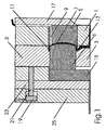
- the device for carrying out the method according to the invention comprises a first mold plate 1 into which a lens insert 5 is inserted.
- the first mold plate 1 is supported on a support plate 17.
- a second mold plate 3 cooperates with the first mold plate 1 and carries an embossing punch 6 which is movable in the axial direction (vertically in the direction of FIG. 1) via a drive plate 15.
- the lens insert 5, the second mold plate 3 and the die 6 form a cavity 7, which can be fed via a sprue 13 with liquid plastic material.
- plastic material also penetrates into the lateral region 11 between the mold plate 3 and the embossing punch 6 and insulates the corresponding end of the embossing punch 6 from the tempered tool. So the material in this area forms a sort of "insulating edge".
- the mold plate 3 is held by a hydraulic device 21. 19 on the mold plate 1 to prevent opening of the mold during filling.
- FIG. 2 shows a representation corresponding to FIG. 1 in two different positions of the embossing punch.
- the die In the position A, the die is set to have a minimum cavity 7a, and the position B shows the maximum cavity die 7b.
- the tool is completely closed and corresponding to a cavity 7a small size set a thin-walled molding.
- plastic plastic material is introduced through an injection cylinder or the screw of an injection molding machine until the minimum cavity is completely filled. This is followed by a short compression phase (optional) to optimally shape the surface at high internal mold pressure.
- the size of the cavity is changed with the linearly displaceable die 6, wherein one end of the die 6 defines the thickness of the cavity and wherein at least along the stroke of the die 6 this end is laterally insulated by injected plastic material against the mold half 3.
- the embossing stamp is insulated from the tempered tool so that it can be axially movable for a long time.
- the thickness of the insulating edge depends on the partial thickness and the resulting cycle time (often 6 minutes and longer). Without insulating edge or too thin insulating edge of the die is braked by the forming cold edge layer on the lens outer edge and would then no longer be axially embossing. The result would be sink marks due to material shrinkage.
- an internal pressure transmitter 9 is preferably present (cf., Fig. 1) in order to determine the internal pressure in the cavity, so that the process can be regulated within the internal pressure.
- the embossing stamp over the entire surface avoids the formation of sink marks and brings full-surface internal pressure to the lens. It is therefore sufficient to produce a lens with little internal pressure and therefore with little frozen tension.
- the usual mold temperatures for thin lenses (2 - 3 mm) in PC are 80 ° C_.
- the mold temperature must therefore be as close as possible to the glass transition temperature during the filling phase. This results in a long cycle time of often more than 6 minutes.
- small cold runner cross sections can be used. Usual is a cold channel thickness, which is equal to the thickness the pre-reduced cavity.
- the lens thickness is produced in the process step (4), ie the inflation of the thin lens. The resulting lens thickness is determined by the amount of injected plastic. It is therefore not necessary to change inserts in the tool to change part wall thicknesses, so that in a tool a variety of lens thicknesses can be produced.
Landscapes
- Engineering & Computer Science (AREA)
- Manufacturing & Machinery (AREA)
- Mechanical Engineering (AREA)
- Health & Medical Sciences (AREA)
- Ophthalmology & Optometry (AREA)
- Moulds For Moulding Plastics Or The Like (AREA)
- Injection Moulding Of Plastics Or The Like (AREA)
- Casting Or Compression Moulding Of Plastics Or The Like (AREA)
Description
- Derartige "dickwandige Formteile" sind beispielsweise Brillengläser, die zum einen aus Glas, andererseits zunehmend auch aus Kunststoff gefertigt werden. Dabei kommen beispielsweise duroplastische Gussmassen (CR39) und Thermoplaste zur Anwendung, wobei je nach Einsatz Polystyrol (PS), Polymethylmethacrylat (PMMA) oder Polycarbonat (PC) verwendet werden; aufgrund der hohen Schlagfähigkeit wird verstärkt PC eingesetzt.
- Bei bekannten Verfahren werden Linsenrohlinge gleichmäßiger Wandstärke (1,5 - 3 mm) in Zykluszeiten von unter 30 s hergestellt, und im Normalfall wird dabei der Standard-Spritzgießprozess verwendet. Die Kunststoffmasse wird in der Füllphase über kleindimensionierte Kanäle in die Linsenkavität eingebracht. Weil amorphe Kunststoffe in der Abkühlphase eine hohe Dichtereduktion (10 - 20 %) erfahren, wird diese Materialschwindung in einer folgenden Nachdruckphase durch Nachfüttem von plastischer Schmelze vom Spritzkolben der Spritzgießmaschine ausgeglichen.
- Bei einem Standard-Sprüzprägeprozess wird im Unterschied zum Standard-Spritzgießprozess die Kunststoffmasse in einer ersten Füllphase in eine vorvergrößerte Kavität eingebracht, und diese Kunststoffmasse wird folgend mittels einer axialen Werkzeugprägung verprägt. Das Massegewicht, das in der ersten Füllphase in die vorvergrößerte Kavität eingebracht wird, entspricht dabei dem Massegewicht der später entnommenen Teile. Mit der axialen Werkzeugbewegung, diese kann sowohl durch Werkzeugtechnik als auch mit Maschinentechnik eingeleitet werden, wird die vorvergrößerte Kavität verkleinert und die Restfüllung der Kavität wird vorgenommen. Das Standard-Spritzprägeverfahren wird eingesetzt für einfache optische Teile wie Linsen, um Einfallstellen als Folge von Materialschwindung zu vermeiden.
- Um bei Linsen mit negativem Brechungsindex (innen dünn, außen dick) Bindenähte zu vermeiden, wird gemäß der
EP 0 144 622 und derUS 4,540,534 in einer ersten Füllphase die Kunststoffmasse in eine vorvergrößerte Kavität eingebracht, bis diese vollständig gefüllt ist. Dann wird folgend eine axiale Werkzeugbewegung eingeleitet, und die vorvergrößerte Kavität wird verkleinert. Eine definierbare Menge Kunststoffmasse wird dabei aus der Kavität verdrängt. Ansonsten entspricht die Vorgehensweise dem Standard-Spritzprägeverfahren. - Eine entsprechende Vorgehensweise wird durch die
US-A-4,828,769 vorgeschlagen. wobei hier die Prägephase beginnt, bevor die erste Einspritzphase abgeschlossen wurde. Auch dieses Verfahren kann für optische Teile verwendet werden; eine bekannte Anwendung ist die Herstellung von DVD. - Die
DE 3414101 A1 offenbart ein Verfahren zum Herstellen von insbesondere dünnwandigen Kunststoff-Formteilen wie beispielsweise Reflektorbauteilen für Signalisieroder Beleuchtungsvorrichtungen für Kraftfahrzeuge. Hierbei wird über einen in der Spritzachse liegenden, zentralen Angusskanal Kunststoffmaterial in eine Kavität veränderbarer Größe eingespritzt und ausgeformt. Bisher wurde dabei ein vorbestimmtes Volumen an Kunststoffmaterial in eine vorvergrößerte Kavität eingespritzt und durch Zufahren der Form ausgeformt, wobei es Probleme gab, die gewünschte Oberflächengüte zu erzielen. Zur Vermeidung dieser Probleme wird gemäß derDE 3414101 A1 vorgeschlagen, in einer ersten Phase die Kavität konstant zu halten und während dieser Phase zunächst einen Vorformling in der Kavität auszubilden. Durch weiteres Einspritzen von Kunststoffmaterial und gleichzeitiges Vergrößern der Kavität durch Zurückziehen eines Kolbens wird der Vorformling in axialer Richtung vergrößert. Wenn der Vorformling die gewünschte Größe erreicht hat, wird der Kolben bis auf einen Anschlag vorgefahren und die Kavität auf die Ausgangsgröße verkleinert, wobei der Vorformling in die Breite gedrückt und das Kunststoff-Formteil ausgeformt wird. Zum Herstellen von dickwandigen optischen Linsen ist dieses Verfahren schon deshalb nicht geeignet, weil durch den in der Spritzachse liegenden Angusskanal Markierungen in der Mitte der Linse auftreten würden. Außerdem kann die Kavität zu keinem Zeitpunkt kleiner gemacht werden als die Größe des Kunststoff-Formteils selbst. - Ein weiteres Verfahren zur Herstellung von optischen Linsen ist aus der gattungsbildenden
GB-A-581197 - Obwohl die oben erwähnten Verfahren befriedigende Ergebnisse bei der Herstellung dünnwandiger Kunststoff-Formteile, beispielsweise dünner Linsen, liefern, ergeben sich erhebliche Probleme bei der Ausbildung von dickwandigen Linsen.
- So können Einfallstellen aufgrund von Materialschwindung auftreten, es können sich Oberflächenmarkierungen ergeben, weil die Kunststoffmasse nicht in einem optimalen Quellfluss in die Kavität einfließen kann. Es können sich kalte Randschichten in der Füllphase verschieben. Durch Erhöhung der Werkzeugtemperatur bis nahe der Glastemperatur (TG = ca. 140°C bei PC) wird die Entstehung von kalten Randschichten unterdrückt. Daraus ergibt sich eine verlängerte Zykluszeit.
- Um einen nahezu optimalen Quellfluss sicherzustellen, werden große Teilanschnitte benötigt, die anschließend staubfrei abgeschnitten werden müssen und in der Regel nicht mehr für die Herstellung von optischen Teilen verwendet werden können und als Abfall entsorgt werden.
- Um eine gute Abformung der Werkzeugkavitätenoberfläche zu erzielen, muss eine hohe Werkzeugtemperatur für die Füllphase gewählt werden. Diese liegt nahe der Glastemperatur des Kunststoffes, so dass damit ein hoher Energieverbrauch verbunden ist.
- Der Erfindung liegt somit die Aufgabe zugrunde, ein Verfahren zum Herstellen von dickwandigen optischen Linsen anzugeben, das sich durch eine wirtschaftliche und einfache Verfahrensführung auszeichnet und mit dem Kunststoff-Formteile mit optimaler Oberflächenbeschaffenheit herstellbar sind.
- Diese Aufgabe wird durch ein Verfahren gemäß Anspruch 1 gelöst; die abhängigen Ansprüche betreffen Weiterentwicklungen der Erfindung.
- Das erfindungsgemäße Verfahren macht sich die Erkenntnis zunutze, dass die Herstellung von relativ dünnwandigen Kunststoff-Formteilen mit guter Oberftächenbeschaffenheit relativ unproblematisch erfolgen kann. Dementsprechend wird diese Erkenntnis auf dickwandige Formteile umgesetzt, und das erfindungsgemäße Verfahren gliedert sich in zwei Phasen. In der ersten Phase wird eine relativ dünnwandige Linse mit optimaler Oberflächenqualität erzeugt, und in einer zweiten Phase wird die Linse auf eine Endwandstärke durch Zufuhr von Kunststoffmaterial "aufgeblasen".
- Nach der ersten Phase oder auch nach der zweiten Phase kann eine Kompressionsphase durchgeführt werden, um Materialschwindung und somit Einfallstellen zu vermeiden.
- Zum Vergrößern der Kavität in der zweiten Phase wird erfindungsgemäß ein Prägestempel eingesetzt, der linear verschieblich ist und einen Teil der Kavität definiert. Dabei ist vorzugsweise der Prägestempel im Bereich seines Formendes, parallel zu seinem Verschiebeweg von der Wandung eines Formwerkzeugs durch eingespritztes Kunststoffmaterial isoliert. Es ist deshalb nicht erforderlich, das Formwerkzeug in dieser Phase auf einer erhöhten Temperatur zu halten.
- Andererseits können jedoch Abkühleffekte in der Kavität nicht vollständig vermieden werden, so dass bei Verwendung eines schneckenwegabhängigen oder schließwegabhängigen Schließkraftprofils der resultierende Innendruck abnehmen würde. Dementsprechend wird erfindungsgemäß vorgeschlagen, ein innendruckgeregeltes Schließkraftprofil zu verwenden.
- Bei der Vorrichtung zur Durchführung des erfindungsgemäßen Verfahrens ist zumindest das kavitätseitige Ende des Prägestempels von einem Hohlraum umgeben, der mit der Kavität kommuniziert und in den eingespritztes Kunststoffmaterial eindringt. Dieser Hohlraum erstreckt sich zumindest über den Hub des verschiebbaren Prägestempels, so dass der Prägestempel von dem Werkzeug zumindest in dem Bereich durch eingedrungenes Kunststoffmaterial isoliert wird.
- Ausführungsformen der Erfindung werden anhand der beigefügten Zeichnungen erläutert. Es zeigen:
- Fig. 1:
- eine schematische Darstellung im Querschnitt der Formvorrichtung,
- Fig. 2A, 2B:
- entsprechende Querschnittsdarstellungen wie die Fig. 1, wobei das Formwerkzeug in zwei verschiedenen Positionen ist,
- Fig. 3:
- ein Prozessablaufdiagramm.
- Gemäß Fig. 1 umfasst die Vorrichtung zur Durchführung des erfindungsgemäßen Verfahrens eine erste Formplatte 1, in die ein Linseneinsatz 5 eingesetzt ist. Die erste Formplatte 1 stützt sich an einer Stützplatte 17 ab. Eine zweite Formplatte 3 wirkt mit der ersten Formplatte 1 zusammen und trägt einen Prägestempel 6, der in Axialrichtung (vertikal Richtung der Fig. 1) über eine Antriebsplatte 15 bewegbar ist. Der Linseneinsatz 5, die zweite Formplatte 3 und der Prägestempel 6 bilden eine Kavität 7, die über einen Anguss 13 mit flüssigem Kunststoffmaterial beschickt werden kann. Dabei dringt insbesondere auch Kunststoffmaterial in den seitlichen Bereich 11 zwischen der Formplatte 3 und dem Prägestempel 6 ein und isoliert das entsprechende Ende des Prägestempels 6 vom temperierten Werkzeug. Das Material in diesem Bereich bildet also gewissermaßen einen "Isolierrand".
- Während des Füllens der Kavität wird die Formplatte 3 durch eine Hydraulikvorrichtung 21. 19 an der Formplatte 1 vorgehalten, um während des Befüllens ein Öffnen der Form zu verhindern.
- Figur 2 zeigt eine der Figur 1 entsprechenden Darstellung in zwei unterschiedlichen Positionen des Prägestempels. In der Stellung A ist der Prägestempel so eingestellt, dass eine minimale Kavität 7a vorhanden ist, und die Stellung B zeigt das Werkzeug mit maximaler Kavität 7b.
- Zur Erläuterung des Prozessablaufs wird auf die Fig. 3 Bezug genommen. Zunächst wird das Werkzeug vollständig geschlossen und eine Kavität 7a geringer Größe entsprechend einem dünnwandigen Formteil eingestellt. In die minimale Kavität 7a wird plastisches Kunststoffmaterial durch einen Spritzzylinder oder die Schnecke einer Spritzgießmaschine eingebracht, bis die minimale Kavität vollständig gefüllt ist. Daran schließt sich eine kurze Kompressionsphase an (optional), um die Oberfläche bei hohem Forminnendruck optimal abzuformen.
- Anschließend wird durch fortgesetztes Einspritzen von Kunststoffmaterial und gleichzeitiges Vergrößern der Kavität, bis eine Kavität 7b entsprechend dem gewünschten dickwandigen Kunststoff-Formteil erreicht ist, die Kunststoffmasse von Spritzzylinder der Spritzgießmaschine bis zum Erreichen einer definierten Teilwandstärke "aufgeblasen", und zwar optional schneckenwegabhängig oder schließenwegabhängig. Daran schließt sich eine Prägephase an, in der zur Vermeidung von Einfallstellen infolge von Materialschwindung eine Massenkompression durchgeführt wird. Nach dem Ausformen des Kunststoff-Formteils kann die Form geöffnet und das Kunststoff-Formteil entnommen werden, woran sich ein weiterer Zyklus anschließt.
- Die Größe der Kavität wird mit dem linear verschiebbaren Prägestempel 6 geändert, wobei ein Ende des Prägestempels 6 die Dicke der Kavität definiert und wobei man mindestens entlang des Hubs des Prägestempels 6 dieses Ende seitlich durch eingespritztes Kunststoffmaterial thermisch gegen die Formhälfte 3 isoliert. Durch den erfindungsgemäßen "Isolierrand" wird der Prägestempel vom temperierten Werkzeug isoliert, so dass er lange Zeit axial beweglich sein kann. Die Dicke des Isolierrandes ist abhängig von der Teildicke und der daraus resultierenden Zykluszeit (oft 6 Min. und länger). Ohne Isolierrand oder zu dünnem Isolierrand wird der Prägestempel durch die sich bildende kalte Randschicht am Linsenaußenrand gebremst und wäre dann nicht mehr axial prägefähig. Die Folge wären Einfallstellen infolge Materialschwindung.
- Um weiterhin Einfallstellen zu vermeiden, ist es wichtig, dass der Innendruck der Kavität möglichst konstant ist. Aus diesem Grund ist vorzugsweise ein Innendruckgeber 9 vorhanden (vgl. Fig. 1), um den Innendruck in der Kavität zu ermitteln, so dass der Prozess innendruckabhängig geregelt werden kann.
- Bei dem erfindungsgemäßen Verfahren ergeben sich diverse Vorteile im Vergleich mit dem Stand der Technik. So gibt es wegen der abschließenden Prägephase im Ablaufschritt (5) keine Materialschwindung und somit ergeben sich keine Einfallstellen.
- Durch die abschließende Prägephase (5) vermeidet der Prägestempel vollflächig die Bildung von Einfallstellen und bringt vollflächig Innendruck auf die Linse. Es reicht somit aus, eine Linse mit wenig Innendruck und deshalb mit wenig eingefrorenen Spannungen herzustellen.
- Die üblichen Werkzeugtemperaturen bei dünnen Linsen (2 - 3 mm) in PC liegen bei 80°C_ Die bei dicken Linsen (13 mm) liegen bei ca. 120°C. Diese hohe Temperatur wird benötigt, damit die resultierenden Fehler wie "Verschieben von kalten Randschichten" und fehlende Oberflächenbrillanz zu vermeiden. Die Werkzeugtemperatur muss deshalb während der Füllphase so nahe wie möglich bei der Glastemperatur liegen. Es ergibt sich eine lange Zykluszeit von oft mehr als 6 Minuten.
- Anders bei dem neuen Verfahren. Hier bildet sich bereits in der Füllphase ein Innendruck in der Kavität infolge des Füllwiderstandes. Bereits mit Werkzeugtemperaturen von ca. 80°C (bei PC) erfolgt kein Verschieben von kalten Randschichten und es ergibt sich eine optimale Oberflächenausprägung und damit eine hohe Oberflächenbrillanz. Eine Reduktion der Zykluszeit um bis zu 50 % ist erreichbar.
- Wegen der dünnen Wandstärken der vorverkleinerten Kavität bildet sich auch bei niederviskosen Kunststoffen ein optimaler Quellfluss. Es ist deshalb möglich, kleine Anschnitte (Punktanschnitt, Tunnelanschnitt) zu verwenden. Der Kaltkanal kann deshalb nach der Teilentformung (Punktanschnitt) leicht von der Linse getrennt werden. Am Beispiel Tunnelanschnitt ist auch eine automatische Trennung des Kaltkanals bei der Werkzeugöffnung möglich.
- Weil auf den Schwindungsausgleich durch den Spritzzylinder der Spritzgießmaschine vollständig verzichtet werden kann und weil die Ablaufschritte bis zum abschließenden Prägen innerhalb kurzer Zeit (7 Sekunden) abgeschlossen sind, können kleine Kaltkanalquerschnitte verwendet werden. Üblich ist eine Kaltkanaldicke, die gleich der Dicke der vorverkleinerten Kavität ist. Die Linsendicke wird im Ablaufschritt (4), d. h. dem Aufblasen der dünnen Linse, hergestellt. Die resultierende Linsendicke ergibt sich durch die Menge des eingespritzten Kunststoffs. Es ist also nicht erforderlich, Einsätze im Werkzeug zu wechseln, um Teilwandstärken zu ändern, so dass in einem Werkzeug eine Vielzahl von Linsendicken hergestellt werden kann.
Claims (4)
- Verfahren zum Herstellen dickwandiger optischer Linsen durch Einspritzen von Kunststoffmaterial in eine Form mit veränderbarer Kavität,
dadurch gekennzeichnet,
dass in einer ersten Phase eine relativ dünnwandige Linse mit optimaler Oberflächenqualität erzeugt wird und dass in einer zweiten Phase die Linse auf eine Endwandstärke durch Zufuhr von Kunststoffmaterial aufgeblasen wird. - Verfahren nach Anspruch 1.
dadurch gekennzeichnet,
dass nach der ersten Phase und/oder nach der zweiten Phase eine Kompressionsphase durchgeführt wird. - Verfahren nach Anspruch 1 oder 2,
dadurch gekennzeichnet,
dass man den Innendruck in der Kavität ermittelt und die Größe der Kavität mit einem linear verschiebbaren Prägestempel ändert, wobei der Innendruck in der Kavität möglichst konstant gehalten wird. - Verfahren nach Anspruch 3,
dadurch gekennzeichnet,
dass ein Ende des Prägestempels die Dicke der Kavität definiert und dass man mindestens entlang des Hubs des Prägestempels dieses Ende seitlich durch eingespritztes Kunststoffmaterial thermisch gegen eine Formhälfte isoliert
Applications Claiming Priority (3)
| Application Number | Priority Date | Filing Date | Title |
|---|---|---|---|
| DE10048861 | 2000-10-02 | ||
| DE10048861A DE10048861A1 (de) | 2000-10-02 | 2000-10-02 | Verfahren und Vorrichtung zum Herstellen von dickwandigen Formteilen |
| EP01986636A EP1332033B1 (de) | 2000-10-02 | 2001-09-28 | Verfahren und vorrichtung zum herstellen von dickwandingen formteilen |
Related Parent Applications (2)
| Application Number | Title | Priority Date | Filing Date |
|---|---|---|---|
| EP01986636A Division EP1332033B1 (de) | 2000-10-02 | 2001-09-28 | Verfahren und vorrichtung zum herstellen von dickwandingen formteilen |
| EP01986636.7 Division | 2001-09-28 |
Publications (3)
| Publication Number | Publication Date |
|---|---|
| EP1533099A2 EP1533099A2 (de) | 2005-05-25 |
| EP1533099A3 EP1533099A3 (de) | 2005-08-31 |
| EP1533099B1 true EP1533099B1 (de) | 2007-10-31 |
Family
ID=7658488
Family Applications (2)
| Application Number | Title | Priority Date | Filing Date |
|---|---|---|---|
| EP05004302A Expired - Lifetime EP1533099B1 (de) | 2000-10-02 | 2001-09-28 | Verfahren zum Herstellen von dickwandigen Formteilen |
| EP01986636A Expired - Lifetime EP1332033B1 (de) | 2000-10-02 | 2001-09-28 | Verfahren und vorrichtung zum herstellen von dickwandingen formteilen |
Family Applications After (1)
| Application Number | Title | Priority Date | Filing Date |
|---|---|---|---|
| EP01986636A Expired - Lifetime EP1332033B1 (de) | 2000-10-02 | 2001-09-28 | Verfahren und vorrichtung zum herstellen von dickwandingen formteilen |
Country Status (9)
| Country | Link |
|---|---|
| US (1) | US20030164564A1 (de) |
| EP (2) | EP1533099B1 (de) |
| JP (1) | JP4646181B2 (de) |
| CN (1) | CN1273281C (de) |
| AT (3) | ATE376919T1 (de) |
| CA (1) | CA2424422C (de) |
| DE (4) | DE10048861A1 (de) |
| TW (1) | TW537957B (de) |
| WO (1) | WO2002030651A1 (de) |
Families Citing this family (20)
| Publication number | Priority date | Publication date | Assignee | Title |
|---|---|---|---|---|
| DE10141858B4 (de) * | 2001-08-27 | 2010-06-17 | Kraussmaffei Technologies Gmbh | Verfahren und Vorrichtung zum Herstellen flächenartiger Kunststoff-Formteile, insbesondere Kunststoffscheiben |
| DE102004036171A1 (de) * | 2004-07-26 | 2006-03-23 | Angell-Demmel Gmbh | Verfahren und Vorrichtung zur Herstellung eines Dekor-Zierteils mit freigestelltem Symbol |
| DE102004051250A1 (de) * | 2004-10-20 | 2006-04-27 | Demag Ergotech Gmbh | Verfahren zum Herstellen von langfaserverstärkten Kunststoffformteilen |
| DE102004051292B3 (de) * | 2004-10-20 | 2006-08-03 | Karl Hehl | Verfahren zum Spritzgießen von Spritzteilen mit einem Prägeablauf |
| WO2006050230A2 (en) * | 2004-10-28 | 2006-05-11 | Nypro Inc. | System, device, and method for producing thin plastic lenses |
| DE102007011338A1 (de) | 2007-03-06 | 2008-09-11 | Jenoptik Polymer Systems Gmbh | Verfahren und Vorrichtung zum Herstellen von dickwandigen optischen Formteilen |
| KR20100027115A (ko) * | 2007-06-01 | 2010-03-10 | 사빅 이노베이티브 플라스틱스 아이피 비.브이. | 오버 몰드된 두꺼운 벽 부품 |
| ES2398608T3 (es) * | 2008-09-15 | 2013-03-20 | Momexx B.V. | Aparato y procedimiento para controlar el moldeo de inyección compresión |
| JP2010256670A (ja) * | 2009-04-27 | 2010-11-11 | Konica Minolta Sensing Inc | 回折格子およびそれを用いる分光ユニット、分光計ならびに回折格子の作成方法 |
| DE102009027646A1 (de) | 2009-07-13 | 2011-01-20 | Evonik Röhm Gmbh | Vorrichtung und Verfahren zur Herstellung dickwandiger Kunststoffformteile mit verringerten Einfallstellen durch Spritzgießen oder -prägen |
| DE102011115591A1 (de) | 2011-10-11 | 2013-04-11 | Kraussmaffei Technologies Gmbh | Verfahren zum Beschichten eines Formteils |
| DE102015116402A1 (de) * | 2015-09-28 | 2017-03-30 | Carl Zeiss Smart Optics Gmbh | Optisches Bauteil und Verfahren zu seiner Herstellung |
| DE102015117309A1 (de) | 2015-10-12 | 2017-04-13 | Kraussmaffei Technologies Gmbh | Spritzgießmaschine aufweisend eine Beschichtungsanlage |
| WO2017166543A1 (zh) * | 2016-04-01 | 2017-10-05 | 上海小糸车灯有限公司 | 厚壁塑件包围式分层注塑方法及其模具结构和配光镜产品 |
| CN108099114A (zh) * | 2017-12-22 | 2018-06-01 | 台州市黄岩宇亚模具有限公司 | 一种多次注塑模具及其使用方法 |
| DE102018111545A1 (de) * | 2018-05-15 | 2019-11-21 | HELLA GmbH & Co. KGaA | Verfahren zur Herstellung einer optischen Linse und mit dem Verfahren hergestellte optische Linse |
| CN112406043B (zh) * | 2020-09-24 | 2024-08-13 | 中昊晨光化工研究院有限公司 | 一种制造塑料制品的模具 |
| JP7589008B2 (ja) * | 2020-10-23 | 2024-11-25 | 株式会社日本製鋼所 | 射出圧縮成形方法、射出装置および射出成形機 |
| CN112895335B (zh) * | 2021-04-01 | 2025-08-19 | 广东旭业光电科技股份有限公司 | 一种可调节光学镜片模具及方法 |
| EP4079481A1 (de) * | 2021-04-22 | 2022-10-26 | Essilor International | Verfahren und vorrichtung zum einstellen der vertiefungstiefe eines formeinsatzes |
Family Cites Families (16)
| Publication number | Priority date | Publication date | Assignee | Title |
|---|---|---|---|---|
| GB581197A (en) * | 1944-06-23 | 1946-10-03 | John Johnson | Improvements in the manufacture of lenses |
| DE2702412A1 (de) * | 1977-01-21 | 1978-07-27 | Weber Hermann P | Verfahren und vorrichtung zum spritzgiessen von linsen |
| JPS5953858B2 (ja) * | 1978-05-13 | 1984-12-27 | ダイセル化学工業株式会社 | 度付レンズの成形方法 |
| US4363772A (en) * | 1979-07-16 | 1982-12-14 | Hidding Daniel P | Method and apparatus for injection molding utilizing expandable cavity |
| FR2545033B1 (fr) * | 1983-04-28 | 1985-08-16 | Cibie Projecteurs | Procede et dispositif pour la realisation de pieces en matiere plastique, sur presse a injection |
| US4540534A (en) * | 1983-10-11 | 1985-09-10 | American Optical Corporation | Apparatus and method for injection molding lenses |
| US4828769A (en) * | 1986-05-05 | 1989-05-09 | Galic/Maus Ventures | Method for injection molding articles |
| IT1232661B (it) * | 1988-03-02 | 1992-03-02 | Pilkington Visioncare Holdings | Procedimento e apparecchio di stampaggio e colata utilizzando matrici a bocchello aventi superfici di stampaggio parametriche |
| WO1991008890A1 (en) * | 1989-12-08 | 1991-06-27 | Philips And Du Pont Optical Company | Apparatus and method for controlling an injection molding process producing a molded part |
| JP2508908B2 (ja) * | 1990-09-28 | 1996-06-19 | 住友化学工業株式会社 | 熱可塑性樹脂のプレス成形方法 |
| DE4301320C1 (de) * | 1993-01-20 | 1994-05-05 | Peguform Werke Gmbh | Spritzgießform zur Herstellung von Kunststoffteilen |
| JPH09277335A (ja) * | 1996-02-16 | 1997-10-28 | Idemitsu Petrochem Co Ltd | ガラス繊維強化熱可塑性樹脂軽量成形品の製造法及び軽量成形品 |
| DE69735855T2 (de) * | 1996-02-16 | 2006-09-14 | Idemitsu Kosan Co. Ltd. | Verfahren zum herstellen eines leichten, faserverstärkten gegenstands aus thermoplastischem harz und leichtes formprodukt |
| AU720148B2 (en) * | 1996-09-05 | 2000-05-25 | Wea Manufacturing Inc. | Injection molding of compact discs |
| GB9711048D0 (en) * | 1997-05-30 | 1997-07-23 | Kontor Moulding Systems Ltd | Injection moulding of thermoplastic polymer |
| DE19843921B4 (de) * | 1998-09-24 | 2007-12-27 | Krauss Maffei Gmbh | Verfahren zum Herstellen von Verbund-Kunststoffformteilen durch Spritzprägen |
-
2000
- 2000-10-02 DE DE10048861A patent/DE10048861A1/de not_active Withdrawn
- 2000-10-02 DE DE10066272A patent/DE10066272B4/de not_active Expired - Fee Related
-
2001
- 2001-09-28 JP JP2002534059A patent/JP4646181B2/ja not_active Expired - Fee Related
- 2001-09-28 EP EP05004302A patent/EP1533099B1/de not_active Expired - Lifetime
- 2001-09-28 CN CNB018165184A patent/CN1273281C/zh not_active Expired - Fee Related
- 2001-09-28 EP EP01986636A patent/EP1332033B1/de not_active Expired - Lifetime
- 2001-09-28 WO PCT/EP2001/011262 patent/WO2002030651A1/de not_active Ceased
- 2001-09-28 CA CA2424422A patent/CA2424422C/en not_active Expired - Fee Related
- 2001-09-28 DE DE50113209T patent/DE50113209D1/de not_active Expired - Lifetime
- 2001-09-28 AT AT05004302T patent/ATE376919T1/de active
- 2001-09-28 DE DE50105557T patent/DE50105557D1/de not_active Expired - Lifetime
- 2001-09-28 AT AT01986636T patent/ATE290458T1/de active
- 2001-10-02 TW TW090124315A patent/TW537957B/zh not_active IP Right Cessation
-
2003
- 2003-03-31 US US10/403,545 patent/US20030164564A1/en not_active Abandoned
-
2005
- 2005-03-29 AT AT0018805U patent/AT8231U1/de not_active IP Right Cessation
Also Published As
| Publication number | Publication date |
|---|---|
| JP2004510607A (ja) | 2004-04-08 |
| DE10066272B4 (de) | 2009-01-29 |
| EP1332033A1 (de) | 2003-08-06 |
| EP1332033B1 (de) | 2005-03-09 |
| TW537957B (en) | 2003-06-21 |
| DE50105557D1 (de) | 2005-04-14 |
| EP1533099A2 (de) | 2005-05-25 |
| US20030164564A1 (en) | 2003-09-04 |
| CA2424422A1 (en) | 2003-04-01 |
| ATE376919T1 (de) | 2007-11-15 |
| AT8231U1 (de) | 2006-04-15 |
| DE10048861A1 (de) | 2002-04-25 |
| CN1273281C (zh) | 2006-09-06 |
| EP1533099A3 (de) | 2005-08-31 |
| ATE290458T1 (de) | 2005-03-15 |
| CA2424422C (en) | 2010-06-08 |
| DE50113209D1 (de) | 2007-12-13 |
| HK1060329A1 (en) | 2004-08-06 |
| JP4646181B2 (ja) | 2011-03-09 |
| CN1466511A (zh) | 2004-01-07 |
| WO2002030651A1 (de) | 2002-04-18 |
Similar Documents
| Publication | Publication Date | Title |
|---|---|---|
| DE10066272B4 (de) | Verfahren und Vorrichtung zum Herstellen von dickwandigen Formteilen | |
| EP2697030B1 (de) | Verfahren zur herstellung von mehrschichtigen kunststoff-formteilen aus einem einheitlichen thermoplastischen kunststoff | |
| AT395693B (de) | Einrichtung zum spritzpressen | |
| DE68929311T2 (de) | Verfahren zum einspritzgiessformen | |
| DE19534982C2 (de) | Verfahren zum Spritzgießen von thermoplastischen Harzen | |
| DE60201175T2 (de) | Formwerkzeug und verfahren zum spritzprägen | |
| EP0791448A2 (de) | Verfahren und Vorrichtung zum Spritzgiessen von Kunststoffteilen | |
| EP2454070A1 (de) | Vorrichtung und verfahren zur herstellung dickwandiger kunststoffformteile mit verringerten einfallstellen durch spritzgiessen oder prägen | |
| DD285570A5 (de) | Spritzgussverfahren und spritzgussvorrichtung | |
| DE3886510T2 (de) | Verfahren und System zum von lokalem Fluidium assistierten Spritzgiessen und dadurch hergstellter Körper. | |
| EP0824057A1 (de) | Verfahren und Vorrichtung zur Herstellung von Spritzgussteilen aus Kunststoff | |
| EP0696954B1 (de) | Vorrichtung zur herstellung eines grossflächigen kunststoffgegenstandes geringer wanddicke | |
| DE69705570T2 (de) | Spritzprägeverfahren zum Formen von Linsen | |
| EP1282500A1 (de) | Verfahren und vorrichtung zur herstellung eines formteils aus einem metall-/kunststoffverbund sowie verwendung der vorrichtung | |
| DE2932499A1 (de) | Verfahren und vorrichtung zum giessen eines gegenstandes, insbesondere einer linse, aus kunstharz | |
| DE10141858B4 (de) | Verfahren und Vorrichtung zum Herstellen flächenartiger Kunststoff-Formteile, insbesondere Kunststoffscheiben | |
| WO2007096144A2 (de) | Verfahren zur herstellung von dünnwandigen kunststoff-formteilen | |
| EP1233857B1 (de) | Verfahren und vorrichtung zum herstellen eines kunststoffformteils, welches mehrere felder umfasst | |
| DE10356984A1 (de) | Kunststoffdruckguss-Gegenstände mit Hohlrippenelementen | |
| EP1420930B1 (de) | Verfahren und vorrichtung zum automatischen herstellen dünner platten | |
| DE10202246A1 (de) | Vorrichtung und Verfahren zum Herstellen optischer Formteile aus Kunstoff | |
| DE10342360B4 (de) | Vorrichtung und Verfahren zum Fertigen eines zwei- oder mehrkomponentigen Kunstoff-Spritzgießteils mittels eines Prägeverfahrens | |
| EP1912773B1 (de) | Verfahren, steuerung für eine maschine und computerprogrammprodukt zur steuerung einer maschine zur herstellung eines formteils, insbesondere spritzgiessverfahren | |
| DE10302102B3 (de) | Verfahren und Vorrichtung zum Herstellen von Formteilen aus Kunststoff | |
| EP1440782B1 (de) | Vorrichtung und Verfahren zur Herstellung von aus Kunststoff bestehenden Gegenständen (Kunststoffbauteilen) mittels Fliessbremsen in Spritzgusswerkzeugen und deren Verwendung |
Legal Events
| Date | Code | Title | Description |
|---|---|---|---|
| PUAI | Public reference made under article 153(3) epc to a published international application that has entered the european phase |
Free format text: ORIGINAL CODE: 0009012 |
|
| AC | Divisional application: reference to earlier application |
Ref document number: 1332033 Country of ref document: EP Kind code of ref document: P |
|
| AK | Designated contracting states |
Kind code of ref document: A2 Designated state(s): AT BE CH CY DE DK ES FI FR GB GR IE IT LI LU MC NL PT SE TR |
|
| PUAL | Search report despatched |
Free format text: ORIGINAL CODE: 0009013 |
|
| AK | Designated contracting states |
Kind code of ref document: A3 Designated state(s): AT BE CH CY DE DK ES FI FR GB GR IE IT LI LU MC NL PT SE TR |
|
| 17P | Request for examination filed |
Effective date: 20050726 |
|
| AKX | Designation fees paid |
Designated state(s): AT BE CH CY DE DK ES FI FR GB GR IE IT LI LU MC NL PT SE TR |
|
| GRAP | Despatch of communication of intention to grant a patent |
Free format text: ORIGINAL CODE: EPIDOSNIGR1 |
|
| RTI1 | Title (correction) |
Free format text: METHOD FOR PRODUCING THICK-WALLED MOULDED PARTS |
|
| RAP1 | Party data changed (applicant data changed or rights of an application transferred) |
Owner name: KRAUSS MAFFEI GMBH |
|
| GRAS | Grant fee paid |
Free format text: ORIGINAL CODE: EPIDOSNIGR3 |
|
| GRAA | (expected) grant |
Free format text: ORIGINAL CODE: 0009210 |
|
| AC | Divisional application: reference to earlier application |
Ref document number: 1332033 Country of ref document: EP Kind code of ref document: P |
|
| AK | Designated contracting states |
Kind code of ref document: B1 Designated state(s): AT BE CH CY DE DK ES FI FR GB GR IE IT LI LU MC NL PT SE TR |
|
| REG | Reference to a national code |
Ref country code: GB Ref legal event code: FG4D Free format text: NOT ENGLISH |
|
| REG | Reference to a national code |
Ref country code: IE Ref legal event code: FG4D Free format text: LANGUAGE OF EP DOCUMENT: GERMAN |
|
| REG | Reference to a national code |
Ref country code: CH Ref legal event code: NV Representative=s name: KIRKER & CIE S.A. Ref country code: CH Ref legal event code: EP |
|
| REF | Corresponds to: |
Ref document number: 50113209 Country of ref document: DE Date of ref document: 20071213 Kind code of ref document: P |
|
| RAP2 | Party data changed (patent owner data changed or rights of a patent transferred) |
Owner name: KRAUSMAFFEI TECHNOLOGIES GMBH |
|
| RAP2 | Party data changed (patent owner data changed or rights of a patent transferred) |
Owner name: KRAUSSMAFFEI TECHNOLOGIES GMBH |
|
| NLT2 | Nl: modifications (of names), taken from the european patent patent bulletin |
Owner name: KRAUSMAFFEI TECHNOLOGIES GMBH Effective date: 20080102 |
|
| NLV1 | Nl: lapsed or annulled due to failure to fulfill the requirements of art. 29p and 29m of the patents act | ||
| PG25 | Lapsed in a contracting state [announced via postgrant information from national office to epo] |
Ref country code: NL Free format text: LAPSE BECAUSE OF FAILURE TO SUBMIT A TRANSLATION OF THE DESCRIPTION OR TO PAY THE FEE WITHIN THE PRESCRIBED TIME-LIMIT Effective date: 20071031 Ref country code: ES Free format text: LAPSE BECAUSE OF FAILURE TO SUBMIT A TRANSLATION OF THE DESCRIPTION OR TO PAY THE FEE WITHIN THE PRESCRIBED TIME-LIMIT Effective date: 20080211 Ref country code: SE Free format text: LAPSE BECAUSE OF FAILURE TO SUBMIT A TRANSLATION OF THE DESCRIPTION OR TO PAY THE FEE WITHIN THE PRESCRIBED TIME-LIMIT Effective date: 20080131 |
|
| GBV | Gb: ep patent (uk) treated as always having been void in accordance with gb section 77(7)/1977 [no translation filed] | ||
| PG25 | Lapsed in a contracting state [announced via postgrant information from national office to epo] |
Ref country code: PT Free format text: LAPSE BECAUSE OF FAILURE TO SUBMIT A TRANSLATION OF THE DESCRIPTION OR TO PAY THE FEE WITHIN THE PRESCRIBED TIME-LIMIT Effective date: 20080331 |
|
| REG | Reference to a national code |
Ref country code: IE Ref legal event code: FD4D |
|
| ET | Fr: translation filed | ||
| PG25 | Lapsed in a contracting state [announced via postgrant information from national office to epo] |
Ref country code: DK Free format text: LAPSE BECAUSE OF FAILURE TO SUBMIT A TRANSLATION OF THE DESCRIPTION OR TO PAY THE FEE WITHIN THE PRESCRIBED TIME-LIMIT Effective date: 20071031 |
|
| PLBI | Opposition filed |
Free format text: ORIGINAL CODE: 0009260 |
|
| PLAX | Notice of opposition and request to file observation + time limit sent |
Free format text: ORIGINAL CODE: EPIDOSNOBS2 |
|
| 26 | Opposition filed |
Opponent name: ENGEL AUSTRIA GMBH Effective date: 20080731 |
|
| PG25 | Lapsed in a contracting state [announced via postgrant information from national office to epo] |
Ref country code: IE Free format text: LAPSE BECAUSE OF FAILURE TO SUBMIT A TRANSLATION OF THE DESCRIPTION OR TO PAY THE FEE WITHIN THE PRESCRIBED TIME-LIMIT Effective date: 20071031 |
|
| PG25 | Lapsed in a contracting state [announced via postgrant information from national office to epo] |
Ref country code: GB Free format text: LAPSE BECAUSE OF FAILURE TO SUBMIT A TRANSLATION OF THE DESCRIPTION OR TO PAY THE FEE WITHIN THE PRESCRIBED TIME-LIMIT Effective date: 20071031 |
|
| PLAF | Information modified related to communication of a notice of opposition and request to file observations + time limit |
Free format text: ORIGINAL CODE: EPIDOSCOBS2 |
|
| PG25 | Lapsed in a contracting state [announced via postgrant information from national office to epo] |
Ref country code: GR Free format text: LAPSE BECAUSE OF FAILURE TO SUBMIT A TRANSLATION OF THE DESCRIPTION OR TO PAY THE FEE WITHIN THE PRESCRIBED TIME-LIMIT Effective date: 20080201 |
|
| PG25 | Lapsed in a contracting state [announced via postgrant information from national office to epo] |
Ref country code: FI Free format text: LAPSE BECAUSE OF FAILURE TO SUBMIT A TRANSLATION OF THE DESCRIPTION OR TO PAY THE FEE WITHIN THE PRESCRIBED TIME-LIMIT Effective date: 20071031 |
|
| PLBB | Reply of patent proprietor to notice(s) of opposition received |
Free format text: ORIGINAL CODE: EPIDOSNOBS3 |
|
| BERE | Be: lapsed |
Owner name: KRAUSS MAFFEI G.M.B.H. Effective date: 20080930 |
|
| PG25 | Lapsed in a contracting state [announced via postgrant information from national office to epo] |
Ref country code: MC Free format text: LAPSE BECAUSE OF NON-PAYMENT OF DUE FEES Effective date: 20080930 |
|
| PG25 | Lapsed in a contracting state [announced via postgrant information from national office to epo] |
Ref country code: CY Free format text: LAPSE BECAUSE OF FAILURE TO SUBMIT A TRANSLATION OF THE DESCRIPTION OR TO PAY THE FEE WITHIN THE PRESCRIBED TIME-LIMIT Effective date: 20071031 Ref country code: BE Free format text: LAPSE BECAUSE OF NON-PAYMENT OF DUE FEES Effective date: 20080930 |
|
| PLCK | Communication despatched that opposition was rejected |
Free format text: ORIGINAL CODE: EPIDOSNREJ1 |
|
| PG25 | Lapsed in a contracting state [announced via postgrant information from national office to epo] |
Ref country code: LU Free format text: LAPSE BECAUSE OF NON-PAYMENT OF DUE FEES Effective date: 20080928 |
|
| PG25 | Lapsed in a contracting state [announced via postgrant information from national office to epo] |
Ref country code: TR Free format text: LAPSE BECAUSE OF FAILURE TO SUBMIT A TRANSLATION OF THE DESCRIPTION OR TO PAY THE FEE WITHIN THE PRESCRIBED TIME-LIMIT Effective date: 20071031 |
|
| APBM | Appeal reference recorded |
Free format text: ORIGINAL CODE: EPIDOSNREFNO |
|
| APBP | Date of receipt of notice of appeal recorded |
Free format text: ORIGINAL CODE: EPIDOSNNOA2O |
|
| APAH | Appeal reference modified |
Free format text: ORIGINAL CODE: EPIDOSCREFNO |
|
| APBQ | Date of receipt of statement of grounds of appeal recorded |
Free format text: ORIGINAL CODE: EPIDOSNNOA3O |
|
| REG | Reference to a national code |
Ref country code: AT Ref legal event code: HC Ref document number: 376919 Country of ref document: AT Kind code of ref document: T Owner name: KRAUSSMAFFEI TECHNOLOGIES GMBH, DE Effective date: 20121116 |
|
| REG | Reference to a national code |
Ref country code: DE Ref legal event code: R082 Ref document number: 50113209 Country of ref document: DE Representative=s name: WILHELM, LUDWIG, DIPL.-PHYS., DE |
|
| REG | Reference to a national code |
Ref country code: DE Ref legal event code: R081 Ref document number: 50113209 Country of ref document: DE Owner name: KRAUSSMAFFEI TECHNOLOGIES GMBH, DE Free format text: FORMER OWNER: KRAUSSMAFFEI TECHNOLOGIES GMBH, 80997 MUENCHEN, DE Effective date: 20130603 Ref country code: DE Ref legal event code: R082 Ref document number: 50113209 Country of ref document: DE Representative=s name: WILHELM, LUDWIG, DIPL.-PHYS., DE Effective date: 20130603 |
|
| REG | Reference to a national code |
Ref country code: DE Ref legal event code: R100 Ref document number: 50113209 Country of ref document: DE |
|
| APBU | Appeal procedure closed |
Free format text: ORIGINAL CODE: EPIDOSNNOA9O |
|
| PLBN | Opposition rejected |
Free format text: ORIGINAL CODE: 0009273 |
|
| STAA | Information on the status of an ep patent application or granted ep patent |
Free format text: STATUS: OPPOSITION REJECTED |
|
| 27O | Opposition rejected |
Effective date: 20150107 |
|
| REG | Reference to a national code |
Ref country code: AT Ref legal event code: PC Ref document number: 376919 Country of ref document: AT Kind code of ref document: T Owner name: KRAUSSMAFFEI TECHNOLOGIES GMBH, DE Effective date: 20160706 |
|
| REG | Reference to a national code |
Ref country code: FR Ref legal event code: PLFP Year of fee payment: 16 |
|
| REG | Reference to a national code |
Ref country code: FR Ref legal event code: PLFP Year of fee payment: 17 |
|
| REG | Reference to a national code |
Ref country code: FR Ref legal event code: PLFP Year of fee payment: 18 |
|
| PGFP | Annual fee paid to national office [announced via postgrant information from national office to epo] |
Ref country code: CH Payment date: 20180919 Year of fee payment: 18 |
|
| PGFP | Annual fee paid to national office [announced via postgrant information from national office to epo] |
Ref country code: DE Payment date: 20190918 Year of fee payment: 19 Ref country code: FR Payment date: 20190925 Year of fee payment: 19 Ref country code: IT Payment date: 20190925 Year of fee payment: 19 |
|
| PGFP | Annual fee paid to national office [announced via postgrant information from national office to epo] |
Ref country code: AT Payment date: 20190919 Year of fee payment: 19 |
|
| REG | Reference to a national code |
Ref country code: CH Ref legal event code: PL |
|
| PG25 | Lapsed in a contracting state [announced via postgrant information from national office to epo] |
Ref country code: CH Free format text: LAPSE BECAUSE OF NON-PAYMENT OF DUE FEES Effective date: 20190930 Ref country code: LI Free format text: LAPSE BECAUSE OF NON-PAYMENT OF DUE FEES Effective date: 20190930 |
|
| REG | Reference to a national code |
Ref country code: DE Ref legal event code: R119 Ref document number: 50113209 Country of ref document: DE |
|
| REG | Reference to a national code |
Ref country code: AT Ref legal event code: MM01 Ref document number: 376919 Country of ref document: AT Kind code of ref document: T Effective date: 20200928 |
|
| PG25 | Lapsed in a contracting state [announced via postgrant information from national office to epo] |
Ref country code: FR Free format text: LAPSE BECAUSE OF NON-PAYMENT OF DUE FEES Effective date: 20200930 Ref country code: DE Free format text: LAPSE BECAUSE OF NON-PAYMENT OF DUE FEES Effective date: 20210401 |
|
| PG25 | Lapsed in a contracting state [announced via postgrant information from national office to epo] |
Ref country code: AT Free format text: LAPSE BECAUSE OF NON-PAYMENT OF DUE FEES Effective date: 20200928 |
|
| PG25 | Lapsed in a contracting state [announced via postgrant information from national office to epo] |
Ref country code: IT Free format text: LAPSE BECAUSE OF NON-PAYMENT OF DUE FEES Effective date: 20200928 |