EP1533178A2 - Dispositif de commande pour l' hayon élévateur - Google Patents
Dispositif de commande pour l' hayon élévateur Download PDFInfo
- Publication number
- EP1533178A2 EP1533178A2 EP04025146A EP04025146A EP1533178A2 EP 1533178 A2 EP1533178 A2 EP 1533178A2 EP 04025146 A EP04025146 A EP 04025146A EP 04025146 A EP04025146 A EP 04025146A EP 1533178 A2 EP1533178 A2 EP 1533178A2
- Authority
- EP
- European Patent Office
- Prior art keywords
- operating device
- cover
- control
- panels
- housing
- Prior art date
- Legal status (The legal status is an assumption and is not a legal conclusion. Google has not performed a legal analysis and makes no representation as to the accuracy of the status listed.)
- Granted
Links
- 230000005484 gravity Effects 0.000 claims description 13
- 210000000056 organ Anatomy 0.000 claims description 4
- 230000033001 locomotion Effects 0.000 description 3
- 239000004033 plastic Substances 0.000 description 2
- 239000002313 adhesive film Substances 0.000 description 1
- 238000005286 illumination Methods 0.000 description 1
- 238000004519 manufacturing process Methods 0.000 description 1
- 239000000463 material Substances 0.000 description 1
- 230000001360 synchronised effect Effects 0.000 description 1
- 230000029305 taxis Effects 0.000 description 1
- 229920001169 thermoplastic Polymers 0.000 description 1
- 239000004416 thermosoftening plastic Substances 0.000 description 1
Images
Classifications
-
- B—PERFORMING OPERATIONS; TRANSPORTING
- B60—VEHICLES IN GENERAL
- B60P—VEHICLES ADAPTED FOR LOAD TRANSPORTATION OR TO TRANSPORT, TO CARRY, OR TO COMPRISE SPECIAL LOADS OR OBJECTS
- B60P1/00—Vehicles predominantly for transporting loads and modified to facilitate loading, consolidating the load, or unloading
- B60P1/44—Vehicles predominantly for transporting loads and modified to facilitate loading, consolidating the load, or unloading having a loading platform thereon raising the load to the level of the load-transporting element
- B60P1/4471—General means for controlling movements of the loading platform, e.g. hydraulic systems
- B60P1/4478—Safety stops, switches
Definitions
- the invention relates to an operating device for a tail lift or the like Vehicles according to the preamble of claim 1 or 8.
- Tail lifts or other lifting devices are used to load and unload Vehicles with especially heavy objects easier.
- Tail lifts have at least one preferably at the rear of a vehicle body Can be raised and lowered, preferably also pivotable, hinged loading platform.
- the lifting, lowering and pivoting of the loading platform is done by an operator controlled by means of an operating device.
- the operating device can also to control other functions related to the tail lift, for example, for retracting and extending supports.
- Safety regulations require it, that a so-called two-handed operation takes place. This requires the operator with both hands operate an operating element of the operating device, so that the loading platform the tail lift performs the desired movement.
- the invention is based on the object, an operating device for in particular tail lifts to create vehicles that allows a simple two-handed operation.
- An operating device for achieving this object has the features of claim 1 on.
- the operator only needs it to operate an operating element on each control panel, thereby reliably avoiding confusion excluded are.
- the operating elements are ergonomic conveniently accessible from the operator's left and right hands.
- the panels are separated from each other, for example by a arranged between the panels wall of a base part or housing the Operating device on which preferably also user information is attached.
- the duplicated controls are not only in each other deviant relative positions; they are also spatially separated by, for example the controls for the left hand and the left side and the same Functioning controls for the right hand arranged on the right side are.
- the existing wall between the panels are the panels also sufficiently far apart, an inadmissible one-handed operation to avoid the two operating elements for the same function.
- each control panel is as a plane Control surface formed, wherein the control surfaces are in different levels are located, preferably approximately parallel to each other.
- control surfaces on these control surfaces in each case several control elements can be arranged clearly, for example in a series of several superimposed control elements. This will be a Particularly ergonomic two-hand operation of the tail lift ensures.
- the base part is in a preferred embodiment of the operating device as a formed box-like housing having at least one cavity.
- the cavity of the housing are electrical connections, connecting cables and / or at least Parts of the controls can be accommodated.
- Another operating device for solving the above object, wherein it also be a development of the previously described control device can, has the features of claim 8. So at least some, preferably all, controls and / or panels illuminated. This will be the Operator in the dark by the light targeted to the controls guided.
- the controls are indirectly illuminated by a backlighting of at least parts of the panels takes place.
- the Backlight of the control panels illuminates the environment of the controls. The result is a glare-free indirect lighting of the controls. The controls even then need not be lit.
- the operating device is the cover in particular the control panels with the operating organs designed visually pivotable.
- the cover is pivotable in a closed position in which the control panels and the controls are covered by the cover.
- the Cover In an open position, the Cover at least the control panels with the controls free.
- the operating device which is also a can act independently of the task is the focus of coverage with provided a special relative arrangement to the axis of rotation. This happens in such a way that at low pivoting of the cover in the closed position, the cover a center of gravity relative to the axis of rotation assumes that the cover by the way even completely reaches the closed position. This is an automatic closing the cover is ensured by vibrations during the drive of the vehicle, if the operator has failed before driving, the cover in the Downshift closed position.
- the cover with at least one weighting means to provide that almost the center of gravity of the fully opened cover vertically over the axis of rotation or slightly behind the axis of rotation brings, so by This targeted shift of emphasis reliably covers the cover automatically Closed position comes as soon as the vehicle starts to move and thereby shaking movements are exerted on the operating device, which lead to that over or slightly behind the axis of rotation lying center of gravity of the cover moves forward over the axis of rotation and thus the cover due to gravity completely in the closed position, and automatically.
- the operating device is also between the control panels located wall of the housing illuminated, preferably from inside the case.
- the wall is at least partially translucent, so that the front visible by the operator the wall is at least partially lit or illuminated. If on the front Wall one or more user information are applied, these are visible from the illuminated wall of the operating sap even in the dark.
- the user information is a transparent film with high-contrast, For example, provided black font and / or illustrations. This will be the User information in the areas surrounding the font or image brightens.
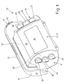
- the operating device 10 shown here is not used to operate in the figures illustrated tail lift at the rear of a vehicle, in particular a motor vehicle.
- the tail lift has in addition to the operating device 10 via a loading platform and a hoist, which the loading platform with a chassis of Vehicle connects.
- the tail lift is so the back of the vehicle assigned to the loading platform while driving the vehicle against the Rear of a structure, preferably a box body, the vehicle pivoted is.
- the hoist preferably has hydraulic cylinders that support the loading platform both pivot and raise and lower. If necessary, the Hubladebühne have more functions that from the control unit 10 to taxes are.
- the operating unit 10 is on one side of the vehicle, usually in states with Right-hand traffic, arranged at the rear under the Vehicle body.
- To operate the tail lift is an operator side next to the vehicle in front of a front side 17 of the operating device 10, wherein the Front 17 at the same time the operator side 11 is.
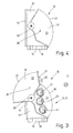
- Fig. 3 is symbolically through a circle with a cross, the operator 12 in front of the operating device 10 is shown.
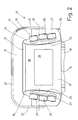
- the operating device 10 has a base part, which in the embodiment shown is formed as a closed box-like housing 13.
- In the housing 13th at least one cavity is arranged, in which not shown parts of operating organs, Terminals and connecting lines are housed the same. Possibly inside the housing 13 can also be a control or parts of the control of Be housed at the tail lift.
- the housing 13 has a flat rear side 14, a right angle extending, flat bottom 15, two opposite End faces 16 and in the present embodiment, curved front 17.
- An the bottom 15 is integrally formed on the housing 13 a flat, horizontal Screw base 18, whereby the operating device 10 to a corresponding traverse in particular the chassis of the vehicle is festschraubbar. It is also conceivable to associate the screw base 18 of the rear side 14 of the housing 13.
- the operating device 10 further has a housing associated with the cover 19 on.
- the cover 19 is in the manner of a helmet visor about an axis of rotation 20th pivotally mounted on the housing 13.
- the axis of rotation 20 lies on an imaginary, horizontal line that extends through the rear of the case and runs parallel to the horizontal longitudinal axis of the vehicle.
- the cover 19 has via a jacket surface 21 designed in the manner of a quarter-circle cylinder section and two opposite approximately quarter-circular end faces 22, which are integral to the Jacket surface 21 are formed.
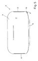
- the cover 19 is pivotable about a little over 90 ° from an open position shown in Figs. 1 to 3 in one of Figs. 4 and 5 shown closed position.
- the operating device 10 shown has two separate control panels.
- the control panels are assigned opposite end faces 16 of the housing 13. Thereby the panels are in different levels.
- operating device 10 are the panels as control surfaces 23 and 24th educated.
- the substantially flat control surfaces 23 and 24 are approximately the same size.
- the control surfaces 23 and 24 largely form the end faces 16 of the housing 13.
- Die Control surfaces 23 and 24 are characterized by opposite sides of the housing 13th accessible, making them in an ergonomic location for a two-handed operation are located.
- Each control surface 23 and 24 lies in a different plane. These are essentially vertical planes that are the longitudinal axis of the Vehicle transverse cuts.
- the Control surfaces 23 and 24 in both the vertical and horizontal direction easily inclined, in opposite directions.
- the control surfaces 23 and 24 are in the vertical direction so inclined in opposite directions that converge slightly converging towards the top. In the horizontal direction, the control surfaces 23 and 24 are also in opposite directions slightly inclined, in such a way that they converge towards the operator 12, So converge easily (Fig. 1 and 2). The control surfaces 23 and 24 but can also be inclined in one direction or have no inclination. In the last Traps are then the control surfaces in two parallel, vertical planes, which are the longitudinal axis vertical cut of the vehicle.
- the operating device 10 of FIGS. 1 to 3 has a total of six operating elements, the evenly distributed on the two control surfaces 23 and 24, so that both the Control surface 23 and the control surface 24 are each assigned to the controls.
- These controls are in the illustrated embodiment alike Rotary switches 25, 26 and 27 are formed.
- Opposite rotary switches 25, 26 and 27, respectively the left-hand control surface 23 and the right-hand control surface 24 each have the same Functions.
- the upper rotary switch 25 of the control surface 23 and 24 serve to pivot the loading platform of the tail lift. By the same directed turning of the rotary switch 25 in one direction becomes the loading platform swung open and swung in the other direction.
- the middle rotary switch 26 the control surface 23 and the control surface 24 can be used to raise and lower the Serve loading platform, wherein by rectified rotation of the rotary switch 26 after behind the loading platform is lowered and rectified by turning the Rotary switch 26 forward the loading platform can be raised.
- the same one in turn Function having lower rotary switch 27 of the control surfaces 23 and 24 can for Serve control of any special functions of the loading platform. It is also conceivable To control other functions hereby, for example, the extension and retraction of columns to secure the vehicle during loading and unloading.
- each control surface 23 and 24 a different number of rotary switches or Assign to other controls. It can be enough if each control surface 23, 24 only one control element or two control elements are assigned. It is also conceivable Assign more than three controls to each control surface 23 and 24.
- the three rotary switches 25 to 27 of each control surface 23, 24 are superimposed in a row arranged.
- the upper rotary switch 25 and the lower rotary switch 27 each control surface 23 and 24 are superimposed on an imaginary line, which is easy runs obliquely to the vertical, in such a way that the upper rotary switch 25 is slightly denser lies on the longitudinal center axis of the vehicle.
- the between the upper rotary switches 25th and lower rotary switches 27 arranged (middle) rotary switch 26 are slightly opposite the imaginary connecting line between each of a rotary switch 25 and 27th offset, in the embodiment shown to the rear, ie to the longitudinal center plane of the vehicle (Fig. 3). But it is also conceivable that the rotary switch 25, 26 and 27 have other relative arrangements to each other.
- the control surfaces 23 and 24 on the opposite end faces 16 of the housing 13 are spatially separated from each other by one on the front side 17 of the housing 13 located front wall portion 28.
- the operator 12 looks when they to operate the tail lift in front of the operating device 10 is on this front wall area 28.
- this front wall area 28 is user information, For example, textual instructions or pictograms for illustration the operation of the tail lift, provided.
- Figs. 1 and 2 only user information indicated in the outlines 29 instructions about the occupancy the functions of the rotary switches 25, 26 and 27.
- the user information 29 can at the production of the housing 13 made of plastic in the front wall portion 28 above or be formed deepened. But it is also conceivable, the user information 29 by to form a self-adhesive film subsequently applied to the front wall portion 28.
- the rotary switches 25, 26 and 27 directly or indirectly to illuminate.
- an indirect illumination of the rotary switches 25, 26 and 27, by the control surfaces 23 and 24 are illuminated.
- the lighting of the control surfaces 23 and 24 takes place in the embodiment shown in the manner of a backlight.
- 13 bulbs are arranged inside the housing, which lies in the housing 13 inside the control surfaces 23 and 24th spotlighting.
- the control surfaces 23 and 24 in the Rotary switches 25, 26 and 27 illuminates surrounding areas.
- the operating switches 25, 26 and 27 are then practically in front of an enlightened background, namely the disconnected one Control surfaces 23 and 24, arranged.
- the rotary switches 25, 26 and 27 and the user information 29 to illuminate the front wall portion 28 of the housing 13 indirectly, by at least that part of the front wall portion 28 of the housing 13 translucent is formed, over which the user information 29 extends.
- the User information 29 formed as depressions in the front wall portion 28 is only this deepening and thereby the text or the presentation of the user information 29 enlightened.
- the user information 29 is raised on the front wall area 28 attached, is mainly the raised user information 29th surrounding part of the front wall portion 28 be translucent.
- the user information formed by a sticker this is preferably a partially transparent sticker, in which either only the user information 29 with darker Color is printed or the user information 29 is transparent as such. Then Enlightens either the user information 29 or the environment of the same.
- the sight-like cover 19 is formed so as to be in the closed position ( Figures 4 and 5) the front of the housing 13, in particular all rotary switches 25, 26, 27, the control surfaces 23 and 24 and the front wall portion 28 hidden. at in the open position (Fig. 1 to 3) befindtsch cover 19 are the Control surfaces 23 and 24 and their associated rotary switches 25, 26 and 27 free accessible, as well as the front wall portion 28.
- the axis of rotation 20, whereby the Cover 19 pivotally hinged to the housing 13 is located specifically behind the Rotary switches 25, 26 and 27, and slightly above the middle rotary switch 26th (Fig. 3). This arrangement of the rotation axis 20 is deliberately made such that the Cover 19 in the fully open position (Fig. 3) remains without them must be arrested or locked. For this purpose, in Fig.
- Figs. 1 and 3 show at the front (right) end edge of the cover 19 a Tab 31 in which a transverse through-bore 32 is located.
- Through hole 32 corresponds to one in Fig. 2 suggestively recognizable Through hole 33.
- cover 19 In befind Anlagen in the closed position cover 19, ie when the operating device 10 is closed, the through holes 32 and 33 in the cover 19 or in the housing 13, whereby the operating device 10 at Non-use is lockable.
- At least the housing 13 and the cover 19 of the operating device 10 are made Plastic, preferably thermoplastic, formed. From the same Material can also be parts of the rotary switches 25, 26 and 27 are formed.
Landscapes
- Engineering & Computer Science (AREA)
- Transportation (AREA)
- Mechanical Engineering (AREA)
- Rotary Switch, Piano Key Switch, And Lever Switch (AREA)
- Valve Device For Special Equipments (AREA)
- Harvester Elements (AREA)
- Body Structure For Vehicles (AREA)
- Forklifts And Lifting Vehicles (AREA)
- Lighting Device Outwards From Vehicle And Optical Signal (AREA)
Applications Claiming Priority (2)
| Application Number | Priority Date | Filing Date | Title |
|---|---|---|---|
| DE20317896U | 2003-11-19 | ||
| DE20317896U DE20317896U1 (de) | 2003-11-19 | 2003-11-19 | Bedieneinrichtung für insbesondere eine Hubladebühne |
Publications (3)
| Publication Number | Publication Date |
|---|---|
| EP1533178A2 true EP1533178A2 (fr) | 2005-05-25 |
| EP1533178A3 EP1533178A3 (fr) | 2007-07-04 |
| EP1533178B1 EP1533178B1 (fr) | 2010-02-03 |
Family
ID=32087591
Family Applications (1)
| Application Number | Title | Priority Date | Filing Date |
|---|---|---|---|
| EP04025146A Expired - Lifetime EP1533178B1 (fr) | 2003-11-19 | 2004-10-22 | Dispositif de commande pour l' hayon élévateur |
Country Status (3)
| Country | Link |
|---|---|
| EP (1) | EP1533178B1 (fr) |
| AT (1) | ATE457004T1 (fr) |
| DE (2) | DE20317896U1 (fr) |
Citations (2)
| Publication number | Priority date | Publication date | Assignee | Title |
|---|---|---|---|---|
| EP0592795A1 (fr) | 1992-10-14 | 1994-04-20 | Abus Werner Bühne Kg. | Bouton-poussoir suspendu |
| EP1123835A1 (fr) | 2000-02-10 | 2001-08-16 | Sörensen Hydraulik Zweigniederlassung, Ulfborg, Filial af Sörensen Hydraulik GmbH, Tyskland | Unité de contrôle pour hayon élévateur |
Family Cites Families (6)
| Publication number | Priority date | Publication date | Assignee | Title |
|---|---|---|---|---|
| DE905310C (de) * | 1944-04-29 | 1954-03-01 | Siemens Ag | Bedienungsgeraet fuer Fernsteuerungen, insbesondere Kransteuerungen |
| DE3228798A1 (de) * | 1982-08-02 | 1984-02-02 | Emil Dautel GmbH, 7105 Leingarten | Bedien- und steuerelementekasten fuer elektrisch gesteuerte zusatzgeraete von lastfahrzeugen, insbesondere von hubladebuehnen |
| DE4446883A1 (de) * | 1994-12-27 | 1996-07-04 | Bosch Siemens Hausgeraete | Bedienblende für ein elektrisches Haushalt-Großgerät |
| DE19541791A1 (de) * | 1995-11-09 | 1997-05-15 | Mbb Foerder & Hebesysteme | Hubladebühne und Verfahren zur Steuerung derselben |
| DE29616262U1 (de) * | 1996-09-19 | 1997-10-16 | Siemens AG, 80333 München | Steuerpult mit Steuerdrehgriff für eine Vorrichtung mit mindestens einer aus- bzw. einfahrbaren Einheit, insbesondere dem Hebearm eines Hubwagens |
| DE10139735B4 (de) * | 2001-08-13 | 2004-12-16 | Scharfenberger, Kurt | Lastkraftwagen |
-
2003
- 2003-11-19 DE DE20317896U patent/DE20317896U1/de not_active Expired - Lifetime
-
2004
- 2004-10-22 DE DE502004010721T patent/DE502004010721D1/de not_active Expired - Lifetime
- 2004-10-22 AT AT04025146T patent/ATE457004T1/de active
- 2004-10-22 EP EP04025146A patent/EP1533178B1/fr not_active Expired - Lifetime
Patent Citations (2)
| Publication number | Priority date | Publication date | Assignee | Title |
|---|---|---|---|---|
| EP0592795A1 (fr) | 1992-10-14 | 1994-04-20 | Abus Werner Bühne Kg. | Bouton-poussoir suspendu |
| EP1123835A1 (fr) | 2000-02-10 | 2001-08-16 | Sörensen Hydraulik Zweigniederlassung, Ulfborg, Filial af Sörensen Hydraulik GmbH, Tyskland | Unité de contrôle pour hayon élévateur |
Also Published As
| Publication number | Publication date |
|---|---|
| EP1533178B1 (fr) | 2010-02-03 |
| DE20317896U1 (de) | 2004-04-01 |
| ATE457004T1 (de) | 2010-02-15 |
| DE502004010721D1 (de) | 2010-03-25 |
| EP1533178A3 (fr) | 2007-07-04 |
Similar Documents
| Publication | Publication Date | Title |
|---|---|---|
| DE3345122C2 (de) | Fahrzeugschiebedach | |
| DE19520348C1 (de) | Windabweiser | |
| DE20204110U1 (de) | Fahrzeug mit einer Dachanordnung; und eine solche Dachanordnung | |
| DE10151704A1 (de) | Deckelöffnungsmechanismus und Fahrzeugmittelkonsole | |
| DE102021200289A1 (de) | Verschiebbare heckklappe | |
| DE2920200A1 (de) | Verstaubare lichtanordnung fuer fahrzeuge | |
| DE19714105A1 (de) | Umwandelbares Fahrzeugdach | |
| DE102007039808A1 (de) | Kraftfahrzeug | |
| DE10239722B4 (de) | Höheneinstellvorrichtung für Schaltkästen an Fahrzeug-Fahrersitzen | |
| EP0627291B1 (fr) | Unité de commande pour une machine à mouler par injection | |
| DE2351270A1 (de) | Schwenkbarer deckel fuer fahrzeugdaecher | |
| DE4136045C2 (de) | Sicherheitsschranke | |
| DE19834850A1 (de) | Kraftfahrzeug mit versenkbarem Verdecksystem | |
| EP1533178B1 (fr) | Dispositif de commande pour l' hayon élévateur | |
| DE10039305A1 (de) | Führungsmechanismus für eine Abdeckplatte eines Ablagefachs in einem Fahrzeug | |
| DE3718125C1 (en) | Reversing viewing aid for cars | |
| DE69609016T2 (de) | Ein schwenkbarer Stossfänger für Kraftfahrzeuge, insbesondere für Personenkraftwagen | |
| EP1197367A2 (fr) | Porte de cabine d' un véhicule avec un évidement dans la partie inférieure et/ou avec la partie inférieure pivotable vers le haut | |
| DE2316071C3 (de) | Haltevorrichtung für zahnärztliche Handstücke | |
| EP1184220B1 (fr) | Chariot de manutention | |
| EP0398275A2 (fr) | Pare-soleil pour véhicules automobiles | |
| EP1354826A1 (fr) | Armoire à poubelle | |
| DE102019216209B4 (de) | Tür oder Klappe eines Fahrzeugs mit einer Handhabe sowie Fahrzeug | |
| EP3564071B1 (fr) | Dispositif de commande pour une plateforme de chargement par levage | |
| DE10341034A1 (de) | Pantographtür oder-klappe |
Legal Events
| Date | Code | Title | Description |
|---|---|---|---|
| PUAI | Public reference made under article 153(3) epc to a published international application that has entered the european phase |
Free format text: ORIGINAL CODE: 0009012 |
|
| AK | Designated contracting states |
Kind code of ref document: A2 Designated state(s): AT BE BG CH CY CZ DE DK EE ES FI FR GB GR HU IE IT LI LU MC NL PL PT RO SE SI SK TR |
|
| AX | Request for extension of the european patent |
Extension state: AL HR LT LV MK |
|
| PUAL | Search report despatched |
Free format text: ORIGINAL CODE: 0009013 |
|
| AK | Designated contracting states |
Kind code of ref document: A3 Designated state(s): AT BE BG CH CY CZ DE DK EE ES FI FR GB GR HU IE IT LI LU MC NL PL PT RO SE SI SK TR |
|
| AX | Request for extension of the european patent |
Extension state: AL HR LT LV MK |
|
| 17P | Request for examination filed |
Effective date: 20070711 |
|
| 17Q | First examination report despatched |
Effective date: 20070907 |
|
| AKX | Designation fees paid |
Designated state(s): AT BE BG CH CY CZ DE DK EE ES FI FR GB GR HU IE IT LI LU MC NL PL PT RO SE SI SK TR |
|
| RAP1 | Party data changed (applicant data changed or rights of an application transferred) |
Owner name: MBB PALFINGER GMBH |
|
| GRAP | Despatch of communication of intention to grant a patent |
Free format text: ORIGINAL CODE: EPIDOSNIGR1 |
|
| GRAS | Grant fee paid |
Free format text: ORIGINAL CODE: EPIDOSNIGR3 |
|
| GRAA | (expected) grant |
Free format text: ORIGINAL CODE: 0009210 |
|
| AK | Designated contracting states |
Kind code of ref document: B1 Designated state(s): AT BE BG CH CY CZ DE DK EE ES FI FR GB GR HU IE IT LI LU MC NL PL PT RO SE SI SK TR |
|
| REG | Reference to a national code |
Ref country code: GB Ref legal event code: FG4D Free format text: NOT ENGLISH |
|
| REG | Reference to a national code |
Ref country code: CH Ref legal event code: EP |
|
| REG | Reference to a national code |
Ref country code: IE Ref legal event code: FG4D |
|
| REF | Corresponds to: |
Ref document number: 502004010721 Country of ref document: DE Date of ref document: 20100325 Kind code of ref document: P |
|
| REG | Reference to a national code |
Ref country code: NL Ref legal event code: VDEP Effective date: 20100203 |
|
| PG25 | Lapsed in a contracting state [announced via postgrant information from national office to epo] |
Ref country code: ES Free format text: LAPSE BECAUSE OF FAILURE TO SUBMIT A TRANSLATION OF THE DESCRIPTION OR TO PAY THE FEE WITHIN THE PRESCRIBED TIME-LIMIT Effective date: 20100514 Ref country code: PT Free format text: LAPSE BECAUSE OF FAILURE TO SUBMIT A TRANSLATION OF THE DESCRIPTION OR TO PAY THE FEE WITHIN THE PRESCRIBED TIME-LIMIT Effective date: 20100603 |
|
| PG25 | Lapsed in a contracting state [announced via postgrant information from national office to epo] |
Ref country code: PL Free format text: LAPSE BECAUSE OF FAILURE TO SUBMIT A TRANSLATION OF THE DESCRIPTION OR TO PAY THE FEE WITHIN THE PRESCRIBED TIME-LIMIT Effective date: 20100203 Ref country code: FI Free format text: LAPSE BECAUSE OF FAILURE TO SUBMIT A TRANSLATION OF THE DESCRIPTION OR TO PAY THE FEE WITHIN THE PRESCRIBED TIME-LIMIT Effective date: 20100203 Ref country code: SI Free format text: LAPSE BECAUSE OF FAILURE TO SUBMIT A TRANSLATION OF THE DESCRIPTION OR TO PAY THE FEE WITHIN THE PRESCRIBED TIME-LIMIT Effective date: 20100203 |
|
| REG | Reference to a national code |
Ref country code: IE Ref legal event code: FD4D |
|
| PG25 | Lapsed in a contracting state [announced via postgrant information from national office to epo] |
Ref country code: RO Free format text: LAPSE BECAUSE OF FAILURE TO SUBMIT A TRANSLATION OF THE DESCRIPTION OR TO PAY THE FEE WITHIN THE PRESCRIBED TIME-LIMIT Effective date: 20100203 Ref country code: GR Free format text: LAPSE BECAUSE OF FAILURE TO SUBMIT A TRANSLATION OF THE DESCRIPTION OR TO PAY THE FEE WITHIN THE PRESCRIBED TIME-LIMIT Effective date: 20100504 Ref country code: CY Free format text: LAPSE BECAUSE OF FAILURE TO SUBMIT A TRANSLATION OF THE DESCRIPTION OR TO PAY THE FEE WITHIN THE PRESCRIBED TIME-LIMIT Effective date: 20100203 Ref country code: EE Free format text: LAPSE BECAUSE OF FAILURE TO SUBMIT A TRANSLATION OF THE DESCRIPTION OR TO PAY THE FEE WITHIN THE PRESCRIBED TIME-LIMIT Effective date: 20100203 Ref country code: SE Free format text: LAPSE BECAUSE OF FAILURE TO SUBMIT A TRANSLATION OF THE DESCRIPTION OR TO PAY THE FEE WITHIN THE PRESCRIBED TIME-LIMIT Effective date: 20100203 Ref country code: IE Free format text: LAPSE BECAUSE OF FAILURE TO SUBMIT A TRANSLATION OF THE DESCRIPTION OR TO PAY THE FEE WITHIN THE PRESCRIBED TIME-LIMIT Effective date: 20100203 Ref country code: NL Free format text: LAPSE BECAUSE OF FAILURE TO SUBMIT A TRANSLATION OF THE DESCRIPTION OR TO PAY THE FEE WITHIN THE PRESCRIBED TIME-LIMIT Effective date: 20100203 |
|
| PG25 | Lapsed in a contracting state [announced via postgrant information from national office to epo] |
Ref country code: CZ Free format text: LAPSE BECAUSE OF FAILURE TO SUBMIT A TRANSLATION OF THE DESCRIPTION OR TO PAY THE FEE WITHIN THE PRESCRIBED TIME-LIMIT Effective date: 20100203 Ref country code: SK Free format text: LAPSE BECAUSE OF FAILURE TO SUBMIT A TRANSLATION OF THE DESCRIPTION OR TO PAY THE FEE WITHIN THE PRESCRIBED TIME-LIMIT Effective date: 20100203 Ref country code: BG Free format text: LAPSE BECAUSE OF FAILURE TO SUBMIT A TRANSLATION OF THE DESCRIPTION OR TO PAY THE FEE WITHIN THE PRESCRIBED TIME-LIMIT Effective date: 20100503 |
|
| PLBE | No opposition filed within time limit |
Free format text: ORIGINAL CODE: 0009261 |
|
| STAA | Information on the status of an ep patent application or granted ep patent |
Free format text: STATUS: NO OPPOSITION FILED WITHIN TIME LIMIT |
|
| 26N | No opposition filed |
Effective date: 20101104 |
|
| PG25 | Lapsed in a contracting state [announced via postgrant information from national office to epo] |
Ref country code: DK Free format text: LAPSE BECAUSE OF FAILURE TO SUBMIT A TRANSLATION OF THE DESCRIPTION OR TO PAY THE FEE WITHIN THE PRESCRIBED TIME-LIMIT Effective date: 20100203 |
|
| PG25 | Lapsed in a contracting state [announced via postgrant information from national office to epo] |
Ref country code: IT Free format text: LAPSE BECAUSE OF FAILURE TO SUBMIT A TRANSLATION OF THE DESCRIPTION OR TO PAY THE FEE WITHIN THE PRESCRIBED TIME-LIMIT Effective date: 20100203 |
|
| BERE | Be: lapsed |
Owner name: MBB PALFINGER G.M.B.H. Effective date: 20101031 |
|
| PG25 | Lapsed in a contracting state [announced via postgrant information from national office to epo] |
Ref country code: MC Free format text: LAPSE BECAUSE OF NON-PAYMENT OF DUE FEES Effective date: 20101031 |
|
| REG | Reference to a national code |
Ref country code: CH Ref legal event code: PL |
|
| PG25 | Lapsed in a contracting state [announced via postgrant information from national office to epo] |
Ref country code: LI Free format text: LAPSE BECAUSE OF NON-PAYMENT OF DUE FEES Effective date: 20101031 Ref country code: CH Free format text: LAPSE BECAUSE OF NON-PAYMENT OF DUE FEES Effective date: 20101031 |
|
| PG25 | Lapsed in a contracting state [announced via postgrant information from national office to epo] |
Ref country code: BE Free format text: LAPSE BECAUSE OF NON-PAYMENT OF DUE FEES Effective date: 20101031 |
|
| PG25 | Lapsed in a contracting state [announced via postgrant information from national office to epo] |
Ref country code: LU Free format text: LAPSE BECAUSE OF NON-PAYMENT OF DUE FEES Effective date: 20101022 Ref country code: HU Free format text: LAPSE BECAUSE OF FAILURE TO SUBMIT A TRANSLATION OF THE DESCRIPTION OR TO PAY THE FEE WITHIN THE PRESCRIBED TIME-LIMIT Effective date: 20100804 |
|
| PG25 | Lapsed in a contracting state [announced via postgrant information from national office to epo] |
Ref country code: TR Free format text: LAPSE BECAUSE OF FAILURE TO SUBMIT A TRANSLATION OF THE DESCRIPTION OR TO PAY THE FEE WITHIN THE PRESCRIBED TIME-LIMIT Effective date: 20100203 |
|
| PGFP | Annual fee paid to national office [announced via postgrant information from national office to epo] |
Ref country code: AT Payment date: 20131028 Year of fee payment: 10 |
|
| REG | Reference to a national code |
Ref country code: AT Ref legal event code: MM01 Ref document number: 457004 Country of ref document: AT Kind code of ref document: T Effective date: 20141022 |
|
| PG25 | Lapsed in a contracting state [announced via postgrant information from national office to epo] |
Ref country code: AT Free format text: LAPSE BECAUSE OF NON-PAYMENT OF DUE FEES Effective date: 20141022 |
|
| REG | Reference to a national code |
Ref country code: FR Ref legal event code: PLFP Year of fee payment: 12 |
|
| REG | Reference to a national code |
Ref country code: FR Ref legal event code: PLFP Year of fee payment: 13 |
|
| REG | Reference to a national code |
Ref country code: DE Ref legal event code: R082 Ref document number: 502004010721 Country of ref document: DE Representative=s name: MEISSNER BOLTE PATENTANWAELTE RECHTSANWAELTE P, DE Ref country code: DE Ref legal event code: R081 Ref document number: 502004010721 Country of ref document: DE Owner name: PALFINGER TAIL LIFTS GMBH, DE Free format text: FORMER OWNER: MBB PALFINGER GMBH, 27777 GANDERKESEE, DE |
|
| REG | Reference to a national code |
Ref country code: FR Ref legal event code: PLFP Year of fee payment: 14 |
|
| REG | Reference to a national code |
Ref country code: FR Ref legal event code: PLFP Year of fee payment: 15 |
|
| PGFP | Annual fee paid to national office [announced via postgrant information from national office to epo] |
Ref country code: GB Payment date: 20210930 Year of fee payment: 18 |
|
| PGFP | Annual fee paid to national office [announced via postgrant information from national office to epo] |
Ref country code: DE Payment date: 20210929 Year of fee payment: 18 |
|
| PGFP | Annual fee paid to national office [announced via postgrant information from national office to epo] |
Ref country code: FR Payment date: 20211018 Year of fee payment: 18 |
|
| REG | Reference to a national code |
Ref country code: DE Ref legal event code: R119 Ref document number: 502004010721 Country of ref document: DE |
|
| GBPC | Gb: european patent ceased through non-payment of renewal fee |
Effective date: 20221022 |
|
| PG25 | Lapsed in a contracting state [announced via postgrant information from national office to epo] |
Ref country code: FR Free format text: LAPSE BECAUSE OF NON-PAYMENT OF DUE FEES Effective date: 20221031 Ref country code: DE Free format text: LAPSE BECAUSE OF NON-PAYMENT OF DUE FEES Effective date: 20230503 |
|
| PG25 | Lapsed in a contracting state [announced via postgrant information from national office to epo] |
Ref country code: GB Free format text: LAPSE BECAUSE OF NON-PAYMENT OF DUE FEES Effective date: 20221022 |