EP1533471A1 - Boulon d'ancrage déformable - Google Patents
Boulon d'ancrage déformable Download PDFInfo
- Publication number
- EP1533471A1 EP1533471A1 EP04104841A EP04104841A EP1533471A1 EP 1533471 A1 EP1533471 A1 EP 1533471A1 EP 04104841 A EP04104841 A EP 04104841A EP 04104841 A EP04104841 A EP 04104841A EP 1533471 A1 EP1533471 A1 EP 1533471A1
- Authority
- EP
- European Patent Office
- Prior art keywords
- anchor
- sliding
- engagement
- external thread
- rod
- Prior art date
- Legal status (The legal status is an assumption and is not a legal conclusion. Google has not performed a legal analysis and makes no representation as to the accuracy of the status listed.)
- Granted
Links
- 239000011435 rock Substances 0.000 title description 2
- 238000005553 drilling Methods 0.000 claims abstract description 9
- 239000000463 material Substances 0.000 claims description 24
- 229910000831 Steel Inorganic materials 0.000 claims description 19
- 239000010959 steel Substances 0.000 claims description 19
- 238000006073 displacement reaction Methods 0.000 claims description 16
- 239000002131 composite material Substances 0.000 claims description 13
- 238000005520 cutting process Methods 0.000 claims description 12
- 239000004568 cement Substances 0.000 claims description 7
- 239000000853 adhesive Substances 0.000 claims description 3
- 230000001070 adhesive effect Effects 0.000 claims description 3
- 238000010008 shearing Methods 0.000 claims description 2
- 238000002347 injection Methods 0.000 abstract description 8
- 239000007924 injection Substances 0.000 abstract description 8
- 238000004873 anchoring Methods 0.000 description 10
- 230000008901 benefit Effects 0.000 description 8
- 239000004567 concrete Substances 0.000 description 8
- 230000008878 coupling Effects 0.000 description 8
- 238000010168 coupling process Methods 0.000 description 8
- 238000005859 coupling reaction Methods 0.000 description 8
- 238000003825 pressing Methods 0.000 description 5
- 238000004519 manufacturing process Methods 0.000 description 3
- 239000008267 milk Substances 0.000 description 3
- 210000004080 milk Anatomy 0.000 description 3
- 235000013336 milk Nutrition 0.000 description 3
- 230000009471 action Effects 0.000 description 2
- 230000006978 adaptation Effects 0.000 description 2
- 238000010276 construction Methods 0.000 description 2
- 230000000881 depressing effect Effects 0.000 description 2
- 239000012530 fluid Substances 0.000 description 2
- 239000011440 grout Substances 0.000 description 2
- 239000007787 solid Substances 0.000 description 2
- 230000007704 transition Effects 0.000 description 2
- 230000002411 adverse Effects 0.000 description 1
- 150000001875 compounds Chemical class 0.000 description 1
- 238000002788 crimping Methods 0.000 description 1
- 230000000694 effects Effects 0.000 description 1
- 230000005489 elastic deformation Effects 0.000 description 1
- 238000003780 insertion Methods 0.000 description 1
- 230000037431 insertion Effects 0.000 description 1
- 230000003993 interaction Effects 0.000 description 1
- 238000003754 machining Methods 0.000 description 1
- 239000004570 mortar (masonry) Substances 0.000 description 1
- 230000000149 penetrating effect Effects 0.000 description 1
- 230000003716 rejuvenation Effects 0.000 description 1
- 230000035939 shock Effects 0.000 description 1
- 239000002002 slurry Substances 0.000 description 1
- 125000006850 spacer group Chemical group 0.000 description 1
- 239000004575 stone Substances 0.000 description 1
- 229910000859 α-Fe Inorganic materials 0.000 description 1
Images



Classifications
-
- E—FIXED CONSTRUCTIONS
- E21—EARTH OR ROCK DRILLING; MINING
- E21D—SHAFTS; TUNNELS; GALLERIES; LARGE UNDERGROUND CHAMBERS
- E21D21/00—Anchoring-bolts for roof, floor in galleries or longwall working, or shaft-lining protection
- E21D21/008—Anchoring or tensioning means
Definitions
- the present invention relates to a sliding anchor, in particular self-drilling Gleitinjedgingsanker, comprising at least one with external thread provided anchor rod and at least one Gleitankerkopf along the Anchor rod is displaceable overcoming a sliding resistance.
- Such sliding anchors are used in the construction of cavities in particular depressing mountains. It may be the removal of rock loads around the cavity, depending on the mechanical properties of the subsoil due to stress redistributions to excess strength come with, i. d. R. comparatively far in subsoil-related shifts.
- cavity protection by means of compliant shoring can accordingly sliding linings of the cavity with said Sliding anchors are anchored, with a tearing of the sliding anchor head by its displaceability in overcoming a limit load along the first is avoided in the cavity projecting anchor head bar.
- a sliding anchor of the type mentioned is known from DE 3507089 A1.
- the sliding resistance i. the limit load of the sliding anchor
- the slide anchor head is slidable on the anchor rod, through a multi-stage Cutting the external thread of the anchor rod by the Gleitankerkopf generated.
- the required cutting edges are on separate cutting segments provided, which is conical for mounting the Gleitankerkopfes whose housing can be pressed in. This means that after positioning the Gleitankerkopfes still to achieve the required sliding resistance with the pressing of the cutting segments on the site another step necessary is.
- the Cutting edges formed directly in the housing of Gleitankerkopfes but no (pre-) setting a desired sliding resistance is possible.
- the known variants have in common that on the one hand comparatively complicated production of Gleitankerkopfes also the There is a risk that the cutting, i. also the sliding resistance, by a Tilting of the anchor head and wear of the cutting edges adversely affected.
- the object of the present invention is to provide a sliding anchor of the type mentioned production and technical use to develop advantageous.
- pin-like stands for design forms, which allow threaded engagement at the thread periphery, such as pins with round or polygonal cross-section, with further possible conical, rounded or continuous cross-section pin end. Also conceivable would be, for example, a ball or the like, in the Gleitankerkopf is suitably held for engagement in the external thread.
- inventive Compliance can in principle on the one hand on the part of the engagement element exist that, for example, resiliently against the thread ribs of the external thread the anchor rod can be employed. On the other hand, under the Invention preferred that the said compliance on the part of the external thread the anchor rod is provided. There is the possibility that the engagement element when exceeding the certain sliding resistance of the Sliding anchor head, i.
- a displacement of the external thread e-rib causes.
- the displacement is preferably achieved in that a Engaging element with respect to the external thread higher skill or Has hardness and overcoming the predetermined sliding resistance by reaching the ultimate load of the sliding anchor for plowing or shear through the male thread rib in anchor longitudinal direction through the engagement profile comes.
- the sliding anchor head in a variety of ways to a certain desired sliding resistance on the anchor rod customizable is, in particular in the form that the sliding resistance variably adjustable is.
- the Range such as low, medium or high limit load
- an appropriate Number of engagement elements on the slide anchor head for engagement in the external thread is arranged.
- the sliding resistance consists of the displacement resistance of the multiple engagement elements together.
- the depth of engagement the or an engagement element in the external thread adjustable, in particular continuously adjustable is.
- the engagement element in the slider anchor an assigning to the anchor rod Pass through hole and held longitudinally adjustable by adjusting thread and preferably be lockable with a lock nut.
- the depth of engagement of the Engagement element in the external thread about the same or slightly smaller than the Thread depth of the external thread is. This ensures that by the displacement effect the engagement element in the longitudinal direction in the anchor rod no continuous groove is created, so the risk of material jams and undesirably increasing sliding resistance is avoided. Also, if the depth of engagement is about the same or slightly smaller than the thread depth safer, less sensitive to manufacturing tolerances and tilting Intervention achieved.
- a setting of the sliding resistance is finally in the Ways of suitable adaptation of the profile width of the engagement element, i. For example, the cross-sectional diameter, possible.
- An expedient design of the sliding anchor can according to the invention also are that in Gleitankerl horrscardi the thread rib distance of External thread with a corresponding cross-sectional position greater than the extension of the engagement element, wherein the thread rib spacing is preferred about two to three times the extension of the engagement element in the longitudinal direction can amount.
- this makes the recording room in proportion increased to the repressed material, on the other can be at give the advantage over the sliding anchor uniform external thread advantage that the shear strength of a mortar of the anchor is improved.
- the sliding anchor head at least two engagement elements having, with respect to the external thread of the anchor rod in each other Unequal phase position are kept, so that in Gleitankerlteilscardi a Overall virtually play-free engagement of the sliding anchor head in the external thread the anchor rod is obtained.
- two engagement elements which have at their engagement end cone tips, so on the Gleitankerkopf be held that the apex of the first engagement element on the a (for example, left) thread flank of the external thread and the cone tip the second engagement element on the respect. Of the thread curve other (i.e., then, for example, right) thread flank abuts.
- a plurality of engagement elements can the profile cross section and the distance between the External thread rib (s) and the number, phase and engagement profile of Engagement elements be tuned so that at any time at least one of the engagement elements in loading direction in plant or displacement position is located to the external thread rib, so that the sliding resistance along the Gleitweges is consistently effective.
- This can be useful provided be that the thread rib of the external thread has a substantially trapezoidal Cross-section, wherein the lateral trapezoidal flanks in particular turn rounded into the thread root.
- the foot of the Trapezoidal flanks can thus depending on the shape of the engagement end of the engagement elements be included in the thread profile to be displaced, wherein, based on an engagement element between two displacement profiles a displacement-free space remains.
- a vote also possible in the way that over the entire Gleitweg a same or at least approximately the same sliding resistance is effective.
- two pairs of each provided two mutually circumferentially engaging elements are whose pairs connecting lines of the engaging elements each other in Cut the projection vertically, and that the engaging elements of each one same pair to each other in phase and each different pairs to Achieving a play-free threaded engagement in phase with respect to the External thread are arranged.
- four each by a quarter turn on the circumference and in pairs about half the thread pitch be present in the axial direction of the pipe anchor offset elements which can be adjusted with a thread gauge so that the engaging ends, For example, cone tips, each on opposite thread flanks issue.
- the sliding nut can thus, for example, to a maximum load in GleitankerlCode in the range of 50 to 100 kN, preferably one maximum load of 70 kN, to be set over the gliding path remains about the same, so that when sliding no jerky compliances or shocks occur.
- the engagement element or its engagement end eg. Cone tip
- the glide path be limited by the fact that an end stop, for example by a On this screwed ball nut, is provided.
- the convergences of the mountains become well visible through the glide path (furrows).
- An excess Anchor overhang, which does not disappear in the mountain, can later be separated become.
- the sliding anchor in addition to the aforementioned Anchor rod still a number of other anchor rods with corresponding and over the length of passing external thread comprises, so that all anchor rods by means of coupling nuts with matching internal thread are connectable. This brings the advantage that the sliding anchor in Shots that can be connected through the coupling nuts, even in confined spaces Space, in the mountains can be introduced.
- the present invention further relates to a sliding anchor, in particular self-drilling slip injection anchor comprising at least one anchor foot bar section, in particular at least one first anchor rod, and at least an anchor head bar section, in particular at least one further Anchor rod, and at least one Gleitankerkopf which along the anchor rod section overcoming a sliding resistance in Gleitankerlteilsraum is displaceable.
- a sliding anchor in particular self-drilling slip injection anchor comprising at least one anchor foot bar section, in particular at least one first anchor rod, and at least an anchor head bar section, in particular at least one further Anchor rod, and at least one Gleitankerkopf which along the anchor rod section overcoming a sliding resistance in Gleitankerlnature is displaceable.
- the problem is especially in the case of rocky mountains given that in yielding shoring in the longitudinal direction of the anchor running shifts in the ground to a high tensile load of Anchor.
- the anchoring section provides the longitudinal section of the anchor, in which, for example, injection with injection fluid (e.g. Cement milk) or sticking in the borehole.
- injection fluid e.g. Cement milk
- the anchor head bar section is the longitudinal opposite, i. the borehole mouth associated anchor section.
- the anchor foot bar section and The anchor head rod section can basically either at one common, i. continuous anchor rod or, as in the present Invention preferred, provided on various anchor rods be. The latter can in turn either adjacent or under interposition Further anchor rods, for example, connected to each other by coupling elements be.
- the anchor foot material may be around the so-called yield strength or act around the lower yield strength.
- the material elastic limit of the Ankerfußstangenabiteses two to five times, more preferably about 2.5 times that in the Ankerfußstangenabites maximum resulting voltage is. This means that with preloaded anchor also additional shifts of the Underground at the Ankerfußstangenabites initially only a small cause elastic strain, which advantageously also the risk of damage of the shear bond through the grout or cement stone is reduced.
- This overload protection is particularly important for a possible biasing of the sliding anchor by means of the sliding anchor head already shortly after one for anchoring the sliding anchor in the anchor hole used shear composite medium, for example on a cement or adhesive basis, has been introduced into the anchor hole. It is preferred that the resulting from the particular sliding resistance of the Gleitankerkopfes Shear stress between anchor rod section and shear composite medium less than the shear strength between anchor foot bar section and finally cured shear composite medium, in particular that these 20 to 80%, more particularly about 50%, of said shear strength is.
- the anchor rod in the region of Ankerfußstangenabiteses is made of a material whose yield ratio (i.e. the ratio of yield point to ultimate load) in the range between 0.5 and 0.7, in particular about 0.6.
- an anchor rod provided at anchor foot only at a assumed anchor tensile stress of about 175 kN the 0.2% proof stress while the breaking load with an anchor force of approx. 300 kN and 13.5% elongation is still significantly higher.
- the sliding resistance of the Gleitankerkopfes along the anchor rod in the region of the anchor rod section can thereby preferably to a maximum load in the longitudinal direction be adapted from 70 kN.
- a material for the Ankerfußstangenabites as well as in particular for other anchor sections is in particular a heat-treated austenitic steel with a high plastic stretchability or austenitic-ferritic steel, in particular a so-called duplex steel with the international material no.
- the anchor head is advantageous if this also has an external thread and a Gleitankerkopf with at least one pin-like, to an engagement in the external thread adapted for screwing the Gleitankerkopfes on the anchor rod Engagement element is provided, wherein the intervention when exceeding a certain Sliding resistance to achieve a displaceable yielding is. Also the others, already leading to such a sliding anchor head described features can be realized individually or in combination be.
- an embodiment of the sliding anchor can offer advantages in which between a crimping section or anchor foot section and an anchor head section a free play section is provided, which is a substantially smooth one Having outer surface.
- a free play section is provided, which is a substantially smooth one Having outer surface.
- An expedient development of the sliding anchor is also possible because of the anchor foot bar section, the anchor head bar section and in particular the free play section on separate Anchor rods are provided, which is a similar, over the length have continuous external thread and by means of coupling nuts with Matching internal thread can be connected.
- Suitable are, for example, round threads, Trapezoidal thread or the like, preferably on the rod outside rolled up.
- the thread ribs may have a groove at the apex, as described for example in DE 3400182 A1.
- a corresponding modular sliding anchor can be in shots connected by coupling nuts are used even in confined spaces.
- the anchor rod outer thread to the Achieving a smooth outer surface of a jacket, in particular is encased in a PVC hose.
- the PVC hose can do this first For example, expanded with compressed air, in corresponding lengths pushed onto the anchor rods and then shrunk by switching off the pressure whereupon the putting into the underground in shots he follows.
- the anchor rods in the longitudinal direction continuously respectively a closed hollow cross-section with, for example, circular or polygonal Own form.
- a known injection means or Shear composite medium such as cement slurry
- the slip anchor preferably to a drill bit attached to the anchor tip and through openings in it from the wellbore deepest in the annular gap around the Sliding anchors are pressed.
- anchor rods are used with a solid cross-section, the sliding anchor then by means of separately introduced into the well Adhesive can be anchored.
- Fig. 1 shows in a sectional longitudinal view of a preferred embodiment the sliding anchor according to the invention, which in a surrounded by mountains 2 Drill hole 3 is already anchored.
- the example chosen is in the sliding anchor 1 to a self-drilling Gleitinjemiesanker, the as a system anchor in several shots of one to be secured, not closer shown cavity starting through a concrete wall 4 through the mountains 2 was introduced.
- the sliding anchor 1 has, the well deepest 5, a drill bit 6, which initially with an internal thread on a cut anchor rod 7 shown with matching external thread is screwed on.
- the anchor rod 7 has a center in the longitudinal direction through cavity 8, which in the drill bit 6 in conjunction with another cavity is located, leading to several at the periphery of the drill bit 6 distributed, not shown outlet openings branched out.
- At the aforementioned anchor rod 7 close in armature longitudinal direction yet further, in the selected example geometrically corresponding anchor rods. 7 at.
- adjacent anchor rods 7 are each through a Coupling nut 10 connected to the external thread of the anchor rods 7 matching internal thread screwed on the respective ends are.
- the overall length of the sliding anchor 1 achieved in this way is dimensioned so that this with a free end 11 of a terminating anchor rod 7 on the concrete wall 4 in the cavity to be secured, for example. Tunnel, survives.
- the free End 11 is broken in Fig. 1 to indicate that the free end can also have a different length as needed.
- the anchor rods 7, with the drill bit 6 in a conventional manner as a self-drilling injection anchor are to be introduced into the mountains 2, thus forming a central continuous Feed channel, through which from the free end 11 and the drive side starting a shear composite medium 12 over the wellbore 5 deepest in the borehole 3 can be pressed.
- the pressing of the shear composite medium 12 can be done with continuous armature rotation, thereby anchoring a shear bond between Gleitanker, in particular the external thread of the Anchor rods, and shear composite medium on the one hand and Scherverbundmedium and mountains on the other hand.
- Pressing body 13 can in the Scherverbundmedium, such as. Cement milk, also solid, such as cuttings or the like, embedded be.
- the achievable for the shear composite medium 12 annulus in the borehole 3 is in anchor longitudinal direction in the example chosen limited by a per se also known well closure 15, which at the height of the mountains 2 facing edge region of the concrete wall 4 is arranged.
- Gleitankerkopf Screwed 16 To brace the concrete wall 4 against the mountains 2 can, is on the anchor rod 7 in the region of the free end 11 a Gleitankerkopf Screwed 16 according to the present invention, so that this against a supported on the concrete wall 4 dome plate 17 presses.
- Gleitankerkopf 16 also has the property that he under overcoming a certain preset sliding resistance of his on the Anchor rod 7 screwed position starting in GleitankerlNicolscardi L is displaceable, with reference to the underlying mode of action below will be discussed separately.
- a longitudinal displacement of the sliding anchor head 16 by pushing the mountains 2 is only by an end stop 18 limited in the example as a screwed onto the anchor rod 7 Ball nut is formed.
- Anchor rods 7 may have different lengths, or that in the various Sections basically a different number of anchor rods 7 is possible.
- Anchor footstep section, free play section and Anchor rod section can, as in the example chosen, from a each integer number of anchor rod 7 consist.
- On the other hand are but also overlaps and possibly even across all sections continuous anchor rod conceivable.
- individual anchor rods 7 a length of, for example. 2 meters appropriate.
- Ankerfußstangenabterrorism as anchoring a length of For example, 2 meters, 4 meters, preferably 6 meters, etc. reach.
- the sliding anchor head 16 is so on the anchor head rod portion K forming anchor rod 7 tuned that he off reaching or exceeding a compressive force of the concrete wall 4 against the Dome plate 17 or sliding sleeve of 70 kN while maintaining the sliding resistance on the anchor rod 7 in the direction of the end stop 18 longitudinally displaceable is.
- the anchor rod (s) of the Ankerfußstangenabiteses F the made of duplex steel material no. 1.4462, experienced at one of the anchor rod 7 of the anchor rod section K corresponding cross-section even with an anchor force of about 175 kN, i. about 2.5 times the Selective sliding resistance, an elastic strain of less than 1%, the below the material elastic limit of the duplex steel used.
- Gleitankerkopf 16 biasing the sliding anchor 1 by means Gleitankerkopf 16 is the Anchor force limited by the specific sliding resistance to a maximum of 70 kN.
- the strain resulting in the anchor foot bar section F becomes limited by this overload protection to such a low level that the danger Damage to the shear bond between anchor rod 7 and Pressing body 13 is largely reduced.
- the Sliding anchor 1 After tightening the Sliding anchor 1 performs a sliding of the mountain 2 against the concrete wall 4 first in addition, that due to higher tie-pull load and exceeding the sliding resistance the sliding anchor head 16 in still maintained sliding resistance towards the end stop 18 slides until the sliding action by support is terminated. With further pushing of the mountains the anchor force increases.
- Breakage protection initially up to at least 2.5 times the Ankervorspannkraft an elastic stretching behavior of the anchor rods made of duplex steel to disposal. Due to the low yield ratio of duplex steel can be an even more increasing in the chosen example Stress due to a subsequent plastic deformation still up to a breaking load of about 4 times that of the sliding anchor head 16 chosen sliding resistance are endured.
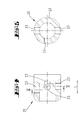
- FIG. 2 shows the sliding anchor head 16 of the sliding anchor 1 shown in FIG a contrast enlarged sectional view taken along section line II-II, wherein the dome plate 17 is not shown.
- FIG. 3 shows a to Fig. 2 vertical sectional view taken along section line III-III in Fig. 2.
- the Sliding anchor head 16 has a sleeve 20 with through hole 21. These has a substantially smooth inner wall and is in diameter to Enabling a displacement in the longitudinal direction L slightly larger as the external thread 22 of the anchor rod 7 dimensioned.
- the sleeve 20 has in their wall on the circumference offset by a quarter turn each other lying threaded holes 23, in which in each case an engagement element 24, in the example chosen a hardened stud, screwed in radially is.
- the engagement elements 24 have, facing the anchor rod 7, depending on a cone tip 25 with flattened end, which is when screwing in the threaded holes 23 in engagement with the external thread 22 of the anchor rod 7 bring.
- an engagement depth which is approximately equal to the thread depth of the external thread 7, so that the flattened end of the conical tips 25th the thread base 26 of the external thread 7 just not or hardly noticeable touched.
- Engagement end of the engagement elements 24 By rejuvenating to its free end Engagement end of the engagement elements 24 is the possibility of the engagement depth to be set so that in the longitudinal direction L a virtually straight clearance setting is obtained, which at the same time a screwing the Gleitankerkopfes 16th allowed on the anchor rod 7.
- a hemispherical engagement end could also be provided for this purpose.
- the profile of the engagement end can in particular also be designed so that the previously described backlash-free and suitable for screwing engagement automatically results when the engagement elements until just a slight Touching the thread root 26, i. up to a just noticeable increase be screwed in the torque.
- the described sliding anchor head 16 can be pre-assembled on the anchor rod 7 on the one hand in the manner that the sleeve 20 is pushed freely in the longitudinal direction L in a desired position and the engagement elements 24 are only screwed in there. on the other hand can the engagement elements 24 also preassembled on the sleeve 20 with this can be screwed onto the anchor rod 7.
- the female thread is thus hinted by the four hardened, radially screwed studs generated in each case a quarter turn on the circumference and in pairs about half the thread pitch of the drilling anchor are arranged offset in the axial direction.
- the stud bolts can be adjusted in particular with a thread gauge, that the conical tips each at opposite thread flanks of the Threaded rib 28 or abut at the fillets in the foot area.
- the respective system goes along in the longitudinal direction L with a positive connection, so in engagement elements 24 used a longitudinal displacement of the Gleitankerkopfes 16 on the anchor rod 7 without a simultaneous rotation is initially prevented.
- the pitch of the threaded rib 28 is selected that a self-locking threaded engagement is formed, i. one on the Gleitankerkopf 16 in the longitudinal direction L acting axial force not automatically too a rotation leads.
- the positive connection remains in both possible load directions until reaching a Axial force of about 70 kN obtained.
- the engagement elements are threaded pins with a cone point according to DIN 914-M12 x 40 provided.
- the initial state, i. for example, during toughening the sliding anchor formed by the four engagement elements 24 backlash threaded engagement is further described schematically in Figures 6a to 6d.
- Figures 6a and 6d are going to the corresponding cutting guides in Figures 2a and 3a back.
Landscapes
- Engineering & Computer Science (AREA)
- Mining & Mineral Resources (AREA)
- Structural Engineering (AREA)
- Life Sciences & Earth Sciences (AREA)
- General Life Sciences & Earth Sciences (AREA)
- Geochemistry & Mineralogy (AREA)
- Geology (AREA)
- Joining Of Building Structures In Genera (AREA)
- Piles And Underground Anchors (AREA)
Applications Claiming Priority (2)
| Application Number | Priority Date | Filing Date | Title |
|---|---|---|---|
| DE10354729 | 2003-11-22 | ||
| DE2003154729 DE10354729A1 (de) | 2003-11-22 | 2003-11-22 | Gleitanker |
Publications (2)
| Publication Number | Publication Date |
|---|---|
| EP1533471A1 true EP1533471A1 (fr) | 2005-05-25 |
| EP1533471B1 EP1533471B1 (fr) | 2012-12-26 |
Family
ID=34428865
Family Applications (1)
| Application Number | Title | Priority Date | Filing Date |
|---|---|---|---|
| EP20040104841 Expired - Lifetime EP1533471B1 (fr) | 2003-11-22 | 2004-10-04 | Boulon d'ancrage déformable |
Country Status (2)
| Country | Link |
|---|---|
| EP (1) | EP1533471B1 (fr) |
| DE (1) | DE10354729A1 (fr) |
Cited By (6)
| Publication number | Priority date | Publication date | Assignee | Title |
|---|---|---|---|---|
| WO2008055696A1 (fr) * | 2006-11-10 | 2008-05-15 | Atlas Copco Mai Gmbh | Ancrage coulissant amélioré |
| EP1819903A4 (fr) * | 2004-09-20 | 2010-12-29 | Atlas Copco Mai Gmbh | Organe de tensionnement a element allonge |
| US8465238B2 (en) | 2008-02-29 | 2013-06-18 | Atlas Copco Mai Gmbh | Sliding anchor |
| US9845678B2 (en) | 2015-05-08 | 2017-12-19 | Normet International Ltd. | Locally anchored self-drilling hollow rock bolt |
| CN115533456A (zh) * | 2022-10-10 | 2022-12-30 | 陕西欣阳美航实业有限公司 | 一种防止晃动的矿洞支护装置生产方法 |
| CN119531912A (zh) * | 2024-12-31 | 2025-02-28 | 安徽理工大学 | 一种基于气囊压力调节的增阻大变形锚杆 |
Families Citing this family (3)
| Publication number | Priority date | Publication date | Assignee | Title |
|---|---|---|---|---|
| RU2448253C1 (ru) * | 2008-02-29 | 2012-04-20 | Атлас Копко Май Гмбх | Усовершенствованный скользящий анкер |
| CN105041355B (zh) * | 2015-07-29 | 2017-07-28 | 中国科学院武汉岩土力学研究所 | 拉削式抗岩爆锚杆 |
| CN105114109A (zh) * | 2015-09-18 | 2015-12-02 | 洛阳中岩工程材料有限公司 | 一种自钻式中空锚杆注浆接头 |
Citations (6)
| Publication number | Priority date | Publication date | Assignee | Title |
|---|---|---|---|---|
| DE2751020A1 (de) * | 1976-11-15 | 1978-05-24 | Franz Dipl Ing Powondra | Bodenanker |
| DE3342746A1 (de) | 1982-12-13 | 1984-06-14 | Franz Dipl.Ing. Dr. mont. 1090 Wien Powondra | Verfahren zur erzielung einer nachgiebigen verbindung zwischen einem metallischen stabfoermigen koerper und einer von diesem durchsetzten halterung sowie einrichtung zur durchfuehrung des verfahrens |
| DE3322346C1 (de) * | 1983-06-22 | 1984-09-13 | Klöckner-Becorit GmbH, 4620 Castrop-Rauxel | Gebirgsanker |
| DE3507089A1 (de) | 1985-02-28 | 1986-08-28 | Paul Pleiger Handelsgesellschaft mbH, 5810 Witten | Gebirgsanker |
| US4630971A (en) | 1985-01-30 | 1986-12-23 | Dyckerhoff & Widmann Aktiengesellschaft | Apparatus for anchoring rock and the like |
| DE4445626A1 (de) * | 1994-12-21 | 1996-06-27 | Willich F Berg Bautechnik | Injektionsgleitbohranker |
-
2003
- 2003-11-22 DE DE2003154729 patent/DE10354729A1/de not_active Withdrawn
-
2004
- 2004-10-04 EP EP20040104841 patent/EP1533471B1/fr not_active Expired - Lifetime
Patent Citations (6)
| Publication number | Priority date | Publication date | Assignee | Title |
|---|---|---|---|---|
| DE2751020A1 (de) * | 1976-11-15 | 1978-05-24 | Franz Dipl Ing Powondra | Bodenanker |
| DE3342746A1 (de) | 1982-12-13 | 1984-06-14 | Franz Dipl.Ing. Dr. mont. 1090 Wien Powondra | Verfahren zur erzielung einer nachgiebigen verbindung zwischen einem metallischen stabfoermigen koerper und einer von diesem durchsetzten halterung sowie einrichtung zur durchfuehrung des verfahrens |
| DE3322346C1 (de) * | 1983-06-22 | 1984-09-13 | Klöckner-Becorit GmbH, 4620 Castrop-Rauxel | Gebirgsanker |
| US4630971A (en) | 1985-01-30 | 1986-12-23 | Dyckerhoff & Widmann Aktiengesellschaft | Apparatus for anchoring rock and the like |
| DE3507089A1 (de) | 1985-02-28 | 1986-08-28 | Paul Pleiger Handelsgesellschaft mbH, 5810 Witten | Gebirgsanker |
| DE4445626A1 (de) * | 1994-12-21 | 1996-06-27 | Willich F Berg Bautechnik | Injektionsgleitbohranker |
Cited By (12)
| Publication number | Priority date | Publication date | Assignee | Title |
|---|---|---|---|---|
| EP1819903A4 (fr) * | 2004-09-20 | 2010-12-29 | Atlas Copco Mai Gmbh | Organe de tensionnement a element allonge |
| US7927042B2 (en) | 2004-09-20 | 2011-04-19 | Atlas Copco Mai Gmbh | Elongate element tensioning member |
| WO2008055696A1 (fr) * | 2006-11-10 | 2008-05-15 | Atlas Copco Mai Gmbh | Ancrage coulissant amélioré |
| JP2010507032A (ja) * | 2006-11-10 | 2010-03-04 | アトラス コプコ エムアーイー ゲゼルシャフト ミット ベシュレンクテル ハフツング | 改良されたスライドアンカー |
| AU2007316905B2 (en) * | 2006-11-10 | 2011-01-20 | Atlas Copco Mai Gmbh | Improved sliding anchor |
| RU2410541C2 (ru) * | 2006-11-10 | 2011-01-27 | Атлас Копко Май Гмбх | Усовершенствованный скользящий анкер |
| US7955034B2 (en) | 2006-11-10 | 2011-06-07 | Atlas Copco Mai Gmbh | Sliding anchor |
| CN101506468B (zh) * | 2006-11-10 | 2011-06-15 | 阿特拉斯·科普科Mai有限公司 | 改进的滑动锚栓 |
| US8465238B2 (en) | 2008-02-29 | 2013-06-18 | Atlas Copco Mai Gmbh | Sliding anchor |
| US9845678B2 (en) | 2015-05-08 | 2017-12-19 | Normet International Ltd. | Locally anchored self-drilling hollow rock bolt |
| CN115533456A (zh) * | 2022-10-10 | 2022-12-30 | 陕西欣阳美航实业有限公司 | 一种防止晃动的矿洞支护装置生产方法 |
| CN119531912A (zh) * | 2024-12-31 | 2025-02-28 | 安徽理工大学 | 一种基于气囊压力调节的增阻大变形锚杆 |
Also Published As
| Publication number | Publication date |
|---|---|
| DE10354729A1 (de) | 2005-06-16 |
| EP1533471B1 (fr) | 2012-12-26 |
Similar Documents
| Publication | Publication Date | Title |
|---|---|---|
| EP0190460B1 (fr) | Dispositif d'ancrage pour le membre de traction d'une ancre, notamment d'une ancre de roche | |
| EP2171179B1 (fr) | Fondation forée | |
| DE69126796T2 (de) | Selbstschneidende sowie selbstschneidende und selbstbohrende gebirgsanker | |
| EP2257714B1 (fr) | Vis taraudeuse | |
| DE102010043769B4 (de) | Ankerbaugruppe, insbesondere für den Berg- und Tunnelbau | |
| EP3359828B1 (fr) | Vis autotaraudeuse ayant une spirale filetee separee et differents pas angulaires partiels | |
| DE102007005540B4 (de) | Verfahren und Injektionsanker mit fixiertem Statikmischer | |
| DE3400182C2 (fr) | ||
| DE102008014700A1 (de) | Korrosionsgeschützter Selbstbohranker sowie Verfahren zu dessen Herstellung | |
| DE3515539A1 (de) | Rotationsvorrichtung fuer gruendungspfaehle | |
| EP1235988B1 (fr) | Vis pour fixer avec un ecart, des panneaux de recouvrement ou des rails sur une infrastructure | |
| EP1397601B1 (fr) | Tige d'ancrage | |
| EP1533471B1 (fr) | Boulon d'ancrage déformable | |
| EP0391119B1 (fr) | Elément de connexion pour un raccord vissé de boulons d'ancrage à injection auto-forants | |
| EP0015895B1 (fr) | Tirant pour l'ancrage d'éléments de construction dans un corps de fondement | |
| DE3320460C1 (de) | Nachgiebiger Gebirgsanker | |
| DE102010043765B4 (de) | Ankerbaugruppe sowie Verfahren zur Herstellung einer Ankerbaugruppe | |
| DE202008003381U1 (de) | Ankermutter für ein Zugglied sowie Anker | |
| EP2247827B1 (fr) | Ancrage coulissant amélioré | |
| DE2755831A1 (de) | Injektionsanker | |
| DE10311471A1 (de) | Gewindeformende Schraube für Untergründe aus harten Vollbaustoffen | |
| EP0262444B1 (fr) | Dispositif d'ancrage, notamment cheville | |
| EP2295719A2 (fr) | Elément de fixation et procédé destiné à la fabrication d'un élément de fixation | |
| EP3480419B1 (fr) | Dispositif formant tarière hélicoïdale et procédé de formation d'un dispositif formant tarière hélicoïdale | |
| DE8401123U1 (de) | Formschlußdübel für Beton |
Legal Events
| Date | Code | Title | Description |
|---|---|---|---|
| PUAI | Public reference made under article 153(3) epc to a published international application that has entered the european phase |
Free format text: ORIGINAL CODE: 0009012 |
|
| AK | Designated contracting states |
Kind code of ref document: A1 Designated state(s): AT BE BG CH CY CZ DE DK EE ES FI FR GB GR HU IE IT LI LU MC NL PL PT RO SE SI SK TR |
|
| AX | Request for extension of the european patent |
Extension state: AL HR LT LV MK |
|
| 17P | Request for examination filed |
Effective date: 20050811 |
|
| AKX | Designation fees paid |
Designated state(s): AT CH GR IT LI |
|
| REG | Reference to a national code |
Ref country code: DE Ref legal event code: 8566 |
|
| 17Q | First examination report despatched |
Effective date: 20060515 |
|
| GRAP | Despatch of communication of intention to grant a patent |
Free format text: ORIGINAL CODE: EPIDOSNIGR1 |
|
| GRAS | Grant fee paid |
Free format text: ORIGINAL CODE: EPIDOSNIGR3 |
|
| GRAA | (expected) grant |
Free format text: ORIGINAL CODE: 0009210 |
|
| AK | Designated contracting states |
Kind code of ref document: B1 Designated state(s): AT CH GR IT LI |
|
| REG | Reference to a national code |
Ref country code: CH Ref legal event code: NV Representative=s name: R. A. EGLI AND CO. PATENTANWAELTE, CH Ref country code: CH Ref legal event code: EP |
|
| REG | Reference to a national code |
Ref country code: AT Ref legal event code: REF Ref document number: 590600 Country of ref document: AT Kind code of ref document: T Effective date: 20130115 |
|
| PLBE | No opposition filed within time limit |
Free format text: ORIGINAL CODE: 0009261 |
|
| STAA | Information on the status of an ep patent application or granted ep patent |
Free format text: STATUS: NO OPPOSITION FILED WITHIN TIME LIMIT |
|
| 26N | No opposition filed |
Effective date: 20130927 |
|
| PG25 | Lapsed in a contracting state [announced via postgrant information from national office to epo] |
Ref country code: IT Free format text: LAPSE BECAUSE OF FAILURE TO SUBMIT A TRANSLATION OF THE DESCRIPTION OR TO PAY THE FEE WITHIN THE PRESCRIBED TIME-LIMIT Effective date: 20121226 |
|
| PGFP | Annual fee paid to national office [announced via postgrant information from national office to epo] |
Ref country code: CH Payment date: 20141013 Year of fee payment: 11 |
|
| PGFP | Annual fee paid to national office [announced via postgrant information from national office to epo] |
Ref country code: AT Payment date: 20141009 Year of fee payment: 11 |
|
| PG25 | Lapsed in a contracting state [announced via postgrant information from national office to epo] |
Ref country code: GR Free format text: LAPSE BECAUSE OF NON-PAYMENT OF DUE FEES Effective date: 20121226 |
|
| REG | Reference to a national code |
Ref country code: CH Ref legal event code: PL |
|
| REG | Reference to a national code |
Ref country code: AT Ref legal event code: MM01 Ref document number: 590600 Country of ref document: AT Kind code of ref document: T Effective date: 20151004 |
|
| PG25 | Lapsed in a contracting state [announced via postgrant information from national office to epo] |
Ref country code: LI Free format text: LAPSE BECAUSE OF NON-PAYMENT OF DUE FEES Effective date: 20151031 Ref country code: CH Free format text: LAPSE BECAUSE OF NON-PAYMENT OF DUE FEES Effective date: 20151031 |
|
| PG25 | Lapsed in a contracting state [announced via postgrant information from national office to epo] |
Ref country code: AT Free format text: LAPSE BECAUSE OF NON-PAYMENT OF DUE FEES Effective date: 20151004 |