EP1533476A2 - Procédé d'assemblage de composants de turbine à gaz - Google Patents
Procédé d'assemblage de composants de turbine à gaz Download PDFInfo
- Publication number
- EP1533476A2 EP1533476A2 EP04257082A EP04257082A EP1533476A2 EP 1533476 A2 EP1533476 A2 EP 1533476A2 EP 04257082 A EP04257082 A EP 04257082A EP 04257082 A EP04257082 A EP 04257082A EP 1533476 A2 EP1533476 A2 EP 1533476A2
- Authority
- EP
- European Patent Office
- Prior art keywords
- flow
- gas turbine
- turbine engine
- blade
- blades
- Prior art date
- Legal status (The legal status is an assumption and is not a legal conclusion. Google has not performed a legal analysis and makes no representation as to the accuracy of the status listed.)
- Granted
Links
- 238000000034 method Methods 0.000 title claims abstract description 18
- 238000001816 cooling Methods 0.000 claims abstract description 18
- 239000000463 material Substances 0.000 claims description 3
- 230000003647 oxidation Effects 0.000 claims description 3
- 238000007254 oxidation reaction Methods 0.000 claims description 3
- 238000004458 analytical method Methods 0.000 description 14
- 238000004519 manufacturing process Methods 0.000 description 11
- 239000002184 metal Substances 0.000 description 6
- 238000004364 calculation method Methods 0.000 description 5
- 230000006872 improvement Effects 0.000 description 5
- 230000000694 effects Effects 0.000 description 4
- 230000007423 decrease Effects 0.000 description 3
- 238000009826 distribution Methods 0.000 description 3
- 238000011144 upstream manufacturing Methods 0.000 description 3
- 230000001186 cumulative effect Effects 0.000 description 2
- 238000005315 distribution function Methods 0.000 description 2
- 230000004048 modification Effects 0.000 description 2
- 238000012986 modification Methods 0.000 description 2
- 230000002411 adverse Effects 0.000 description 1
- 230000008901 benefit Effects 0.000 description 1
- 238000005266 casting Methods 0.000 description 1
- 239000002826 coolant Substances 0.000 description 1
- 230000003247 decreasing effect Effects 0.000 description 1
- 238000010586 diagram Methods 0.000 description 1
- 239000010408 film Substances 0.000 description 1
- 238000005206 flow analysis Methods 0.000 description 1
- 238000013178 mathematical model Methods 0.000 description 1
- 230000008569 process Effects 0.000 description 1
- 230000009467 reduction Effects 0.000 description 1
- 230000004044 response Effects 0.000 description 1
- 238000004335 scaling law Methods 0.000 description 1
- 230000035945 sensitivity Effects 0.000 description 1
- 239000010409 thin film Substances 0.000 description 1
Images


Classifications
-
- F—MECHANICAL ENGINEERING; LIGHTING; HEATING; WEAPONS; BLASTING
- F01—MACHINES OR ENGINES IN GENERAL; ENGINE PLANTS IN GENERAL; STEAM ENGINES
- F01D—NON-POSITIVE DISPLACEMENT MACHINES OR ENGINES, e.g. STEAM TURBINES
- F01D5/00—Blades; Blade-carrying members; Heating, heat-insulating, cooling or antivibration means on the blades or the members
- F01D5/12—Blades
- F01D5/14—Form or construction
- F01D5/18—Hollow blades, i.e. blades with cooling or heating channels or cavities; Heating, heat-insulating or cooling means on blades
-
- F—MECHANICAL ENGINEERING; LIGHTING; HEATING; WEAPONS; BLASTING
- F01—MACHINES OR ENGINES IN GENERAL; ENGINE PLANTS IN GENERAL; STEAM ENGINES
- F01D—NON-POSITIVE DISPLACEMENT MACHINES OR ENGINES, e.g. STEAM TURBINES
- F01D5/00—Blades; Blade-carrying members; Heating, heat-insulating, cooling or antivibration means on the blades or the members
- F01D5/12—Blades
- F01D5/14—Form or construction
- F01D5/18—Hollow blades, i.e. blades with cooling or heating channels or cavities; Heating, heat-insulating or cooling means on blades
- F01D5/187—Convection cooling
-
- F—MECHANICAL ENGINEERING; LIGHTING; HEATING; WEAPONS; BLASTING
- F05—INDEXING SCHEMES RELATING TO ENGINES OR PUMPS IN VARIOUS SUBCLASSES OF CLASSES F01-F04
- F05D—INDEXING SCHEME FOR ASPECTS RELATING TO NON-POSITIVE-DISPLACEMENT MACHINES OR ENGINES, GAS-TURBINES OR JET-PROPULSION PLANTS
- F05D2230/00—Manufacture
- F05D2230/60—Assembly methods
- F05D2230/61—Assembly methods using limited numbers of standard modules which can be adapted by machining
-
- Y—GENERAL TAGGING OF NEW TECHNOLOGICAL DEVELOPMENTS; GENERAL TAGGING OF CROSS-SECTIONAL TECHNOLOGIES SPANNING OVER SEVERAL SECTIONS OF THE IPC; TECHNICAL SUBJECTS COVERED BY FORMER USPC CROSS-REFERENCE ART COLLECTIONS [XRACs] AND DIGESTS
- Y02—TECHNOLOGIES OR APPLICATIONS FOR MITIGATION OR ADAPTATION AGAINST CLIMATE CHANGE
- Y02T—CLIMATE CHANGE MITIGATION TECHNOLOGIES RELATED TO TRANSPORTATION
- Y02T50/00—Aeronautics or air transport
- Y02T50/60—Efficient propulsion technologies, e.g. for aircraft
-
- Y—GENERAL TAGGING OF NEW TECHNOLOGICAL DEVELOPMENTS; GENERAL TAGGING OF CROSS-SECTIONAL TECHNOLOGIES SPANNING OVER SEVERAL SECTIONS OF THE IPC; TECHNICAL SUBJECTS COVERED BY FORMER USPC CROSS-REFERENCE ART COLLECTIONS [XRACs] AND DIGESTS
- Y10—TECHNICAL SUBJECTS COVERED BY FORMER USPC
- Y10T—TECHNICAL SUBJECTS COVERED BY FORMER US CLASSIFICATION
- Y10T29/00—Metal working
- Y10T29/49—Method of mechanical manufacture
- Y10T29/49316—Impeller making
- Y10T29/4932—Turbomachine making
Definitions
- This invention relates to a method for assembling gas turbine engine components and more particularly to assembling turbine sets to increase the usable life of a row of cooled turbine airfoils.
- gas turbine engines include multiple rows of airfoils and the failure of any single airfoil in a row constitutes a failure of the engine.
- These airfoils operate in a very harsh temperature environment and the individual airfoil temperatures are controlled by passing relatively cooler air through internal passages in the airfoil and/or applying a thin film of cool air on the external surface of the airfoil.
- the life of an individual airfoil is a function of its temperature history. In general, more cooling flow leads to lower temperatures which in turn leads to higher turbine blade or vane life. Conversely, lower life airfoils typically pass less coolant flow relative to other airfoils in a row. It is therefore desirable to increase the flow through such low-life airfoils while at the same time not adversely affecting the other airfoils in the same row.
- the cooling airflow through each individual blade or vane is driven by a pressure ratio across the element.
- the pressure ratio represents the ratio between the blade supply pressure and the dump pressure.
- the supply pressure is the pressure just upstream of the entrance to the cooling passages on the bottom of the blade and the dump pressure is the gaspath pressure on the outside of the blade.
- the physical features of each blade determine the relationship between mass flow through the blade and the pressure ratio across the blade. This relationship of mass flow through the blade and the pressure ratio across the blade is referred to as the "characteristic curve" of the blade.
- cooled turbine blades are subject to manufacturing variation. This variation comes from a variety of sources such as casting and film hole geometric variability. As a result, each manufactured turbine blade exhibits a slightly different relationship between mass flow and pressure ratio. That is, for a given mass flow of cooling air, each individual turbine blade would operate at a different pressure ratio. Conversely, for a given pressure ratio, each individual blade will have a different mass flow. There is an acceptable tolerance during manufacturing on this pressure ratio and blades that demonstrate pressure ratios above or below set limits are unacceptable. In general, acceptable blades span the range between the low and high pressure ratio limits. High pressure ratio and low pressure ratio blades are often referred to as low-flow and high-flow blades, respectively.
- a primary object of the present invention is a method of selecting blades for assembly into turbine rows that can increase the mass flow to low-flow blades thereby increasing the life of the blade row relative to current turbine row assembly practice. Furthermore, the present invention has applications to a wide variety of components in a gas turbine engine in which multiple, supposedly-nominal components with flow passages are assembled in parallel.
- the invention is a method for assembling into sets gas turbine engine components having flow passages.
- the method includes classifying the flow capability through the flow passages of each one of a plurality of the engine components and assembling into sets engine components having the same flow capability classification.
- the engine components are turbine blades and turbine vanes.
- the flow classification may include a high-flow class and a low-flow class and potentially includes more than two flow classes ranging from a low-flow class to a high-flow class. As a minimum, two classes are suitable, but any larger number of classes are suitable.
- the engine components may be rotor blades of the first-stage of a high-pressure turbine and the resulting sets would be assembled in the first-stage turbine rotor disk.
- the flow classification may include classes that are subsets of acceptable flow limits (by current standards) for turbine airfoils.
- the method of assembly would permit ranges of flow capability that are larger than can be achieved with a random selection assembly process.
- a turbine row is assembled exclusively from one of the classes (the low-flow blade class, for example) according to the present invention then, in accordance with the average flow characteristics of all the blades in the row, the pressure ratio across all the blades will increase. Since the lowest flowing blade in the row is subject to this increased pressure ratio, it will pass more flow than if it were assembled with a randomly drawn set of blades. Thus, if turbine blades are classified and assembled into turbine sets based on flow classes according to the invention, the lowest flowing blade passes more flow, has lower metal temperatures, and subsequently has higher life than current assembly practice would allow.
- each blade determines the relationship between the mass flow through the blade and the pressure ratio across the blade. This relationship is referred to as the "characteristic curve" of each blade.
- Fig. 1 is a typical graph of mass flow versus pressure ratio for a nominal blade. In general, more mass flow corresponds to higher pressure ratio and vice-versa, so characteristic curves have positive slopes as shown by the curve 10 in Fig. 1 . As shown in Fig. 1 , at constant mass flow the pressure ratio is determined by the characteristic behavior of the blades.
- a turbine set were assembled with a random set of blades whose flow capability is other than nominal, the pressure ratio across all of the blades is determined by the average characteristic curve of all the blades.
- a dotted line 12 is an average characteristic curve and for a fixed mass flow, the average blade area sets the pressure ratio.
- Fig. 2 demonstrates that if the blades in a disk are on average nominal flowing, the supply pressure will be nominal. On the other hand, if blades are on average low flowing, the supply pressure will increase for a given mass flow. Each individual blade passes mass flow in accordance with its individual characteristic curve and the pressure ratio is set by the average behavior.
- turbine blades are classified into different levels of flow capabilities (low-flow blades and high-flow blades, for example, and preferably along with finer gradations and/or more complex classifications) during the manufacturing process.
- a turbine row is assembled exclusively from one of the classes, for example, a low-flow blade class.
- the pressure ratio across all the blades will increase so as to pass the delivered amount of cooling flow.
- the lowest flowing blade in the row is subject to this increased pressure ratio and passes more flow than if it were assembled with a randomly drawn set of blades.
- the curve 16 is the characteristic curve for an average blade from a low-flow class.
- the average blade curve 16 sets the pressure ratio that then acts on the lowest flow blade having a characteristic curve 18 .
- all the blades are low-flowing which raises the supply pressure so that the mass flow for the lowest flow blade is closer to nominal mass flow than would otherwise be the case.
- turbine blades that are classified and assembled into turbine sets based on flow classes will result in the lowest flowing blade passing more flow, having lower metal temperatures and subsequently having higher life than if the blade had been assembled among randomly selected blades as is the current practice.
- the first stage turbine blades were represented by their characteristic curves (note that in the network flow analysis, each blade in the row is modeled by its individual characteristic curve).
- a heat transfer scaling law was used to update blade metal temperatures in response to changes in the quantity of internal cooling flow in each blade.
- material capability curves known to individual blade manufacturers are used to calculate usable blade life as a function of blade metal temperature.
- the blade characteristic curves for the row of interest were randomly varied in accordance with demonstrated manufacturing variability. Probabilistic analysis was performed in order to characterize the distribution of engine life, as limited by the first stage turbine blades. We note that failure of the row results from a single blade failing, so that the failure of any blade in a row constitutes an engine failure in this context.
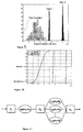
- Fig. 5 is an analysis flow chart for the example calculation. Three separate probabilistic analyses were performed for comparison:
- Fig. 8 shows histograms of the minimum flow through an individual blade for the three analyses.
- Both Class 1 and Class 3 show a significant improvement in the minimum flow observed in a set of turbine blades.
- the minimum flow of the Class 1 blades is greater than the minimum flow of any of the randomly-assembled turbine blade sets (i.e. from the Total Population results).
- Fig. 9 shows histograms of engine life for the three analyses. Both Class 1 and Class 3 show significant improvement in engine life as compared to the Total Population. Fig.
- the supply pressure is the nominal supply pressure.
- the supply pressure will increase. This increased supply pressure then leads to an increase in the flow in an individual blade.
- the mass flow perturbation in an individual blade is given by,
- the mass flow perturbation through an individual blade is controlled by two effects: the effective area perturbation for the specific blade ( ⁇ j / A g ) and the average effective area perturbation.
- the effective area perturbation for the specific blade ⁇ j / A g
- the average effective area perturbation ⁇ 0
- a low-flow blade will have reduced flow due to its own decreased effective area.
- a specific low-flow airfoil will experience less reduction in mass flow because of the negative average effective area perturbation (which results in an increased supply pressure). This effect will result in substantial improvements in the life of the turbine blades as shown in the previous example calculation.
- a low-flow blade assembled in a disk of low-flow blades will have nearly nominal mass flow.
Landscapes
- Engineering & Computer Science (AREA)
- Mechanical Engineering (AREA)
- General Engineering & Computer Science (AREA)
- Turbine Rotor Nozzle Sealing (AREA)
Applications Claiming Priority (2)
| Application Number | Priority Date | Filing Date | Title |
|---|---|---|---|
| US717408 | 2003-11-19 | ||
| US10/717,408 US7021892B2 (en) | 2003-11-19 | 2003-11-19 | Method for assembling gas turbine engine components |
Publications (3)
| Publication Number | Publication Date |
|---|---|
| EP1533476A2 true EP1533476A2 (fr) | 2005-05-25 |
| EP1533476A3 EP1533476A3 (fr) | 2008-12-10 |
| EP1533476B1 EP1533476B1 (fr) | 2016-08-10 |
Family
ID=34435756
Family Applications (1)
| Application Number | Title | Priority Date | Filing Date |
|---|---|---|---|
| EP04257082.0A Expired - Lifetime EP1533476B1 (fr) | 2003-11-19 | 2004-11-16 | Procédé d'assemblage de composants de turbine à gaz |
Country Status (5)
| Country | Link |
|---|---|
| US (1) | US7021892B2 (fr) |
| EP (1) | EP1533476B1 (fr) |
| JP (1) | JP2005147155A (fr) |
| NZ (1) | NZ536658A (fr) |
| SG (1) | SG112093A1 (fr) |
Families Citing this family (9)
| Publication number | Priority date | Publication date | Assignee | Title |
|---|---|---|---|---|
| US7280950B2 (en) * | 2004-01-22 | 2007-10-09 | Electro-Motive Diesel, Inc. | Locomotive diesel engine turbocharger and turbine stage constructed with turbine blade vibration suppression methodology |
| US7685870B2 (en) * | 2007-09-27 | 2010-03-30 | United Technologies Corporation | Systems and methods for performing cooling airflow analysis of gas turbine engine components |
| US7792600B2 (en) * | 2007-12-31 | 2010-09-07 | General Electric Company | System and a method for assembling a rotor stack |
| US7712314B1 (en) | 2009-01-21 | 2010-05-11 | Gas Turbine Efficiency Sweden Ab | Venturi cooling system |
| CN107849925B (zh) * | 2015-07-06 | 2020-03-17 | 西门子股份公司 | 具有冷却流量调节特征的涡轮机定子叶片和/或涡轮机转子叶片以及适应叶片的对应方法 |
| US20190071982A1 (en) * | 2016-03-31 | 2019-03-07 | Siemens Aktiengesellschaft | Gas turbine component selection at manufacture |
| US20180211336A1 (en) * | 2017-01-23 | 2018-07-26 | United Technologies Corporation | Classification of Gas Turbine Engine Components and Decision for Use |
| GB2580797A (en) * | 2019-01-21 | 2020-07-29 | Rolls Royce Plc | A method |
| GB2580651B (en) * | 2019-01-21 | 2021-01-27 | Rolls Royce Plc | A method |
Citations (2)
| Publication number | Priority date | Publication date | Assignee | Title |
|---|---|---|---|---|
| US4767272A (en) | 1987-10-14 | 1988-08-30 | United Technologies Corporation | Method for reducing blade tip variation of a bladed rotor |
| EP1174587A2 (fr) | 2000-07-18 | 2002-01-23 | General Electric Company | Méthode de régulation d'un courant d'air passant par un élément de construction |
Family Cites Families (3)
| Publication number | Priority date | Publication date | Assignee | Title |
|---|---|---|---|---|
| US5536143A (en) * | 1995-03-31 | 1996-07-16 | General Electric Co. | Closed circuit steam cooled bucket |
| US6247896B1 (en) * | 1999-06-23 | 2001-06-19 | United Technologies Corporation | Method and apparatus for cooling an airfoil |
| US6152698A (en) * | 1999-08-02 | 2000-11-28 | General Electric Company | Kit of articles and method for assembling articles along a holder distance |
-
2003
- 2003-11-19 US US10/717,408 patent/US7021892B2/en not_active Expired - Lifetime
-
2004
- 2004-11-16 EP EP04257082.0A patent/EP1533476B1/fr not_active Expired - Lifetime
- 2004-11-17 JP JP2004333258A patent/JP2005147155A/ja not_active Withdrawn
- 2004-11-18 NZ NZ536658A patent/NZ536658A/en unknown
- 2004-11-19 SG SG200407166A patent/SG112093A1/en unknown
Patent Citations (2)
| Publication number | Priority date | Publication date | Assignee | Title |
|---|---|---|---|---|
| US4767272A (en) | 1987-10-14 | 1988-08-30 | United Technologies Corporation | Method for reducing blade tip variation of a bladed rotor |
| EP1174587A2 (fr) | 2000-07-18 | 2002-01-23 | General Electric Company | Méthode de régulation d'un courant d'air passant par un élément de construction |
Also Published As
| Publication number | Publication date |
|---|---|
| EP1533476A3 (fr) | 2008-12-10 |
| SG112093A1 (en) | 2005-06-29 |
| US20050111975A1 (en) | 2005-05-26 |
| JP2005147155A (ja) | 2005-06-09 |
| US7021892B2 (en) | 2006-04-04 |
| NZ536658A (en) | 2006-07-28 |
| EP1533476B1 (fr) | 2016-08-10 |
Similar Documents
| Publication | Publication Date | Title |
|---|---|---|
| EP1602800B1 (fr) | Méthode de refroidissement de paroi pour une aube de turbomachine | |
| US6485255B1 (en) | Cooling air flow control device for a gas turbine engine | |
| US7094027B2 (en) | Row of long and short chord length and high and low temperature capability turbine airfoils | |
| Mayle | The role of laminar-turbulent transition in gas turbine engines | |
| Day et al. | Prediction of compressor performance in rotating stall | |
| US7021892B2 (en) | Method for assembling gas turbine engine components | |
| US7241107B2 (en) | Gas turbine airfoil with adjustable cooling air flow passages | |
| US7690894B1 (en) | Ceramic core assembly for serpentine flow circuit in a turbine blade | |
| JP2001164903A (ja) | エアフォイル及び冷却可能な壁及びその冷却方法 | |
| US20050106027A1 (en) | Turbine rotor blade for gas turbine engine | |
| US20090196737A1 (en) | Cooling airflow modulation | |
| EP0814234A1 (fr) | Aube stationnaire pour turbine a gaz | |
| Liu et al. | In-service aircraft engines turbine blades life prediction based on multi-modal operation and maintenance data | |
| CN112883575A (zh) | 一种考虑表面粗糙度的叶轮机械边界层转捩模型修正方法 | |
| US10563520B2 (en) | Turbine component with shaped cooling pins | |
| Baghdadi | Modeling tip clearance effects in multistage axial compressors | |
| US7207775B2 (en) | Turbine bucket with optimized cooling circuit | |
| Carvalho et al. | Cooling Model Calibration in a Collaborative Turbine Preliminary Design Process Using the NASA Energy Efficient Engine Part II: 1D Turbine Modeling | |
| US10669858B2 (en) | Gas turbine blade and manufacturing method | |
| EP4119775B1 (fr) | Système et procédé actif de commande de jeu pour moteur d'avion | |
| US10436048B2 (en) | Systems for removing heat from turbine components | |
| US6274215B1 (en) | Aerodynamic article with partial outer portion and method for making | |
| Astrua et al. | Axial compressor degradation effects on heavy duty gas turbines overall performances | |
| Islam et al. | Deviation in axial turbines at subsonic conditions | |
| US7581928B1 (en) | Serpentine microcircuits for hot gas migration |
Legal Events
| Date | Code | Title | Description |
|---|---|---|---|
| PUAI | Public reference made under article 153(3) epc to a published international application that has entered the european phase |
Free format text: ORIGINAL CODE: 0009012 |
|
| AK | Designated contracting states |
Kind code of ref document: A2 Designated state(s): AT BE BG CH CY CZ DE DK EE ES FI FR GB GR HU IE IS IT LI LU MC NL PL PT RO SE SI SK TR |
|
| AX | Request for extension of the european patent |
Extension state: AL HR LT LV MK YU |
|
| PUAL | Search report despatched |
Free format text: ORIGINAL CODE: 0009013 |
|
| AK | Designated contracting states |
Kind code of ref document: A3 Designated state(s): AT BE BG CH CY CZ DE DK EE ES FI FR GB GR HU IE IS IT LI LU MC NL PL PT RO SE SI SK TR |
|
| AX | Request for extension of the european patent |
Extension state: AL HR LT LV MK YU |
|
| 17P | Request for examination filed |
Effective date: 20090218 |
|
| AKX | Designation fees paid |
Designated state(s): DE FR GB |
|
| 17Q | First examination report despatched |
Effective date: 20111012 |
|
| GRAP | Despatch of communication of intention to grant a patent |
Free format text: ORIGINAL CODE: EPIDOSNIGR1 |
|
| INTG | Intention to grant announced |
Effective date: 20160226 |
|
| GRAS | Grant fee paid |
Free format text: ORIGINAL CODE: EPIDOSNIGR3 |
|
| GRAA | (expected) grant |
Free format text: ORIGINAL CODE: 0009210 |
|
| AK | Designated contracting states |
Kind code of ref document: B1 Designated state(s): DE FR GB |
|
| REG | Reference to a national code |
Ref country code: GB Ref legal event code: FG4D |
|
| REG | Reference to a national code |
Ref country code: DE Ref legal event code: R096 Ref document number: 602004049728 Country of ref document: DE |
|
| RAP2 | Party data changed (patent owner data changed or rights of a patent transferred) |
Owner name: UNITED TECHNOLOGIES CORPORATION Owner name: MASSACHUSETTS INSTITUTE OF TECHNOLOGY |
|
| REG | Reference to a national code |
Ref country code: FR Ref legal event code: PLFP Year of fee payment: 13 |
|
| REG | Reference to a national code |
Ref country code: DE Ref legal event code: R097 Ref document number: 602004049728 Country of ref document: DE |
|
| PLBE | No opposition filed within time limit |
Free format text: ORIGINAL CODE: 0009261 |
|
| STAA | Information on the status of an ep patent application or granted ep patent |
Free format text: STATUS: NO OPPOSITION FILED WITHIN TIME LIMIT |
|
| 26N | No opposition filed |
Effective date: 20170511 |
|
| REG | Reference to a national code |
Ref country code: FR Ref legal event code: PLFP Year of fee payment: 14 |
|
| REG | Reference to a national code |
Ref country code: DE Ref legal event code: R082 Ref document number: 602004049728 Country of ref document: DE |
|
| P01 | Opt-out of the competence of the unified patent court (upc) registered |
Effective date: 20230528 |
|
| PGFP | Annual fee paid to national office [announced via postgrant information from national office to epo] |
Ref country code: GB Payment date: 20231127 Year of fee payment: 20 |
|
| PGFP | Annual fee paid to national office [announced via postgrant information from national office to epo] |
Ref country code: FR Payment date: 20231127 Year of fee payment: 20 Ref country code: DE Payment date: 20231129 Year of fee payment: 20 |
|
| REG | Reference to a national code |
Ref country code: DE Ref legal event code: R071 Ref document number: 602004049728 Country of ref document: DE |
|
| REG | Reference to a national code |
Ref country code: GB Ref legal event code: PE20 Expiry date: 20241115 |
|
| PG25 | Lapsed in a contracting state [announced via postgrant information from national office to epo] |
Ref country code: GB Free format text: LAPSE BECAUSE OF EXPIRATION OF PROTECTION Effective date: 20241115 |
|
| PG25 | Lapsed in a contracting state [announced via postgrant information from national office to epo] |
Ref country code: GB Free format text: LAPSE BECAUSE OF EXPIRATION OF PROTECTION Effective date: 20241115 |