EP1533509A1 - Moteur alternatif - Google Patents
Moteur alternatif Download PDFInfo
- Publication number
- EP1533509A1 EP1533509A1 EP02743671A EP02743671A EP1533509A1 EP 1533509 A1 EP1533509 A1 EP 1533509A1 EP 02743671 A EP02743671 A EP 02743671A EP 02743671 A EP02743671 A EP 02743671A EP 1533509 A1 EP1533509 A1 EP 1533509A1
- Authority
- EP
- European Patent Office
- Prior art keywords
- piston
- reciprocating engine
- ring
- thrust side
- engine according
- Prior art date
- Legal status (The legal status is an assumption and is not a legal conclusion. Google has not performed a legal analysis and makes no representation as to the accuracy of the status listed.)
- Withdrawn
Links
Images






Classifications
-
- F—MECHANICAL ENGINEERING; LIGHTING; HEATING; WEAPONS; BLASTING
- F02—COMBUSTION ENGINES; HOT-GAS OR COMBUSTION-PRODUCT ENGINE PLANTS
- F02F—CYLINDERS, PISTONS OR CASINGS, FOR COMBUSTION ENGINES; ARRANGEMENTS OF SEALINGS IN COMBUSTION ENGINES
- F02F1/00—Cylinders; Cylinder heads
- F02F1/18—Other cylinders
-
- F—MECHANICAL ENGINEERING; LIGHTING; HEATING; WEAPONS; BLASTING
- F02—COMBUSTION ENGINES; HOT-GAS OR COMBUSTION-PRODUCT ENGINE PLANTS
- F02F—CYLINDERS, PISTONS OR CASINGS, FOR COMBUSTION ENGINES; ARRANGEMENTS OF SEALINGS IN COMBUSTION ENGINES
- F02F3/00—Pistons
-
- F—MECHANICAL ENGINEERING; LIGHTING; HEATING; WEAPONS; BLASTING
- F02—COMBUSTION ENGINES; HOT-GAS OR COMBUSTION-PRODUCT ENGINE PLANTS
- F02B—INTERNAL-COMBUSTION PISTON ENGINES; COMBUSTION ENGINES IN GENERAL
- F02B23/00—Other engines characterised by special shape or construction of combustion chambers to improve operation
-
- F—MECHANICAL ENGINEERING; LIGHTING; HEATING; WEAPONS; BLASTING
- F02—COMBUSTION ENGINES; HOT-GAS OR COMBUSTION-PRODUCT ENGINE PLANTS
- F02F—CYLINDERS, PISTONS OR CASINGS, FOR COMBUSTION ENGINES; ARRANGEMENTS OF SEALINGS IN COMBUSTION ENGINES
- F02F5/00—Piston rings, e.g. associated with piston crown
-
- F—MECHANICAL ENGINEERING; LIGHTING; HEATING; WEAPONS; BLASTING
- F16—ENGINEERING ELEMENTS AND UNITS; GENERAL MEASURES FOR PRODUCING AND MAINTAINING EFFECTIVE FUNCTIONING OF MACHINES OR INSTALLATIONS; THERMAL INSULATION IN GENERAL
- F16J—PISTONS; CYLINDERS; SEALINGS
- F16J1/00—Pistons; Trunk pistons; Plungers
- F16J1/001—One-piece pistons
-
- F—MECHANICAL ENGINEERING; LIGHTING; HEATING; WEAPONS; BLASTING
- F16—ENGINEERING ELEMENTS AND UNITS; GENERAL MEASURES FOR PRODUCING AND MAINTAINING EFFECTIVE FUNCTIONING OF MACHINES OR INSTALLATIONS; THERMAL INSULATION IN GENERAL
- F16J—PISTONS; CYLINDERS; SEALINGS
- F16J9/00—Piston-rings, e.g. non-metallic piston-rings, seats therefor; Ring sealings of similar construction
- F16J9/06—Piston-rings, e.g. non-metallic piston-rings, seats therefor; Ring sealings of similar construction using separate springs or elastic elements expanding the rings; Springs therefor ; Expansion by wedging
- F16J9/061—Piston-rings, e.g. non-metallic piston-rings, seats therefor; Ring sealings of similar construction using separate springs or elastic elements expanding the rings; Springs therefor ; Expansion by wedging using metallic coiled or blade springs
-
- F—MECHANICAL ENGINEERING; LIGHTING; HEATING; WEAPONS; BLASTING
- F16—ENGINEERING ELEMENTS AND UNITS; GENERAL MEASURES FOR PRODUCING AND MAINTAINING EFFECTIVE FUNCTIONING OF MACHINES OR INSTALLATIONS; THERMAL INSULATION IN GENERAL
- F16J—PISTONS; CYLINDERS; SEALINGS
- F16J9/00—Piston-rings, e.g. non-metallic piston-rings, seats therefor; Ring sealings of similar construction
- F16J9/06—Piston-rings, e.g. non-metallic piston-rings, seats therefor; Ring sealings of similar construction using separate springs or elastic elements expanding the rings; Springs therefor ; Expansion by wedging
- F16J9/061—Piston-rings, e.g. non-metallic piston-rings, seats therefor; Ring sealings of similar construction using separate springs or elastic elements expanding the rings; Springs therefor ; Expansion by wedging using metallic coiled or blade springs
- F16J9/063—Strip or wire along the entire circumference
-
- F—MECHANICAL ENGINEERING; LIGHTING; HEATING; WEAPONS; BLASTING
- F02—COMBUSTION ENGINES; HOT-GAS OR COMBUSTION-PRODUCT ENGINE PLANTS
- F02B—INTERNAL-COMBUSTION PISTON ENGINES; COMBUSTION ENGINES IN GENERAL
- F02B19/00—Engines characterised by precombustion chambers
- F02B19/10—Engines characterised by precombustion chambers with fuel introduced partly into pre-combustion chamber, and partly into cylinder
- F02B19/1019—Engines characterised by precombustion chambers with fuel introduced partly into pre-combustion chamber, and partly into cylinder with only one pre-combustion chamber
- F02B19/108—Engines characterised by precombustion chambers with fuel introduced partly into pre-combustion chamber, and partly into cylinder with only one pre-combustion chamber with fuel injection at least into pre-combustion chamber, i.e. injector mounted directly in the pre-combustion chamber
-
- F—MECHANICAL ENGINEERING; LIGHTING; HEATING; WEAPONS; BLASTING
- F02—COMBUSTION ENGINES; HOT-GAS OR COMBUSTION-PRODUCT ENGINE PLANTS
- F02B—INTERNAL-COMBUSTION PISTON ENGINES; COMBUSTION ENGINES IN GENERAL
- F02B19/00—Engines characterised by precombustion chambers
- F02B2019/002—Engines characterised by precombustion chambers with electric heater fitted to at least part of prechamber-wall or transfer passage
-
- F—MECHANICAL ENGINEERING; LIGHTING; HEATING; WEAPONS; BLASTING
- F02—COMBUSTION ENGINES; HOT-GAS OR COMBUSTION-PRODUCT ENGINE PLANTS
- F02B—INTERNAL-COMBUSTION PISTON ENGINES; COMBUSTION ENGINES IN GENERAL
- F02B23/00—Other engines characterised by special shape or construction of combustion chambers to improve operation
- F02B23/08—Other engines characterised by special shape or construction of combustion chambers to improve operation with positive ignition
Definitions
- the present invention relates to a reciprocating engine.
- a technique in which, to reduce sliding frictional resistance between a cylinder and a piston in the reciprocating motion of the piston, a gas chamber, into which combustion gases from a combustion chamber are introduced and in which they are stored, is formed between an inner surface of the cylinder and a side surface of the piston opposing this inner surface.
- the piston is caused to float from the inner surface of the cylinder by the gas pressure of the combustion gases in this gas chamber, thereby reducing the sliding frictional resistance between the inner surface of the cylinder and the side surface of the piston in the reciprocating motion of the piston.
- an engine in which an annular space is formed between a first piston ring disposed adjacent to an upper surface of the piston defining the combustion chamber where a fuel-air mixture is burned and a second piston ring disposed adjacent to this first piston ring.
- This annular space is partitioned into a thrust side semiannular space and an anti-thrust side semiannular space, and a gas passage is formed in a side wall of the cylinder to allow the thrust side semiannular space to communicate with the combustion chamber when the piston is located in the vicinity of the top dead center.
- the present invention has been devised in view of the above-described various aspects, and its object is to provide a reciprocating engine which makes it possible to effectively obtain a reduction in the sliding frictional resistance between the piston and the inner surface of the cylinder, and reduce the hammering sound between the piston and the inner surface of the cylinder.
- a reciprocating engine in accordance with a first aspect of the invention comprises: first and second ring grooves disposed adjacent to each other in a reciprocating direction of a piston and formed in a side surface of the piston; first and second piston rings respectively fitted in the first and second ring grooves; partitioning means for partitioning a space between the first and second piston rings into a thrust side space and an anti-thrust side space; and communicating means for allowing the thrust side space to communicate with a combustion chamber, the communicating means having a plurality of communicating passages provided in an inner surface of a cylinder, and being adapted to allow the thrust side space to communicate with the combustion chamber through the plurality of communicating passages.
- the communicating means has the plurality of communicating passages provided in the inner surface of the cylinder, and is adapted to allow the thrust side space to communicate with the combustion chamber through the plurality of communicating passages.
- the combustion gases in the combustion chamber can be introduced speedily and sufficiently into the thrust side space.
- the piston can be supported by a cushion based on the gas pressure of the combustion gases introduced into the thrust side space with respect to the slap motion and rotational motion of that piston.
- the communicating passages may be in any form, such as through holes, grooves, recesses, or the like.
- the communicating means is adapted to allow the thrust side space to communicate with the combustion chamber when the piston is located in a vicinity of a top dead center.
- the partitioning means has a hampering member disposed in the second ring groove so as to hamper mutual communication between the thrust side space and the anti-thrust side space through a gap created between a bottom surface defining the second ring groove and an inner peripheral surface of the second piston ring opposing the bottom surface.
- the partitioning means has the hampering member disposed in the second ring groove so as to hamper mutual communication between the thrust side space and the anti-thrust side space through the gap created between the bottom surface defining the second ring groove and the inner peripheral surface of the second piston ring opposing the bottom surface.
- the hampering member disposed in the second ring groove so as to hamper mutual communication between the thrust side space and the anti-thrust side space through the gap created between the bottom surface defining the second ring groove and the inner peripheral surface of the second piston ring opposing the bottom surface.
- a reciprocating engine in accordance with a fourth aspect of the invention comprises: first and second ring grooves disposed adjacent to each other in a reciprocating direction of a piston and formed in a side surface of the piston; first and second piston rings respectively fitted in the first and second ring grooves; partitioning means for partitioning a space between said first and second piston rings into a thrust side space and an anti-thrust side space; and communicating means for allowing the thrust side space to communicate with a combustion chamber, the partitioning means having a hampering member disposed in the second ring groove so as to hamper mutual communication between the thrust side space and the anti-thrust side space through a gap created between a bottom surface defining the second ring groove and an inner peripheral surface of the second piston ring opposing the bottom surface.
- the partitioning means has the hampering member disposed in the second ring groove so as to hamper mutual communication between the thrust side space and the anti-thrust side space through the gap created between the bottom surface defining the second ring groove and the inner peripheral surface of the second piston ring opposing the bottom surface.
- the hampering member disposed in the second ring groove so as to hamper mutual communication between the thrust side space and the anti-thrust side space through the gap created between the bottom surface defining the second ring groove and the inner peripheral surface of the second piston ring opposing the bottom surface.
- the communicating means has a plurality of communicating passages provided in an inner surface of a cylinder, and is adapted to allow the thrust side space to communicate with the combustion chamber through the plurality of communicating passages.
- the communicating means has the plurality of communicating passages provided in the inner surface of the cylinder, and is adapted to allow the thrust side space to communicate with the combustion chamber through the plurality of communicating passages.
- the combustion gases in the combustion chamber can be introduced speedily and sufficiently into the thrust side space.
- the piston can be supported by a cushion based on the gas pressure of the combustion gases introduced into the thrust side space with respect to the slap motion and rotational motion of that piston.
- these communicating passages may be in any form, such as through holes, grooves, recesses, or the like.
- the communicating means is adapted to allow the thrust side space to communicate with the combustion chamber when the piston is located in a vicinity of a top dead center.
- the second ring groove is disposed in the side surface of the piston such that the first ring groove is located between the same and a head end face of the piston.
- the partitioning means has the at least one pair of hampering members disposed in such a manner as to oppose each other along the axial direction of the piston pin coupling the piston and the connecting rod.
- the gas pressure of the combustion gases introduced into the thrust side space can be maintained sufficiently.
- the piston can be floatingly supported away from the thrust side inner surface of the cylinder, and the piston can be slid in a state of being closely fitted to the anti-thrust side inner surface of the cylinder.
- the partitioning means has at least one pair of partitioning members provided between the first and second piston rings, and the pair of partitioning members are disposed in such a manner as to oppose each other along the axial direction of the piston pin coupling the piston and the connecting rod.
- the partitioning means has the at least one pair of partitioning members provided between the first and second piston rings, and the pair of partitioning members are disposed in such a manner as to oppose each other along the axial direction of the piston pin coupling the piston and the connecting rod.
- the piston can be supported with the cushion based on the gas pressure of the combustion gases introduced into the thrust side space with respect to the slap motion and the rotational motion of that piston.
- it is possible to effectively obtain a reduction in the sliding frictional resistance between the piston and the cylinder in the reciprocating motion of the piston, and reduce the hammering sound between the piston and the inner surface of the cylinder.
- the partitioning member and the hampering member are disposed in such a manner as to be aligned in the reciprocating direction of the piston.
- the partitioning member and the hampering member are disposed in such a manner as to be aligned in the reciprocating direction of the piston. As such, it is possible to prevent a situation in which a gap is created between the hampering member and the partitioning member, resulting in the leakage of the combustion gases introduced into the thrust side space.
- the partitioning means has a pair of urging members for respectively urging the pair of partitioning members resiliently toward the inner surface of the cylinder.
- the partitioning means has the pair of urging members for respectively urging the pair of partitioning members resiliently toward the inner surface of the cylinder.
- the pair of urging members are respectively disposed in such a manner as to oppose each other along the axial direction of the piston pin coupling the piston and the connecting rod.
- the pair of urging members are respectively disposed in such a manner as to oppose each other along the axial direction.
- the partitioning member and the inner surface of the cylinder can be brought into close contact with each other by the resilient urging force of the pair of urging members.
- the piston can be floatingly supported away from the thrust side inner surface of the cylinder, and the piston can be slid in the state of being closely fitted to the anti-thrust side inner surface of the cylinder.
- the runout rotational motion and slap motion
- the urging member comprises a spring.
- the spring consists of, for instance, a leaf spring, a coil spring, or the like.
- the partitioning means has a pair of groove portions formed in the side surface of the piston between the first and second piston rings and recessed toward the inner surface of the cylinder, and the partitioning members are respectively disposed in spaces respectively defined by the pair of groove portions.
- the partitioning members are respectively disposed in the spaces respectively defined by the pair of groove portions, it is possible to maintain the gastightness between the thrust side space and the anti-thrust side space. Thus, it is possible to prevent the combustion gases introduced into the thrust side space from leaking to the anti-thrust side space in each operating stroke of the reciprocating engine.
- the partitioning means has a pressing member disposed in the second ring groove and adapted to resiliently press the hampering member toward the inner peripheral surface of the second piston ring.
- the partitioning means has the pressing member for resiliently pressing the hampering member toward the inner peripheral surface of the piston ring.
- the partitioning means has a pair of the pressing members opposing each other along the axial direction of the piston pin coupling the piston and the connecting rod.
- the partitioning means has the pair of the pressing members opposing each other along the axial direction of the piston pin.
- the hampering member and the inner surface of the cylinder can be brought into close contact with each other by the resilient urging force of the pair of pressing members.
- the piston can be floatingly supported away from the thrust side inner surface of the cylinder, and the piston can be slid in the state of being closely fitted to the anti-thrust side inner surface of the cylinder.
- the piston can be slid in the state of being closely fitted to the anti-thrust side inner surface of the cylinder.
- it is possible to suppress the runout of the piston.
- the pressing member comprises a spring.
- the spring consists of, for instance, a leaf spring, a coil spring, or the like.
- the partitioning means has a recessed portion disposed in the bottom surface defining the second ring groove and recessed toward the inner peripheral surface of the second piston ring, and the hampering member is disposed in a space defined by the recessed portion.
- the hampering member is disposed in the space defined by the recessed portion, it is possible to eliminate the positional offset of the hampering member occurring due to such as the gas pressure of the combustion gases introduced to the thrust side.
- the first piston ring is disposed adjacent to the head end face of the piston, and is disposed in the first ring groove such that a ring gap of the first piston ring is located on a thrust-side space side with respect to the hampering member.
- the second piston ring is disposed in the side surface of the piston such that the first piston ring is located between the same and the head end face of the piston, and the second piston ring is disposed in the second ring groove such that a ring gap of the second piston ring is located on an anti-thrust-side space side with respect to the hampering member.
- the hampering member comprises a pin.
- the pin may be integrally secured to the piston ring.
- the pin may be in any shape, such as a quadrangular prism, a cylinder, or an elliptic cylinder.
- the piston is coupled to the connecting rod by means of the piston pin, and the piston pin is provided in the piston such that a line connecting an axis of the piston pin and an axis of a crankshaft is inclined toward the anti-thrust side with respect to a line connecting a center of the piston and the axis of the crankshaft.
- the axis of the piston pin is off-centered toward the anti-thrust side relative to the center of the piston, it is possible to reduce the rotational torque of the piston acting in a direction in which the piston is strongly struck against the inner surface of the cylinder in each operating stroke of the reciprocating engine.
- the reciprocating engine in accordance with the 22nd aspect of the invention can be embodied by a four-cycle reciprocating engine, a reciprocating diesel engine, or the like, but may be embodied particularly by a reciprocating diesel engine in which the auxiliary combustion chamber is disposed on the anti-thrust side of the cylinder head portion of the cylinder.
- the reciprocating engine in accordance with any one of the first to 22nd aspects of the invention is capable of suitably exhibiting the effects derived from the invention even in a four-cycle engine, a two-cycle engine, or a diesel engine.
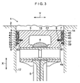
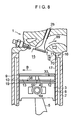
- a four-cycle reciprocating engine (four-cycle gasoline engine) 1 in accordance with this embodiment is comprised of a cylinder 2; a piston 3 reciprocating in the cylinder 2 in a direction X; a connecting rod 5 rotatably coupled at its small end portion 4 to the piston 3 through a piston pin 4a; ring grooves 7 and 8 disposed adjacent to each other in the direction X and formed in a peripheral side surface 6 of the piston 3; piston rings 9 and 10 respectively fitted in the ring grooves 7 and 8; a partitioning means 14 for partitioning an annular space 11 between the piston rings 9 and 10 into a thrust side semiannular space 12 and an anti-thrust side semiannular space 13; and a communicating means 16 for allowing the space 12 to communicate with a combustion chamber 15 where a fuel-air mixture is burned.
- the cylinder 2 has a cylindrical space 18 defined by its inner surface 17, and the piston 3 is disposed in the space 18 so as to be reciprocatable in the direction X.
- An intake valve (not shown) and an exhaust valve 2b are provided in the cylinder 2.
- the piston 3 in this embodiment has an oil ring 19 on its peripheral side surface 6.
- the connecting rod 5 is coupled at its large end portion (not shown) to a rotatable crankshaft (not shown).
- the ring grooves 7 and 8 are respectively annular along the peripheral side surface 6.
- the ring groove 7 is disposed adjacent to a head end face (top face or crown face) 23 of the piston 3 defining the combustion chamber 15, while the ring groove 8 is disposed in the peripheral side surface 6 such that the ring groove 7 is located between the same and the head end face 23.
- the piston ring (top ring or gas ring) 9 is disposed adjacent to the head end face 23.
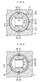
- the piston ring 9 is disposed in the ring groove 7 such that its ring gap 33 is located on the space 12 side with respect to hampering members 56 and 57.
- the piston ring 9 resiliently abuts at its outer peripheral surface 34 against the inner surface 17.
- the piston ring (second ring or gas ring) 10 is disposed on the peripheral side surface 6 such that the piston ring 9 is located between the same and the head end face 23.
- the piston ring 10 is disposed in the ring groove 8 such that its ring gap 38 is located on the space 13 side with respect to the hampering members 56 and 57.
- the piston ring 10 resiliently abuts at its outer peripheral surface 39 against the inner surface 17.
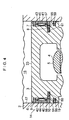
- the partitioning means 14 includes partitioning members 40 and 41 provided between the piston rings 9 and 10; a spring 42 serving as an urging member for resiliently urging the partitioning member 40 toward the inner surface 17; a spring 43 serving as an urging member for resiliently urging the partitioning member 41 toward the inner surface 17; groove portions 44 and 45 which are disposed in the peripheral side surface 6, are located between the piston rings 9 and 10, and are recessed toward the inner surface 17; the hampering members 56 and 57 disposed in the ring groove 8 so as to hamper the mutual communication between the spaces 12 and 13 through a gap created between a bottom surface 54 defining the ring groove 8 and an inner peripheral surface 55 of the piston ring 10 opposing the bottom surface 54; coil springs 58 and 59 disposed in the ring groove 8 and serving as pressing members for respectively pressing the hampering members 56 and 57 resiliently toward the inner peripheral surface 55 of the piston ring 10; and recessed portions (hole portions) 60 and 61 disposed in the bottom surface 54 and recessed toward the inner peripheral surface 55 of the piston ring 10.
- the partitioning member 40 is disposed in the space defined by the groove portion 44, while the partitioning member 41 is disposed in the space defined by the groove portion 45.
- the hampering member 56 and the coil spring 58 are disposed in the space defined by the recessed portion 60, while the hampering member 57 and the coil spring 59 are disposed in the space defined by the recessed portion 61.
- the positioning members 40 and 41, the springs 42 and 43, the groove portions 44 and 45, the hampering members 56 and 57, the coil springs 58 and 59, and the recessed portions 60 and 61 are disposed in such a manner as to oppose each other along an axial direction Y of the piston pin 4a.
- the partitioning member 40 and the hampering member 56 are respectively disposed in such a manner as to be aligned in the direction X, while the partitioning member 41 and the hampering member 57 are respectively disposed in such a manner as to be aligned in the direction X.
- the hampering members 56 and 57 are respectively disposed in the ring groove 8, and they are respectively pressed resiliently by the coil springs 58 and 59.
- the spaces 12 and 13 are hampered from communicating with each other through the ring groove 8.
- the partitioning members 40 and 41 are respectively disposed between the piston rings 9 and 10, and they are respectively pressed resiliently by the springs 42 and 43.
- the spaces 12 and 13 are hampered from communicating with each other.
- the communicating means 16 has a plurality of communicating passages 70 provided in the inner surface 17 of the cylinder 2 on the thrust side.
- the plurality of communicating passages 70 are disposed to allow the space 12 to communicate with the combustion chamber 15 through the communicating passages 70 when the piston 3 is located in the vicinity of the top dead center.
- each communicating passage 70 is defined in a recessed portion 71 formed in the inner surface 17 of the cylinder 2.
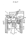
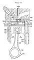
- a reciprocating diesel engine 101 in accordance with another embodiment is comprised of a cylinder 102; a piston 103 reciprocating in the cylinder 102 in the direction X; a connecting rod 105 rotatably coupled at its small end portion 104 to the piston 103 through a piston pin 104a; ring grooves 107 and 108 disposed adjacent to each other in the direction X and formed in a peripheral side surface 106 of the piston 103; piston rings 109 and 110 respectively fitted in the ring grooves 107 and 108; a partitioning means 114 for partitioning an annular space 111 between the piston rings 109 and 110 into a thrust side semiannular space 112 and an anti-thrust side semiannular space 113; and a communicating means 116 for allowing the space 112 to communicate with a main combustion chamber 115.
- the cylinder 102 has a cylindrical space 118 defined by its inner surface 117, and the piston 103 is disposed in the space 118 so as to be reciprocatable in the direction X.
- An intake valve 102a, an exhaust valve 102b, and an auxiliary combustion chamber 115a for injecting fuel ignited in the main combustion chamber 115 are provided in a cylinder head portion 155 of the cylinder 102.
- the auxiliary combustion chamber 115a communicates with the main combustion chamber 115 on the anti-thrust side, and is adapted to inject the fuel into the main combustion chamber 115 so that the injected fuel expands from the anti-thrust side toward the thrust side in the main combustion chamber 115.
- the piston 103 in this embodiment has an oil ring 149.
- the connecting rod 105 is coupled at its large end portion 150 to a rotatable crankshaft 151.
- the piston pin 104a is provided in the piston 103 such that a line L1 connecting an axis E of the piston pin 104a and an axis F of the crankshaft 151 is inclined toward the anti-thrust side with respect to a line L2 connecting a center G of the piston 103 and the axis F.
- the arrangement provided is such that the rotational torque of the piston 103 in the direction in which the piston 103 is strongly struck against the inner surface 117 of the cylinder 102 is reduced in each operating stroke of the reciprocating diesel engine 101.
- the ring grooves 107 and 108, the piston rings 109 and 110, the partitioning means 114, and the communicating means 116 are respectively formed in the same way as the ring grooves 7 and 8, the piston rings 9 and 10, the partitioning means 14, and the communicating means 16 of the above-described reciprocating engine 1. Therefore, a description thereof will be omitted.
- the communicating means 116 may be provided in that cylinder liner.
Landscapes
- Engineering & Computer Science (AREA)
- General Engineering & Computer Science (AREA)
- Mechanical Engineering (AREA)
- Chemical & Material Sciences (AREA)
- Combustion & Propulsion (AREA)
- Pistons, Piston Rings, And Cylinders (AREA)
Applications Claiming Priority (1)
| Application Number | Priority Date | Filing Date | Title |
|---|---|---|---|
| PCT/JP2002/006184 WO2004001215A1 (fr) | 2002-06-20 | 2002-06-20 | Moteur alternatif |
Publications (2)
| Publication Number | Publication Date |
|---|---|
| EP1533509A1 true EP1533509A1 (fr) | 2005-05-25 |
| EP1533509A4 EP1533509A4 (fr) | 2008-02-27 |
Family
ID=29808125
Family Applications (1)
| Application Number | Title | Priority Date | Filing Date |
|---|---|---|---|
| EP02743671A Withdrawn EP1533509A4 (fr) | 2002-06-20 | 2002-06-20 | Moteur alternatif |
Country Status (9)
| Country | Link |
|---|---|
| US (1) | US20050224038A1 (fr) |
| EP (1) | EP1533509A4 (fr) |
| KR (1) | KR20050012268A (fr) |
| CN (1) | CN1628212A (fr) |
| AU (1) | AU2002346188A1 (fr) |
| CA (1) | CA2487862A1 (fr) |
| MX (1) | MXPA04012415A (fr) |
| RU (1) | RU2304230C2 (fr) |
| WO (1) | WO2004001215A1 (fr) |
Families Citing this family (9)
| Publication number | Priority date | Publication date | Assignee | Title |
|---|---|---|---|---|
| US8069833B2 (en) * | 2006-10-20 | 2011-12-06 | Bando Kiko Co., Ltd. | Reciprocating engine |
| CN101809271B (zh) * | 2007-10-05 | 2013-06-12 | 日本活塞环株式会社 | 气缸 |
| RU2431070C1 (ru) * | 2010-06-22 | 2011-10-10 | Федеральное Государственное Образовательное Учреждение Высшего Профессионального Образования "Саратовский Государственный Аграрный Университет Имени Н.И. Вавилова" | Маслосъемное устройство цилиндропоршневой группы |
| JP5569496B2 (ja) * | 2011-09-30 | 2014-08-13 | 坂東機工株式会社 | 往復動エンジン |
| US10584639B2 (en) | 2014-08-18 | 2020-03-10 | Woodward, Inc. | Torch igniter |
| JP6090303B2 (ja) * | 2014-12-24 | 2017-03-08 | マツダ株式会社 | エンジン |
| US11421601B2 (en) | 2019-03-28 | 2022-08-23 | Woodward, Inc. | Second stage combustion for igniter |
| US12305578B2 (en) | 2020-06-23 | 2025-05-20 | Woodward, Inc. | Ignition system for power generation engine |
| JP7608309B2 (ja) | 2021-03-30 | 2025-01-06 | Tpr株式会社 | ピストンとピストンリングの組合せ構造 |
Family Cites Families (8)
| Publication number | Priority date | Publication date | Assignee | Title |
|---|---|---|---|---|
| US4681326A (en) * | 1985-06-10 | 1987-07-21 | Cummins Engine Company, Inc. | Gas lubricated piston ring assembly |
| JP2881996B2 (ja) * | 1990-08-03 | 1999-04-12 | 坂東機工株式会社 | 往復動エンジン |
| JP2929771B2 (ja) * | 1991-05-22 | 1999-08-03 | 坂東機工株式会社 | エンジン |
| JP2988010B2 (ja) * | 1991-05-22 | 1999-12-06 | 坂東機工株式会社 | エンジン |
| JP3103395B2 (ja) * | 1991-07-19 | 2000-10-30 | 坂東機工株式会社 | エンジン |
| WO1993006356A1 (fr) * | 1991-09-27 | 1993-04-01 | Bando Kiko Co., Ltd. | Moteur |
| KR970062277A (ko) * | 1996-02-29 | 1997-09-12 | 도오다 고오이찌로 | 내연 기관용 피스톤 |
| WO2004079177A1 (fr) * | 2003-03-03 | 2004-09-16 | Bando Kiko Co., Ltd. | Moteur alternatif |
-
2002
- 2002-06-20 KR KR10-2004-7020146A patent/KR20050012268A/ko not_active Ceased
- 2002-06-20 MX MXPA04012415A patent/MXPA04012415A/es unknown
- 2002-06-20 CA CA002487862A patent/CA2487862A1/fr not_active Abandoned
- 2002-06-20 US US10/517,193 patent/US20050224038A1/en not_active Abandoned
- 2002-06-20 AU AU2002346188A patent/AU2002346188A1/en not_active Abandoned
- 2002-06-20 CN CNA028291778A patent/CN1628212A/zh active Pending
- 2002-06-20 RU RU2004136590/06A patent/RU2304230C2/ru not_active IP Right Cessation
- 2002-06-20 EP EP02743671A patent/EP1533509A4/fr not_active Withdrawn
- 2002-06-20 WO PCT/JP2002/006184 patent/WO2004001215A1/fr not_active Ceased
Also Published As
| Publication number | Publication date |
|---|---|
| CA2487862A1 (fr) | 2003-12-31 |
| AU2002346188A1 (en) | 2004-01-06 |
| CN1628212A (zh) | 2005-06-15 |
| RU2304230C2 (ru) | 2007-08-10 |
| MXPA04012415A (es) | 2005-04-19 |
| KR20050012268A (ko) | 2005-01-31 |
| WO2004001215A1 (fr) | 2003-12-31 |
| US20050224038A1 (en) | 2005-10-13 |
| RU2004136590A (ru) | 2005-06-20 |
| EP1533509A4 (fr) | 2008-02-27 |
Similar Documents
| Publication | Publication Date | Title |
|---|---|---|
| RU2060400C1 (ru) | Поршневой двигатель | |
| US20050224038A1 (en) | Reciprocating engine | |
| US20050051128A1 (en) | Piston structure for reducing friction losses | |
| JP3103395B2 (ja) | エンジン | |
| CN101403347A (zh) | 用于内燃机的活塞裙部油保持件 | |
| US7464683B2 (en) | Reciprocating engine | |
| KR100976868B1 (ko) | 왕복운동 엔진 | |
| JP4133200B2 (ja) | 往復動エンジン | |
| JPH0324857Y2 (fr) | ||
| JPS621401Y2 (fr) | ||
| JP5569496B2 (ja) | 往復動エンジン | |
| JPH10184448A (ja) | 内燃機関用ピストン | |
| CN120752427A (zh) | 用于封闭活塞冷却通道的系统和方法 | |
| JP2026066080A (ja) | ピストン、内燃機関、及び、車両 | |
| KR100373249B1 (ko) | 실린더라이너상부에부연소실을형성한차량용디젤엔진 | |
| KR100626932B1 (ko) | 2사이클 디젤엔진용 피스톤 | |
| JP2011069447A (ja) | 内燃機関 | |
| US20120103310A1 (en) | Apparatus for connecting intake and exhaust valves for internal combustion engine | |
| JPH08338250A (ja) | 気筒内燃料噴射エンジンのピストン | |
| KR20020042886A (ko) | 피스톤의 구조 | |
| JP4725580B2 (ja) | 往復動エンジン | |
| JPH07253044A (ja) | 気筒内燃料噴射型エンジンのピストン | |
| JP2007040470A (ja) | ピストンリング及びピストン装置 | |
| KR19980017554A (ko) | 내연기관용 피스톤 | |
| JPH0447148A (ja) | 往復動機械 |
Legal Events
| Date | Code | Title | Description |
|---|---|---|---|
| PUAI | Public reference made under article 153(3) epc to a published international application that has entered the european phase |
Free format text: ORIGINAL CODE: 0009012 |
|
| 17P | Request for examination filed |
Effective date: 20041217 |
|
| AK | Designated contracting states |
Kind code of ref document: A1 Designated state(s): AT BE CH CY DE DK ES FI FR GB GR IE IT LI LU MC NL PT SE TR |
|
| AX | Request for extension of the european patent |
Extension state: AL LT LV MK RO SI |
|
| 18W | Application withdrawn |
Effective date: 20050613 |
|
| D18W | Application withdrawn (deleted) | ||
| DAX | Request for extension of the european patent (deleted) | ||
| A4 | Supplementary search report drawn up and despatched |
Effective date: 20080128 |
|
| STAA | Information on the status of an ep patent application or granted ep patent |
Free format text: STATUS: THE APPLICATION IS DEEMED TO BE WITHDRAWN |
|
| 18D | Application deemed to be withdrawn |
Effective date: 20080425 |