EP1533563A1 - Vorrichtung und Verfahren zur Befestigung einer Lichtquelle an einem Teil eines Kfz-Scheinwerfers - Google Patents
Vorrichtung und Verfahren zur Befestigung einer Lichtquelle an einem Teil eines Kfz-Scheinwerfers Download PDFInfo
- Publication number
- EP1533563A1 EP1533563A1 EP04292699A EP04292699A EP1533563A1 EP 1533563 A1 EP1533563 A1 EP 1533563A1 EP 04292699 A EP04292699 A EP 04292699A EP 04292699 A EP04292699 A EP 04292699A EP 1533563 A1 EP1533563 A1 EP 1533563A1
- Authority
- EP
- European Patent Office
- Prior art keywords
- lamp
- bulb
- counterpart
- ring
- light source
- Prior art date
- Legal status (The legal status is an assumption and is not a legal conclusion. Google has not performed a legal analysis and makes no representation as to the accuracy of the status listed.)
- Granted
Links
Images


Classifications
-
- F—MECHANICAL ENGINEERING; LIGHTING; HEATING; WEAPONS; BLASTING
- F21—LIGHTING
- F21V—FUNCTIONAL FEATURES OR DETAILS OF LIGHTING DEVICES OR SYSTEMS THEREOF; STRUCTURAL COMBINATIONS OF LIGHTING DEVICES WITH OTHER ARTICLES, NOT OTHERWISE PROVIDED FOR
- F21V25/00—Safety devices structurally associated with lighting devices
-
- F—MECHANICAL ENGINEERING; LIGHTING; HEATING; WEAPONS; BLASTING
- F21—LIGHTING
- F21S—NON-PORTABLE LIGHTING DEVICES; SYSTEMS THEREOF; VEHICLE LIGHTING DEVICES SPECIALLY ADAPTED FOR VEHICLE EXTERIORS
- F21S41/00—Illuminating devices specially adapted for vehicle exteriors, e.g. headlamps
- F21S41/10—Illuminating devices specially adapted for vehicle exteriors, e.g. headlamps characterised by the light source
- F21S41/14—Illuminating devices specially adapted for vehicle exteriors, e.g. headlamps characterised by the light source characterised by the type of light source
- F21S41/17—Discharge light sources
-
- F—MECHANICAL ENGINEERING; LIGHTING; HEATING; WEAPONS; BLASTING
- F21—LIGHTING
- F21S—NON-PORTABLE LIGHTING DEVICES; SYSTEMS THEREOF; VEHICLE LIGHTING DEVICES SPECIALLY ADAPTED FOR VEHICLE EXTERIORS
- F21S41/00—Illuminating devices specially adapted for vehicle exteriors, e.g. headlamps
- F21S41/10—Illuminating devices specially adapted for vehicle exteriors, e.g. headlamps characterised by the light source
- F21S41/19—Attachment of light sources or lamp holders
- F21S41/192—Details of lamp holders, terminals or connectors
Definitions
- the invention relates to a system for fixing a light source on a counterparty of a motor vehicle headlamp.
- the invention in particular, a fastening system which makes it possible to fix different types of light sources incorporating a discharge lamp.
- the invention finds applications in the automotive field and, more specifically, in the field of light projection for motor vehicles. It finds, in particular, applications for the fixation of a light source with possibility of interchangeability between light sources of different types.
- light projection devices for motor vehicles are equipped with light sources which can be of different kinds.
- front projectors vehicles are equipped with light sources that can be two different types, namely: a first kind with a halogen bulb, and a second kind to discharge bulb.
- the source luminaire is also equipped with a high voltage module which ensures the power supply of the discharge lamp.
- lamp D1 and D2 lamp there are currently two types of light sources called lamp D1 and D2 lamp.
- Each of these light sources, or lamps has a discharge bulb, a bulb foot and a high voltage module.
- the high voltage module is immovably fixed in the case of a D1 lamp and, conversely, removably in the case of a lamp D2.
- the high voltage module makes integral part of the lamp.
- the high module voltage is not built into the lamp; it constitutes a piece independent, removably mounted on the lamp.
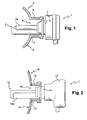
- FIG. Figure shows a light source 1 having a discharge bulb 2, a bulb foot 4 and a high voltage module 3.
- the bulb 2 is fixed solidarily to module 3 at the foot of the bulb foot 4.
- a reflector 5 is provided with an orifice 6 for passage at a base 7. By the orifice 6 passes the bulb 2.
- a body 2a of the bulb 2 is housed inside
- the bulb foot 4 is located outside the reflector 5.
- a lamp holder 8 circular cylindrical shape, forms an integral part of the reflector 5.
- the lamp holder 8 and the reflector 5 together form a single and even coin called counterpart 9 of the projector.
- the lamp holder 8 has for role of supporting the discharge lamp 2. It also allows centering and orienting the discharge bulb 2 inside the reflector 5.
- the lamp holder 8 may also be a separable part of the reflector 5.
- the lamp holder 8 is then not an integral part of the reflector; it is fixed solidly to the reflector at the time of mounting the projector.
- the door lamp 8 and the reflector form, in this case too, the counterpart of projector.
- the discharge lamp 2 is surmounted a high voltage module 3, integral with said bulb.
- This module 3 has a substantially square outer contour with a relatively small footprint compared to a lamp D2 and its module, which will be described later.
- module 3 is irremovable leads to some disadvantages. Indeed, when a user is eager to change the discharge lamp of a headlamp from his vehicle, for example because that it is failing, it is obliged to change all the bulb and high voltage module. In addition, the change of this whole bulb and high voltage module is relatively difficult because, on the one hand, of the difficulty accessing the D1 lamp and the operations to be performed to remove the faulty set and install the new set and the fact, on the other hand, risks due to the high voltage present in the module. The user is obliged to have the whole thing changed by a professional, which drive, in addition to the cost of all, a cost of labor.
- FIG. 2 An example of a D2 lamp with its high voltage module is represented in FIG. 2.
- This FIG. 2 shows a light source 11 including a discharge lamp 12.
- a high-voltage electrical module 13 is removably attached to the bulb 12 at the location of a foot 14.
- a reflector 15 is provided at the location of the base 17 with an orifice passage 16 passing the bulb 12.
- the body 12a of the bulb 12 is housed inside the reflector 15.
- the bulb foot 14 is located at the outside of the reflector 15.
- the lamp D2 comprises a lamp holder 18, for example of circular cylindrical shape, which can make integral part of the reflector 15, or be a separate piece, solidary of the reflector 15.
- the lamp holder 18 and the reflector 15 together form the counterpart 19 of the projector.
- the bulb has no electronics associated, that is to say that the high voltage module is independent of the bulb.
- the high voltage module is not part of integral part of the discharge lamp: it is attached to the bulb after the place the bulb in the reflector. It is therefore possible, during assembly and disassembling the projector, disconnecting the high-voltage module from the bulb.
- This has a certain advantage over the lamp D1.
- a lamp D2 it is possible, when the bulb is defective, to change only the bulb and keep the original high voltage module.
- changing a bulb in a D2 lamp is still more delicate than changing the entire bulb and module for a D1 lamp.
- the user in the difficult place of access that is a projector, the user must first remove the module, and remove the bulb; he must then change the bulb and put the module back on the bulb, with all the risks inherent to the high voltage in the module. The user is therefore obliged to have the bulb changed by a professional.
- this type of light source discharge lamp connected to a high-voltage module, shall include means which make it possible, on the one hand, to provide electrical continuity and, on the other hand, a shield to prevent leakage of the electromagnetic field.
- this type of light source because of the generation of a high voltage by the high voltage module, the light projector is subject to many electromagnetic radiation. In order to avoid a dispersion of the electromagnetic radiation inside the vehicle, a shielding the light projection device is necessary. Indeed, electromagnetic radiation can generate many disturbances in the electrical assembly of the vehicle. Several functions of a current motor vehicle being managed by an electronic system, these electromagnetic disturbances can have consequences serious.
- the object of the invention is precisely to solve the disadvantages of techniques previously exposed by allowing to fix a light bulb on a projector counterpart, with the same fastening system for a D1 lamp only for a D2 lamp.
- the invention proposes a system for fixing a light source with a discharge bulb adaptable for different types of light sources.
- This system is particularly suitable for gas-discharge light sources, such as the D1 and D2 lamps, because it ensures continuity electrical and electromagnetic shielding to prevent field leakage electromagnetic into the vehicle.
- the invention also relates to a motor vehicle, characterized in that it comprises at least one light projection device previous.
- Figure 1 already described, shows a longitudinal sectional view a conventional vehicle headlamp with a D1 lamp.
- Figure 2 already described, shows a longitudinal sectional view a conventional vehicle headlamp with a D2 lamp and a module high tension.
- Figures 3A and 3B each represent a perspective view of the fixation system of the invention, respectively, in the case where the system is unlocked and in case the system is locked, in the case of a D2 lamp.
- FIG. 4 represents the fastening system of the assembled invention around a light source D2.
- FIG. 5 represents the fastening system of the assembled invention around a light source D1.
- Figs. 6A to 6D show side sectional views and sectional views of the fixing system of the invention, in the case where it's unlocked and in the case where it's locked, for a source luminous D1.
- Figs. 7A to 7D show side sectional views and sectional views of the fixing system of the invention, in the case where it's unlocked and in the case where it's locked, for a source bright D2.
- the lamps D1 and D2 have shapes very different from each other. They still have some common, standardized.
- This common part is the bulb foot. Foot bulb is the rear part of the discharge bulb through which this is attached to the high voltage module.
- This bulb foot is substantially cylindrical, with the same diameter for the D1 and D2 lamps.
- height between the neck of the bulb foot and the base of the high voltage module can vary between a D1 lamp and a D2 lamp. Indeed, in the case of a D1 lamp, this height is normalized. On the other hand, in the case of a lamp D2, this height depends on the high voltage module used.
- the invention therefore proposes to use this characteristic common to two lamps. More specifically, it proposes to fix a fastening system a lamp D1 or a lamp D2 around this common part.
- the fixation system of the invention is therefore intended to be positioned around the bulb foot of a light source D1 or D2. This fastening system allows to hold and lock the discharge bulb with the door lamp, that is to say the upper part of the counterpart of the projector, in the of the bulb foot.
- FIGS. 3A and 3B This fastening system of the invention is shown in FIGS. 3A and 3B, in perspective views. More specifically, Figure 3A shows the system in an unlocked position and Figure 3B shows the system in its locked position.
- FIG. 3A shows the fastening system mounted on the counterpart 19, in the case of a lamp D2 for which the high module voltage has not yet been attached to the bulb foot 14.
- This system of fastener 20 comprises a rigid ring 21 and a flexible ring 31.
- the ring flexible 31 is electrically conductive. It is placed inside the ring rigid 21.
- the rigid ring 21 is movable in rotation.
- the flexible ring 31 is not mobile in rotation with respect to counterparty 19. However, it has a degree of freedom, which is a radial translation, with respect to the counterpart of the projector. In other words, as we will see later, the flexible ring 31 can move radially toward the bulb foot, under the effect of a pressure exerted by the rigid ring 21.
- the flexible ring 31 is made of a flexible material and electrically conductive, for example a metallic material. He rocks thus an electric function, at the same time, by internal contact on the counterpart and by contact of the contact tabs on the high module voltage.
- This flexible ring 31 has a relatively circular shape; more precisely, it has a circular shape when the fastening system is in locked position; it is circular by segment, or sector, when the fastening system is in the unlocked position.
- the flexible ring has a larger tangential pitch at a point than in a another point, that is to say greater at the end of the segment than at the beginning of segment. This can be done by shearing the ring at the end of the segment, this which puts the end of the segment naturally behind the rest of the segment.
- One or more of these different tongues can ensure, in addition, a pre-hold role of the lamp on the counterpart, before the lamp lock is achieved. This tongue then allows the lamp is stable on the counterpart, in a position ready to be locked.
- the contact tabs are thin and long so to come into contact with an electrically conductive part of the lamp.
- the holding tabs are wider than the contact tabs, in order to prevent any change of position of the lamp in the counterpart, when the system is in the locked position.
- the tongue of positioning is fine and long so as to break into a dwelling of the lamp.
- Each tongue has a substantially vertical sidewall 34 and a base 35 substantially horizontal.
- the flank has a free end and a common end with one side of the base.
- the opposite side of the base flank is connected to a flange 36 which connects several tabs between them.
- the tabs are divided into several sectors. There are so many sectors of tabs that there are tabs of maintenance. Each sector, or segment, therefore has a holding tab and several contact tabs, the retaining tab being placed at the end of sector.
- One of the sectors may also include a tab of positioning.
- the flank of the contact tongues may have a shape more or less curve, forming at least one arc of a circle, so as to give flexibility to the tabs to allow better contact with the high module voltage.
- the holding tongues comprise, in addition to a sidewall 34 and a base 35, a holding arm 37 located in the same plane as the base 35, perpendicular to the sidewall 34 and directed towards the bulb foot 14. It is this arm 37 which serves to maintain the foot in the counterpart, when the fastening system is in its locked position.
- a holding arm 37 located in the same plane as the base 35, perpendicular to the sidewall 34 and directed towards the bulb foot 14. It is this arm 37 which serves to maintain the foot in the counterpart, when the fastening system is in its locked position.
- several holding tabs for example three, distributed symmetrically on the flexible ring, that is to say around the bulb foot, it ensures a fixed positioning of the bulb foot inside the ring flexible and therefore the counterpart.
- the positioning tab comprises, in addition to a sidewall 34 and a base 35, a housing arm located in the same plane as the base 35, perpendicular to the sidewall 34 and directed towards the bulb foot 14. This arm of housing is intended to fit into a lamp housing for ensure correct single positioning of the bulb in the counterpart.
- the tabs for holding and all have a flank 34.
- This sidewall 34 allows these tongues to ensure, in addition to their respective roles of maintaining and positioning, a role of electrical conduction and shielding electromagnetic as well as the contact tabs.
- the flank of the retaining tabs has approximately the same shape curve as the contact tabs.
- these tabs for holding and positioning may not have flanks; in this case, they only provide their initial role, namely the maintenance and positioning of the bulb in the counterparty.
- the flexible ring can be made by cutting and folding in a metal foil whose type of metal and thickness are chosen according the desired flexibility. Tabs can also be folded with different shapes and sizes depending on their role. In particular, contact tabs may have a curved shape ensuring better electrical contact with the lamp.
- the flexible ring 31 which has just been described, is installed in a rigid ring 21.
- the sectors of the flexible ring are placed side by side, so that the tab of maintenance of a sector is next to a contact tongue of another sector.
- the rigid ring 21 is made of a plastic material or metallic. It has a circular shape, by segment.
- the ring rigid 21 is formed of several segments, for example three, solidary the each other. Each segment forms an arc, connected to another segment by a setback.
- the ring rigid 21 has three segments 21a, 21b and 21c. Segment 21a (and respectively 21b and 21c) is separated from segment 21b (and respectively 21c and 21a) by a recess 23a (and respectively 23b and 23c).
- the recesses have the advantage of facilitating gripping of the ring by the user to rotate it.
- the rigid ring 21 has first lugs 22a, 22b (called also prominent parts) forming cams.
- first lugs 22a, 22b (called also prominent parts) forming cams.
- the rigid ring has as many first lugs as the flexible ring has tabs of maintenance.
- the rigid ring therefore comprises three first lugs, only two being visible in the figure. These pins are intended, in the locked position, to push the holding tabs towards the foot of bulb.
- the rigid ring may comprise a second lug, not shown on Figure 3A, forming a cam. This second lug is intended, in position locked, to put the positioning tab in a housing of the lamp to ensure correct positioning of said lamp.
- the rigid ring is made so that the flexible ring is against the inner face of said ring and blocked, upwards, by the lugs of the ring.
- the flexible ring can also be blocked, towards the low, by other lugs used to secure the entire fastening system on the counterparty.
- the rigid ring 21 has the role of ensuring the locking and the unlocking the fastening system by a rotation about an axis XX 'of the system, that is to say by a rotation relative to the flexible ring and by compared to the counterparty.
- the rigid ring is rotatable while the flexible ring is not rotatable relative to the counterparty.
- the rigid ring may comprise, on its inner face, a boss in hard points to prevent the ring from returning to position free. This allows to unlock but not to return to position free.
- the fastening system is in position unlocked.
- the rigid ring is therefore in the open position with respect to the flexible ring.
- the retaining tabs 32 of the flexible ring are positioned each close to a recess the rigid ring; the lugs 22 of the rigid ring are placed in front of contact tabs and do not press on any tab.
- the flexible ring is therefore free from any contact or support with a lamp.
- the flexible ring By turning the rigid ring, for example at an angle of about 40 °, the flexible ring is supported by the lug at its most off-center level, that is to say at the level of the retaining tab.
- Each pin 22a, 22b then comes resting against a retaining tab 32a, 32b pushing this tongue towards the bulb foot 14. Under the effect of the pushing by the pin, the tongue of maintenance is found near the foot of bulb, even in support against the bulb foot, which prevents the bulb from move in the counterpart.
- Figure 3B shows the fastening system of the invention in a locked position, that is to say after rotation of the rigid ring.
- This figure shows that, in this locked position, the lugs 22c, 22a of the ring rigid 21 press on the retaining tabs 32c, 32a of the ring 31.
- the retaining tabs are then pushed into the interior of the system, that is to say towards the bulb foot 14. They can thus be in support against the lamp and, in particular, the bulb foot.
- the high voltage module can then be placed around the bulb foot.
- the high voltage module is then in contact with all or part of the contact tabs 33, which creates a electrical contact between the high voltage module and these tabs. More of this electrical contact, the contact tabs make it possible to electromagnetic radiation emitted between the high-voltage module and the other point of view. This ensures an electromagnetic shielding between the High voltage module and the counterpart.
- FIG. 4 represents the fastening system of the assembled invention around a light source D2, when the system is locked.
- This Figure shows the counterpart 19 of the projector, with its reflector 15 and its lamp holder 18, on which is mounted the fixing system 20 of the invention and the lamp D2.
- the tabs of contact 33 of the fastening system 20 are in electrical contact with the high voltage module of the light source D2. More specifically, in the case of a lamp D2, the contact tongues are in contact with the lamp connector D2.
- the holding tongues 32 are in support against the bulb foot.
- FIG. 5 represents the fastening system of the assembled invention around a light source D1, when the system is locked.
- This FIG. 5 shows the counterpart 9 of the projector, with the reflector 5 and the door lamp 8, on which is mounted the fixing system 20 of the invention and the D1 lamp. It can be seen in this FIG. 5 that the contact tabs 33 of the fastening system 20 are in electrical contact with the lamp D1, by a metal part of the lamp under the connector 3.
- contact tabs are not present all around the circumference of the flexible ring, but on parts only.
- the area on which a pin will be rotated may not have a tab to make a flat surface between the initial position and the final position of the pin, that is to say between the position unlocked and the locked position of the lug.
- Figures 4 and 5 show that the space between the fastening system 20 and the high voltage module 3 of a lamp D1 is weaker than that between the fixing system and the high voltage module of a lamp D2.
- the module of a lamp D1 has a square shape whose base has dimensions greater than the diameter of the fastening system.
- base of the lamp module D2 has a smaller diameter than the system of fixation.
- the contact tabs therefore have different dimensions in the case of a lamp system D1 and a lamp system D2.
- the contact tongues for lamp D2 are longer than the contact tabs for lamp D1, since they come into contact with the module itself.
- the lamp contact tabs D1 come into contact with a part located below the module, that is to say closer to the bulb foot; they are therefore shorter.
- the curvature of the contact tabs may also vary depending on the lamp considered.
- the fastening system of the invention is therefore identical for D1 lamps and for D2 lamps, except the flexible ring which can have different tongue lengths. As will be understood afterwards, this difference is not a problem, in the sense that it does not hinder in no way the interchangeability of the lamps.
- the fixing system is positioned and fixed according to the following procedure: first of all the system of fixing is done by assembling the flexible ring, adapted to a D1 lamp or to a lamp D2, with the rigid ring, then inserting this system vertically on the top of the counterpart. The system is then fixed on this counterpart by conventional means, for example, in force, by bayonet or snap.
- the fixing system can have, in its part located below the flexible ring, lugs to fix the mounting system on the counterpart of the projector.
- the lamp In the case of a lamp D1, the lamp is positioned on the system fastening by placing the discharge bulb inside the counterpart, in a V-shaped accommodation of the counterparty.
- the position of the lamp D1 in the fastening system is correct when the tongue of positioning is in support against the lamp D1, pushing said lamp to bottom of the V-shaped housing.
- the fastening system is put in locked position by gagging, that is to say by a rotation of the rigid ring around the axis XX 'and therefore a rotation of the rigid ring relative to the ring flexible.
- the discharge lamp is placed in inside the counterpart, the bulb foot being positioned on the fastening system.
- the position of the D2 lamp in the fixing system is correct when the lamp is in the V-shaped housing of the counterpart and that the positioning tab bears against the D2 lamp, pushing it to the bottom of the V-shaped housing.
- the lamp D2 is correctly inserted into the counterpart, the system of fastening is put in the locked position by gagging, that is by a rotation of the rigid ring about the axis XX 'and therefore a rotation of the rigid ring relative to the flexible ring.
- the high voltage module can then be set up on the bulb foot.
- the positioning tab is a spring blade that allows push the lamp to the bottom of the V-shaped housing made in the counterparty.
- the role of this positioning tab is to catch up with games that can be between the lamp and the counterpart by pushing the lamp radially in the V-shaped housing in the counterpart.
- the positioning tab is placed radially opposite the V. rigid ring, when it is placed in the locked position, has a lug which pushes the positioning tab towards the center of the system, pushing the lamp radially so that it is wedged in the housing in V-shape of the counterpart.
- the positioning tab can also be used as a key, when the fitting of the lamp to the counterpart, that is to say that it offers a only possible position during assembly.
- FIGS. 6A and 6C sectional side views are shown in section of the fixing system of the invention, in the case of a lamp D1, when the system is, respectively, unlocked and locked.
- Figures 6B and 6D represent top views of the fastening system of the invention, in the case of a lamp D1, when the system is, respectively, unlocked and locked.
- Figures 6A and 6B show the position of the rigid ring 21 and the flexible ring 31 when the system is unlocked. In particular, they show the position of the first lugs 22a, 22b, 22c of the ring rigid relative to the retaining tabs 32a, 32b, 32c of the ring flexible. These figures also show the position of the second lug 28 by relative to the positioning tabs 38 of the flexible ring 31.
- the positioning tongue 38 In unlocked position, the positioning tongue 38 is housed in a housing the bulb foot, but it is angled in this housing. The locking the system allows this tab to exert a push radial on the lamp to push the lamp to the bottom of the housing fit V's counterparty.
- This V-shaped housing is shown in FIG. two flats 40 located, radially, opposite the housing 39 receiving the positioning tab 38.
- FIGS. 6A and 6B also show the positioning of the contact tabs 33, between the tabs of 32. It is thus easy to see the differences in size that can be have between the different kinds of tabs.
- FIGS. 6C and 6D show the fastening system in the case of a D1 lamp, when the system is locked.
- the first and the second lugs of the ring do not press on any tongue.
- the rigid ring is rotated about 40 °, by compared to the flexible ring, the first lugs 22 come to stand before the holding tongues 32 and the second lug 28 in front of the tongue of positioning 38.
- the placement of these pins can be done ordinate, that is to say that the second lug 28 is placed before the first 22.
- This rotation of the rigid ring has the effect of pushing holding tabs towards the bulb foot, making the ring flexible totally circular. This also has the effect of pushing the tongue positioned at the bottom of his dwelling 39, allowing him to exercise pressing the lamp D1 in the housing in V.
- the rigid ring 21 thus acts as a cam on the flexible ring 31.
- FIGS. 7A and 7C show side views, in section, of the fixation system of the invention, in the case of a lamp D2, when the system is, respectively, unlocked and locked.
- Figures 7B and 7D represent top views of the fastening system of the invention, in the case of a lamp D2, when the system is, respectively, unlocked and locked.
- Figures 7A and 7B show the position of the rigid ring 21 and the flexible ring when the system is unlocked. In particular, they show the position of the first lugs 22a, 22b, 22c of the ring rigid relative to the retaining tabs 32a, 32b, 32c of the ring flexible.
- These figures also show the position of the second lug 28 by relative to the positioning tabs 38 of the flexible ring 31.
- the positioning tongue 38 In unlocked position, the positioning tongue 38 is housed in a housing the bulb foot, but it is angled in this housing ..
- the locking the system allows this tab to exert a push radial on the lamp to push the lamp to the bottom of the housing fit V's counterparty.
- This V-shaped housing is represented in FIG. 7B by two flats 40 located, radially, opposite the housing 39 receiving the positioning tab 38.
- FIGS. 7A and 7B also show the positioning of the contact tabs 33, between the tabs of 32. It is thus easy to see the differences in size that can be have between the different kinds of tabs.
- Figures 7C and 7D show the fastening system in the case a D2 lamp, when the system is locked.
- the rigid ring is rotated about 40 °, by compared to the flexible ring, the first lugs 22 come to stand before the holding tongues 32 and the second lug 28 in front of the tongue of positioning 38.
- the placement of these pins can be done ordinate, that is to say that the second lug 28 is placed before the first 22.
- This rotation of the rigid ring has the effect of pushing holding tabs towards the bulb foot, making the ring flexible totally circular. This also has the effect of pushing the tongue positioned at the bottom of his dwelling 39, allowing him to exercise pressing the lamp D2 in the housing in V.
- the ring flexible 31 ensures the mechanical strength and positioning of a D1 lamp or D2 on the counterpart, as well as electrical continuity and shielding electromagnetic between the counterpart and the high voltage module. Before locking, it acts as a pre-hold of the lamp because the diameter inside the circle on which are distributed the holding tabs, in unlocked position, is less than the outside diameter of the base of the lamp.
- the projector is standard for a D1 lamp and for a D2 lamp. It can therefore be produced in mass production, in production, and it is simply at the moment of the installation of the light source that one choose, if necessary, to take a flexible ring with large tabs of contact, for a lamp D2, or with small tongues of contact, for a D1 lamp. It is thus possible to mount a lamp D1 or a lamp D2, as desired, depending on the cost and availability of either lamp.
Landscapes
- Engineering & Computer Science (AREA)
- General Engineering & Computer Science (AREA)
- Non-Portable Lighting Devices Or Systems Thereof (AREA)
Applications Claiming Priority (2)
| Application Number | Priority Date | Filing Date | Title |
|---|---|---|---|
| FR0313650A FR2862744B1 (fr) | 2003-11-21 | 2003-11-21 | Systeme de fixation d'une source lumineuse sur une contrepartie d'un projecteur de vehicule automobile et procede de mise en oeuvre |
| FR0313650 | 2003-11-21 |
Publications (2)
| Publication Number | Publication Date |
|---|---|
| EP1533563A1 true EP1533563A1 (de) | 2005-05-25 |
| EP1533563B1 EP1533563B1 (de) | 2018-04-25 |
Family
ID=34430036
Family Applications (1)
| Application Number | Title | Priority Date | Filing Date |
|---|---|---|---|
| EP04292699.8A Expired - Lifetime EP1533563B1 (de) | 2003-11-21 | 2004-11-15 | Vorrichtung und Verfahren zur Befestigung einer Lichtquelle an einem Teil eines Kfz-Scheinwerfers |
Country Status (4)
| Country | Link |
|---|---|
| US (1) | US7241042B2 (de) |
| EP (1) | EP1533563B1 (de) |
| JP (1) | JP4554339B2 (de) |
| FR (1) | FR2862744B1 (de) |
Cited By (1)
| Publication number | Priority date | Publication date | Assignee | Title |
|---|---|---|---|---|
| FR2880674A1 (fr) * | 2005-01-07 | 2006-07-14 | Valeo Vision Sa | Systeme de fixation d'une lampe sur un porte lampe de projecteur pour vehicule automobile |
Families Citing this family (7)
| Publication number | Priority date | Publication date | Assignee | Title |
|---|---|---|---|---|
| US20060291216A1 (en) * | 2005-06-14 | 2006-12-28 | Blumel Daniel M | Apparatus for reducing in size an igniter circuit and assembly |
| KR100726168B1 (ko) | 2005-11-08 | 2007-06-13 | 현대자동차주식회사 | 차량의 벌브 홀더유닛 |
| FR2895063A1 (fr) * | 2005-12-20 | 2007-06-22 | Valeo Vision Sa | Porte lampe de projecteur equipe de griffes orientees tangentiellement par rapport a la paroi du porte lampe |
| US7646151B2 (en) * | 2006-02-06 | 2010-01-12 | General Electric Company | Light source module |
| DE102007022028B4 (de) * | 2007-05-11 | 2016-10-20 | Automotive Lighting Reutlingen Gmbh | Beleuchtungseinrichtung für ein Fahrzeug, insbesondere Kraftfahrzeugscheinwerfer |
| JP5368880B2 (ja) * | 2009-05-29 | 2013-12-18 | 株式会社小糸製作所 | 車両用灯具 |
| AT513724B1 (de) * | 2012-12-10 | 2014-09-15 | Zizala Lichtsysteme Gmbh | Vorrichtung zum Festlegen einer Lampe |
Citations (5)
| Publication number | Priority date | Publication date | Assignee | Title |
|---|---|---|---|---|
| US4819133A (en) * | 1987-07-15 | 1989-04-04 | Stanley Electric Co., Ltd. | Replaceable headlamp assembly |
| US5144189A (en) * | 1987-03-06 | 1992-09-01 | U.S. Philips Corporation | Automotive high voltage discharge lighting system and assembly |
| FR2742709A1 (fr) * | 1995-12-20 | 1997-06-27 | Bosch Gmbh Robert | Phare pour vehicule avec reflecteur |
| DE29908298U1 (de) * | 1999-05-08 | 2000-09-21 | Robert Bosch Gmbh, 70469 Stuttgart | Beleuchtungseinrichtung für Fahrzeuge |
| EP1283390A2 (de) * | 2001-08-10 | 2003-02-12 | Ichikoh Industries, Ltd. | Scheinwerfer mit zwei Funktionen |
Family Cites Families (8)
| Publication number | Priority date | Publication date | Assignee | Title |
|---|---|---|---|---|
| US4403276A (en) * | 1980-12-03 | 1983-09-06 | GTE Products Corporation_ | Front loading projection unit with snap in capsule |
| US4392189A (en) * | 1980-12-03 | 1983-07-05 | Gte Products Corporation | Front loading projection unit with threaded resilient retention member |
| DE3837511A1 (de) * | 1988-11-04 | 1990-05-10 | Philips Patentverwaltung | Kraftfahrzeugscheinwerferlampe und verfahren zu ihrer herstellung |
| JP3126640B2 (ja) * | 1995-08-25 | 2001-01-22 | 株式会社小糸製作所 | 車輌用灯具におけるバルブ固定構造 |
| CN1094651C (zh) * | 1995-08-30 | 2002-11-20 | 皇家菲利浦电子有限公司 | 电反射灯 |
| DE19538064A1 (de) * | 1995-10-13 | 1997-04-17 | Bosch Gmbh Robert | Entladungslampe, insbesondere für Fahrzeugbeleuchtungssysteme |
| JP3316629B2 (ja) * | 1999-05-14 | 2002-08-19 | スタンレー電気株式会社 | 車両用放電灯点灯ユニット |
| JP4008250B2 (ja) * | 2002-01-31 | 2007-11-14 | 株式会社小糸製作所 | 車輌用前照灯 |
-
2003
- 2003-11-21 FR FR0313650A patent/FR2862744B1/fr not_active Expired - Lifetime
-
2004
- 2004-11-15 EP EP04292699.8A patent/EP1533563B1/de not_active Expired - Lifetime
- 2004-11-19 JP JP2004336105A patent/JP4554339B2/ja not_active Expired - Fee Related
- 2004-11-19 US US10/994,104 patent/US7241042B2/en not_active Expired - Lifetime
Patent Citations (5)
| Publication number | Priority date | Publication date | Assignee | Title |
|---|---|---|---|---|
| US5144189A (en) * | 1987-03-06 | 1992-09-01 | U.S. Philips Corporation | Automotive high voltage discharge lighting system and assembly |
| US4819133A (en) * | 1987-07-15 | 1989-04-04 | Stanley Electric Co., Ltd. | Replaceable headlamp assembly |
| FR2742709A1 (fr) * | 1995-12-20 | 1997-06-27 | Bosch Gmbh Robert | Phare pour vehicule avec reflecteur |
| DE29908298U1 (de) * | 1999-05-08 | 2000-09-21 | Robert Bosch Gmbh, 70469 Stuttgart | Beleuchtungseinrichtung für Fahrzeuge |
| EP1283390A2 (de) * | 2001-08-10 | 2003-02-12 | Ichikoh Industries, Ltd. | Scheinwerfer mit zwei Funktionen |
Cited By (3)
| Publication number | Priority date | Publication date | Assignee | Title |
|---|---|---|---|---|
| FR2880674A1 (fr) * | 2005-01-07 | 2006-07-14 | Valeo Vision Sa | Systeme de fixation d'une lampe sur un porte lampe de projecteur pour vehicule automobile |
| US7517124B2 (en) | 2005-01-07 | 2009-04-14 | Valeo Vision | System for fixing a lamp to a headlight lamp holder for an automobile |
| EP1679472A3 (de) * | 2005-01-07 | 2013-07-31 | Valeo Vision | Vorrichtung zur Befestigung einer Lampe auf einer Lampenfassung für Kfz-Scheinwerfer |
Also Published As
| Publication number | Publication date |
|---|---|
| JP4554339B2 (ja) | 2010-09-29 |
| JP2005158738A (ja) | 2005-06-16 |
| EP1533563B1 (de) | 2018-04-25 |
| US20050111230A1 (en) | 2005-05-26 |
| US7241042B2 (en) | 2007-07-10 |
| FR2862744A1 (fr) | 2005-05-27 |
| FR2862744B1 (fr) | 2006-09-29 |
Similar Documents
| Publication | Publication Date | Title |
|---|---|---|
| EP3044500B1 (de) | Lichtmodul mit einer organischen lichtemittierenden diode | |
| EP0889283A1 (de) | Lampenfassung für einen Kraftfahrzeugscheinwerfer und damit ausgerüstetem Scheinwerfer | |
| EP1533563B1 (de) | Vorrichtung und Verfahren zur Befestigung einer Lichtquelle an einem Teil eines Kfz-Scheinwerfers | |
| FR3074257A1 (fr) | Module lumineux pour l’eclairage et/ou la signalisation d’un vehicule automobile | |
| EP1260763B1 (de) | Anordung zur Befestigung eines selbsttragenden Spots an einer gespannten Decke | |
| EP1679472B1 (de) | Vorrichtung zur Befestigung einer Lampe auf einer Lampenfassung für Kfz-Scheinwerfer | |
| EP1633024B1 (de) | Steckfassung für eine Keilbasislampe mit Zentrierring | |
| EP1016171B1 (de) | Anordnung zum verbinden der abschirmung eines gehäuses und eines schirmkabels | |
| EP1455134B1 (de) | Befestigungsvorrichtung für eine Lampe | |
| FR2638815A1 (fr) | Appareil d'eclairage a reflecteur porte-lampe amovible | |
| EP0230833B1 (de) | Leuchte für Fahrzeuge mit mehreren Signallampen | |
| EP1867918B1 (de) | Scheinwerfer, der ein feststehendes, aufgesetztes Halterungselement umfasst, auf dem ein Scheinwerfer schwenkbar montiert ist | |
| FR2805599A1 (fr) | Systeme de fixation d'une source lumineuse dans le reflecteur d'un projecteur | |
| FR2959069A1 (fr) | Douille a double verrouillage pour ampoule electrique | |
| EP1528314B1 (de) | Kfz-Scheinwerfer mit einem Verbindungsträger für eine verriegelbare Lampe | |
| FR2894320A1 (fr) | Dispositif de fixation d'une bonnette dans un projecteur de vehicule automobile. | |
| FR2872885A1 (fr) | Dispositif d'eclairage pour vehicule a reflecteur compatible avec plusieurs modeles de lampes | |
| EP1503138A1 (de) | Vorrichtung zur Befestigung einer Lichtquelle an einem Reflektor eines Fahrzeugscheinwerfers | |
| FR2822526A1 (fr) | Projecteur lumineux pour vehicule, et dispositif de fixation d'une lampe pour un tel projecteur | |
| FR2630060A3 (fr) | Dispositif d'eclairage pour automobiles | |
| EP0810692B1 (de) | Lampenfassung für Kraftfahrzeug mit integrierter Steckverbindung | |
| EP2960921A1 (de) | Selbstzentrierende einheit für vakuumröhre, und entsprechende vakuumröhre | |
| FR2661276A1 (fr) | Lampe avec un corps lumineux emmanche dans un etui. | |
| BE497465A (de) | ||
| FR3095852A1 (fr) | Module de signalisation de jour pour véhicules automobiles et ensemble d’éclairage et de signalisation comprenant ledit module |
Legal Events
| Date | Code | Title | Description |
|---|---|---|---|
| PUAI | Public reference made under article 153(3) epc to a published international application that has entered the european phase |
Free format text: ORIGINAL CODE: 0009012 |
|
| AK | Designated contracting states |
Kind code of ref document: A1 Designated state(s): AT BE BG CH CY CZ DE DK EE ES FI FR GB GR HU IE IS IT LI LU MC NL PL PT RO SE SI SK TR |
|
| AX | Request for extension of the european patent |
Extension state: AL HR LT LV MK YU |
|
| 17P | Request for examination filed |
Effective date: 20051019 |
|
| AKX | Designation fees paid |
Designated state(s): AT BE BG CH CY CZ DE DK EE ES FI FR GB GR HU IE IS IT LI LU MC NL PL PT RO SE SI SK TR |
|
| 17Q | First examination report despatched |
Effective date: 20091210 |
|
| GRAP | Despatch of communication of intention to grant a patent |
Free format text: ORIGINAL CODE: EPIDOSNIGR1 |
|
| RIC1 | Information provided on ipc code assigned before grant |
Ipc: F21V 25/00 20060101ALI20171109BHEP Ipc: F21V 19/00 20060101AFI20171109BHEP Ipc: F21S 8/10 20060101ALI20171109BHEP |
|
| INTG | Intention to grant announced |
Effective date: 20171208 |
|
| GRAA | (expected) grant |
Free format text: ORIGINAL CODE: 0009210 |
|
| GRAS | Grant fee paid |
Free format text: ORIGINAL CODE: EPIDOSNIGR3 |
|
| AK | Designated contracting states |
Kind code of ref document: B1 Designated state(s): AT BE BG CH CY CZ DE DK EE ES FI FR GB GR HU IE IS IT LI LU MC NL PL PT RO SE SI SK TR |
|
| REG | Reference to a national code |
Ref country code: GB Ref legal event code: FG4D Free format text: NOT ENGLISH |
|
| REG | Reference to a national code |
Ref country code: CH Ref legal event code: EP |
|
| REG | Reference to a national code |
Ref country code: AT Ref legal event code: REF Ref document number: 993316 Country of ref document: AT Kind code of ref document: T Effective date: 20180515 |
|
| REG | Reference to a national code |
Ref country code: IE Ref legal event code: FG4D Free format text: LANGUAGE OF EP DOCUMENT: FRENCH |
|
| REG | Reference to a national code |
Ref country code: DE Ref legal event code: R096 Ref document number: 602004052629 Country of ref document: DE |
|
| REG | Reference to a national code |
Ref country code: NL Ref legal event code: MP Effective date: 20180425 |
|
| PG25 | Lapsed in a contracting state [announced via postgrant information from national office to epo] |
Ref country code: NL Free format text: LAPSE BECAUSE OF FAILURE TO SUBMIT A TRANSLATION OF THE DESCRIPTION OR TO PAY THE FEE WITHIN THE PRESCRIBED TIME-LIMIT Effective date: 20180425 |
|
| PG25 | Lapsed in a contracting state [announced via postgrant information from national office to epo] |
Ref country code: ES Free format text: LAPSE BECAUSE OF FAILURE TO SUBMIT A TRANSLATION OF THE DESCRIPTION OR TO PAY THE FEE WITHIN THE PRESCRIBED TIME-LIMIT Effective date: 20180425 Ref country code: PL Free format text: LAPSE BECAUSE OF FAILURE TO SUBMIT A TRANSLATION OF THE DESCRIPTION OR TO PAY THE FEE WITHIN THE PRESCRIBED TIME-LIMIT Effective date: 20180425 Ref country code: SE Free format text: LAPSE BECAUSE OF FAILURE TO SUBMIT A TRANSLATION OF THE DESCRIPTION OR TO PAY THE FEE WITHIN THE PRESCRIBED TIME-LIMIT Effective date: 20180425 Ref country code: FI Free format text: LAPSE BECAUSE OF FAILURE TO SUBMIT A TRANSLATION OF THE DESCRIPTION OR TO PAY THE FEE WITHIN THE PRESCRIBED TIME-LIMIT Effective date: 20180425 Ref country code: BG Free format text: LAPSE BECAUSE OF FAILURE TO SUBMIT A TRANSLATION OF THE DESCRIPTION OR TO PAY THE FEE WITHIN THE PRESCRIBED TIME-LIMIT Effective date: 20180725 |
|
| PG25 | Lapsed in a contracting state [announced via postgrant information from national office to epo] |
Ref country code: GR Free format text: LAPSE BECAUSE OF FAILURE TO SUBMIT A TRANSLATION OF THE DESCRIPTION OR TO PAY THE FEE WITHIN THE PRESCRIBED TIME-LIMIT Effective date: 20180726 |
|
| REG | Reference to a national code |
Ref country code: AT Ref legal event code: MK05 Ref document number: 993316 Country of ref document: AT Kind code of ref document: T Effective date: 20180425 |
|
| PG25 | Lapsed in a contracting state [announced via postgrant information from national office to epo] |
Ref country code: PT Free format text: LAPSE BECAUSE OF FAILURE TO SUBMIT A TRANSLATION OF THE DESCRIPTION OR TO PAY THE FEE WITHIN THE PRESCRIBED TIME-LIMIT Effective date: 20180827 |
|
| REG | Reference to a national code |
Ref country code: DE Ref legal event code: R097 Ref document number: 602004052629 Country of ref document: DE |
|
| PG25 | Lapsed in a contracting state [announced via postgrant information from national office to epo] |
Ref country code: SK Free format text: LAPSE BECAUSE OF FAILURE TO SUBMIT A TRANSLATION OF THE DESCRIPTION OR TO PAY THE FEE WITHIN THE PRESCRIBED TIME-LIMIT Effective date: 20180425 Ref country code: AT Free format text: LAPSE BECAUSE OF FAILURE TO SUBMIT A TRANSLATION OF THE DESCRIPTION OR TO PAY THE FEE WITHIN THE PRESCRIBED TIME-LIMIT Effective date: 20180425 Ref country code: DK Free format text: LAPSE BECAUSE OF FAILURE TO SUBMIT A TRANSLATION OF THE DESCRIPTION OR TO PAY THE FEE WITHIN THE PRESCRIBED TIME-LIMIT Effective date: 20180425 Ref country code: CZ Free format text: LAPSE BECAUSE OF FAILURE TO SUBMIT A TRANSLATION OF THE DESCRIPTION OR TO PAY THE FEE WITHIN THE PRESCRIBED TIME-LIMIT Effective date: 20180425 Ref country code: EE Free format text: LAPSE BECAUSE OF FAILURE TO SUBMIT A TRANSLATION OF THE DESCRIPTION OR TO PAY THE FEE WITHIN THE PRESCRIBED TIME-LIMIT Effective date: 20180425 Ref country code: RO Free format text: LAPSE BECAUSE OF FAILURE TO SUBMIT A TRANSLATION OF THE DESCRIPTION OR TO PAY THE FEE WITHIN THE PRESCRIBED TIME-LIMIT Effective date: 20180425 |
|
| REG | Reference to a national code |
Ref country code: CH Ref legal event code: PK Free format text: RECTIFICATIONS |
|
| RIC2 | Information provided on ipc code assigned after grant |
Ipc: F21V 19/00 20060101AFI20171109BHEP Ipc: F21S 8/10 20060101ALI20171109BHEP Ipc: F21V 25/00 20060101ALI20171109BHEP |
|
| PG25 | Lapsed in a contracting state [announced via postgrant information from national office to epo] |
Ref country code: IT Free format text: LAPSE BECAUSE OF FAILURE TO SUBMIT A TRANSLATION OF THE DESCRIPTION OR TO PAY THE FEE WITHIN THE PRESCRIBED TIME-LIMIT Effective date: 20180425 |
|
| PLBE | No opposition filed within time limit |
Free format text: ORIGINAL CODE: 0009261 |
|
| STAA | Information on the status of an ep patent application or granted ep patent |
Free format text: STATUS: NO OPPOSITION FILED WITHIN TIME LIMIT |
|
| 26N | No opposition filed |
Effective date: 20190128 |
|
| PG25 | Lapsed in a contracting state [announced via postgrant information from national office to epo] |
Ref country code: SI Free format text: LAPSE BECAUSE OF FAILURE TO SUBMIT A TRANSLATION OF THE DESCRIPTION OR TO PAY THE FEE WITHIN THE PRESCRIBED TIME-LIMIT Effective date: 20180425 |
|
| REG | Reference to a national code |
Ref country code: CH Ref legal event code: PL |
|
| GBPC | Gb: european patent ceased through non-payment of renewal fee |
Effective date: 20181115 |
|
| PG25 | Lapsed in a contracting state [announced via postgrant information from national office to epo] |
Ref country code: MC Free format text: LAPSE BECAUSE OF FAILURE TO SUBMIT A TRANSLATION OF THE DESCRIPTION OR TO PAY THE FEE WITHIN THE PRESCRIBED TIME-LIMIT Effective date: 20180425 Ref country code: LU Free format text: LAPSE BECAUSE OF NON-PAYMENT OF DUE FEES Effective date: 20181115 |
|
| REG | Reference to a national code |
Ref country code: BE Ref legal event code: MM Effective date: 20181130 |
|
| REG | Reference to a national code |
Ref country code: IE Ref legal event code: MM4A |
|
| PG25 | Lapsed in a contracting state [announced via postgrant information from national office to epo] |
Ref country code: LI Free format text: LAPSE BECAUSE OF NON-PAYMENT OF DUE FEES Effective date: 20181130 Ref country code: CH Free format text: LAPSE BECAUSE OF NON-PAYMENT OF DUE FEES Effective date: 20181130 |
|
| PG25 | Lapsed in a contracting state [announced via postgrant information from national office to epo] |
Ref country code: IE Free format text: LAPSE BECAUSE OF NON-PAYMENT OF DUE FEES Effective date: 20181115 |
|
| PG25 | Lapsed in a contracting state [announced via postgrant information from national office to epo] |
Ref country code: BE Free format text: LAPSE BECAUSE OF NON-PAYMENT OF DUE FEES Effective date: 20181130 |
|
| PG25 | Lapsed in a contracting state [announced via postgrant information from national office to epo] |
Ref country code: GB Free format text: LAPSE BECAUSE OF NON-PAYMENT OF DUE FEES Effective date: 20181115 |
|
| PG25 | Lapsed in a contracting state [announced via postgrant information from national office to epo] |
Ref country code: TR Free format text: LAPSE BECAUSE OF FAILURE TO SUBMIT A TRANSLATION OF THE DESCRIPTION OR TO PAY THE FEE WITHIN THE PRESCRIBED TIME-LIMIT Effective date: 20180425 |
|
| PG25 | Lapsed in a contracting state [announced via postgrant information from national office to epo] |
Ref country code: CY Free format text: LAPSE BECAUSE OF FAILURE TO SUBMIT A TRANSLATION OF THE DESCRIPTION OR TO PAY THE FEE WITHIN THE PRESCRIBED TIME-LIMIT Effective date: 20180425 Ref country code: HU Free format text: LAPSE BECAUSE OF FAILURE TO SUBMIT A TRANSLATION OF THE DESCRIPTION OR TO PAY THE FEE WITHIN THE PRESCRIBED TIME-LIMIT; INVALID AB INITIO Effective date: 20041115 |
|
| PG25 | Lapsed in a contracting state [announced via postgrant information from national office to epo] |
Ref country code: IS Free format text: LAPSE BECAUSE OF FAILURE TO SUBMIT A TRANSLATION OF THE DESCRIPTION OR TO PAY THE FEE WITHIN THE PRESCRIBED TIME-LIMIT Effective date: 20180825 |
|
| PGFP | Annual fee paid to national office [announced via postgrant information from national office to epo] |
Ref country code: DE Payment date: 20201109 Year of fee payment: 17 Ref country code: FR Payment date: 20201130 Year of fee payment: 17 |
|
| REG | Reference to a national code |
Ref country code: DE Ref legal event code: R119 Ref document number: 602004052629 Country of ref document: DE |
|
| PG25 | Lapsed in a contracting state [announced via postgrant information from national office to epo] |
Ref country code: DE Free format text: LAPSE BECAUSE OF NON-PAYMENT OF DUE FEES Effective date: 20220601 |
|
| PG25 | Lapsed in a contracting state [announced via postgrant information from national office to epo] |
Ref country code: FR Free format text: LAPSE BECAUSE OF NON-PAYMENT OF DUE FEES Effective date: 20211130 |
|
| P01 | Opt-out of the competence of the unified patent court (upc) registered |
Effective date: 20230528 |