EP1533603B1 - Récipient à vide pour mesurer - Google Patents
Récipient à vide pour mesurer Download PDFInfo
- Publication number
- EP1533603B1 EP1533603B1 EP20040027395 EP04027395A EP1533603B1 EP 1533603 B1 EP1533603 B1 EP 1533603B1 EP 20040027395 EP20040027395 EP 20040027395 EP 04027395 A EP04027395 A EP 04027395A EP 1533603 B1 EP1533603 B1 EP 1533603B1
- Authority
- EP
- European Patent Office
- Prior art keywords
- measuring vessel
- vacuum measuring
- vessel according
- adapter
- sleeve
- Prior art date
- Legal status (The legal status is an assumption and is not a legal conclusion. Google has not performed a legal analysis and makes no representation as to the accuracy of the status listed.)
- Expired - Lifetime
Links
Images

Classifications
-
- G—PHYSICS
- G01—MEASURING; TESTING
- G01M—TESTING STATIC OR DYNAMIC BALANCE OF MACHINES OR STRUCTURES; TESTING OF STRUCTURES OR APPARATUS, NOT OTHERWISE PROVIDED FOR
- G01M3/00—Investigating fluid-tightness of structures
- G01M3/02—Investigating fluid-tightness of structures by using fluid or vacuum
- G01M3/04—Investigating fluid-tightness of structures by using fluid or vacuum by detecting the presence of fluid at the leakage point
- G01M3/20—Investigating fluid-tightness of structures by using fluid or vacuum by detecting the presence of fluid at the leakage point using special tracer materials, e.g. dye, fluorescent material, radioactive material
- G01M3/22—Investigating fluid-tightness of structures by using fluid or vacuum by detecting the presence of fluid at the leakage point using special tracer materials, e.g. dye, fluorescent material, radioactive material for pipes, cables or tubes; for pipe joints or seals; for valves; for welds; for containers, e.g. radiators
- G01M3/223—Investigating fluid-tightness of structures by using fluid or vacuum by detecting the presence of fluid at the leakage point using special tracer materials, e.g. dye, fluorescent material, radioactive material for pipes, cables or tubes; for pipe joints or seals; for valves; for welds; for containers, e.g. radiators for pipe joints or seals
-
- G—PHYSICS
- G01—MEASURING; TESTING
- G01M—TESTING STATIC OR DYNAMIC BALANCE OF MACHINES OR STRUCTURES; TESTING OF STRUCTURES OR APPARATUS, NOT OTHERWISE PROVIDED FOR
- G01M3/00—Investigating fluid-tightness of structures
- G01M3/02—Investigating fluid-tightness of structures by using fluid or vacuum
- G01M3/04—Investigating fluid-tightness of structures by using fluid or vacuum by detecting the presence of fluid at the leakage point
- G01M3/20—Investigating fluid-tightness of structures by using fluid or vacuum by detecting the presence of fluid at the leakage point using special tracer materials, e.g. dye, fluorescent material, radioactive material
- G01M3/22—Investigating fluid-tightness of structures by using fluid or vacuum by detecting the presence of fluid at the leakage point using special tracer materials, e.g. dye, fluorescent material, radioactive material for pipes, cables or tubes; for pipe joints or seals; for valves; for welds; for containers, e.g. radiators
- G01M3/226—Investigating fluid-tightness of structures by using fluid or vacuum by detecting the presence of fluid at the leakage point using special tracer materials, e.g. dye, fluorescent material, radioactive material for pipes, cables or tubes; for pipe joints or seals; for valves; for welds; for containers, e.g. radiators for containers, e.g. radiators
- G01M3/229—Investigating fluid-tightness of structures by using fluid or vacuum by detecting the presence of fluid at the leakage point using special tracer materials, e.g. dye, fluorescent material, radioactive material for pipes, cables or tubes; for pipe joints or seals; for valves; for welds; for containers, e.g. radiators for containers, e.g. radiators removably mounted in a test cell
Definitions
- the invention relates to a vacuum measuring container together with associated connection devices for measuring leaks, in particular CO 2 leaks, on test specimens.
- the relevant, designated here as the test specimen, system component shielded against the external atmosphere is placed in a vacuum measuring container, the relevant measuring point encloses.
- the vacuum measuring container has two housing parts, which can be assembled to form a closed housing, in the interior of which the test object is then placed. On the housing parts housing bushings are provided, can be passed through the leads of the specimen sealed to be connected to the CO 2- leading system.
- external adapters are used, which allow a simple and relatively dense connection. Strictly speaking, these external adapters belong to the vacuum measuring container, without forming a structural unit with it. In a sense they form a coherent sentence. However, they are designed separately and have no structural connection to the vacuum measuring container.
- the vacuum measuring container has one or more measuring nozzles, via which it can first be supplied with a purge gas and then placed under a defined low pressure, for example 10 -3 mbar.
- a purge gas for example 10 -3 mbar.
- a defined low pressure for example 10 -3 mbar.
- the container itself has two housing passages, which are preferably arranged coaxially with each other.
- the container may be, for example, a cylindrical container provided with rounded end caps, which has in the center, ie at its equator, a parting line at which the corresponding housing parts are joined together sealed.
- the housing passages provided on the housing parts preferably consist of a flange fixedly connected to the respective housing part and an exchangeable adapter. On the flange and the interchangeable adapter provided annular surfaces serve as sealing surfaces, between which an annular sealing element can be arranged. The adaptation to different samples is done simply by using different adapters.
- the annular sealing element is preferably associated with a support ring which both centers the adapter to the flange and limits the compression of the sealing element to a desired extent.
- the radial flanges can then be fastened to one another with the simplest means, for example clamps.
- Such a constructed vacuum measuring container is relatively flexible. It allows the measurement of various system components of CO 2 -conducting systems. Due to its central division and its generously dimensioned flanges on which adapters for the test specimen are arranged, the vacuum measuring vessel is largely unspecific. It allows the shielding of the outer CO 2 -containing atmosphere from the measuring point and thus very sensitive measurements.
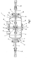
- FIG. 1 is a vacuum measuring container 1 illustrated, from the supply lines 2, 3 of a FIG. 2 apparent, in the interior 4 of the vacuum measuring container 1 arranged test pieces 5 protrude.
- the test piece 5 is eg a fluid coupling 6, by which the two supply lines 2, 3 are interconnected.
- the fluid coupling 6 is in FIG. 2 only schematically and largely symbolically illustrated. It consists of at the ends of the supply line 2, 3 arranged or formed flanges 7, 8, which are held together by axial pressure.
- the axial pressure is formed by an outer, the flanges 7, 8 in a stepped bore receiving coupling body 9 and a clamping bracket 11 which compresses the bottle 7, 8 via a pressure piece and is held by bolts on the coupling body 9.
- the vacuum measuring container 1 has a first housing part 12 and a second housing part 13, which are preferably mirror-symmetrical to one another and are designed to be identical to one another.
- the description of the housing part 12 is therefore based on the same reference numerals corresponding to the description of the housing part 13 and the components associated with it.
- the housing part 12 is formed substantially hollow cylindrical and closed at one end by a curved bottom 14. At the side facing the respective other housing part, the housing part 12 is provided with a flange 15 which has an annular end face 16 on the face side. Between the flanges 15 of the two housing parts 12, 13 an annular sealing element 17 is arranged. This preferably has a circular cross-section and is elastically yielding. Concentric with the sealing element 17, which bears against the plane surfaces 16, is a Outer ring 18 is arranged, which is supported with corresponding annular planar surfaces on the flat surfaces 16 and thereby limits the maximum compression of the sealing element 17.
- Out FIG. 1 apparent clamping claws 19, 20, 21 are arranged around the outer periphery of the flanges 15 around and clamp them against each other. Each clamping claw 19, 20, 21 has two parallel adjustable clamping fingers 22, 23, which surround the flange 15 outside and are to be clamped by means of a clamping screw against each other.
- each housing part 12, 13 provided with nozzles 24, 25, 26, 27, 28, 29, which can serve as a pump or measuring nozzle and connected to the measuring apparatus or, if there is no need, also simply sealed.
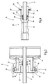
- the housing part 12 is provided at its bottom 14 with a housing passage 31 through which the supply line 2 extends.
- To the housing passage 31 includes a coaxial with the housing part 12 arranged, designed in the manner of a nozzle flange 32, which, in particular FIG. 3 can recognize, at its front end a flat annular surface 33 has.
- the section of the flange 32 extending in the radial direction is preferably provided with a conical surface 34.
- the flange 32 is materially connected to the bottom 14, for example, welded or soldered.
- the housing passage 31 further includes an adapter 35 which is approximately tubular formed and provided at one end with a radial flange 36. This has, on its side facing the flange 32 on a planar annular surface 37 which an annular sealing member 38 against the annular surface 33 presses.
- the sealing element 38 is, for example, an elastomer seal in the form of an O-ring, ie a rubber ring with a circular cross-section. This is arranged concentrically to the flange 32 as well as to the adapter 36.
- the adapter 36 has on its side facing the annular surface 37 a conical surface 39 on which, as on the conical surface 34, a clamping device 41 engages. This is designed in the manner of a cuff and, for example FIG.
- the second housing feedthrough is identical to the first housing feedthrough 31 and is therefore in FIG. 2 with the same, to distinguish only with an apostrophe marked, provided reference numerals.
- a support ring 43 Concentric with the sealing element 38, a support ring 43 is provided, which has mutually parallel, annular contact surfaces 44, 45, which are supported on the annular surfaces 33, 37. Externally, the support ring 43 engages over the edges of the flange 32 and the radial flange 37. It thus has a total of approximately T-shaped cross section and serves for centering of the adapter 35th
- the adapter 35 further comprises an approximately tubular, inwardly directed extension 46 which surrounds a stepped bore. Within the smaller diameter portion of the stepped bore, two annular grooves 47, 48 are formed in which O-rings 51, 52 or other sealing elements are seated. These seal at the outer Lateral surface of the line 2 extending with a small clearance through the stepped bore. The O-rings 51, 52 are compressed in the radial direction. So they tolerate minor wobbling movements of the supply line 2 or misalignment thereof without leaks. Only this measure enables safe isolation of the test object from the environment under practical test conditions.
- FIG. 4 illustrates an external adapter 54 connected to the supply line 2 and connected to the external adapter 55 (FIG. FIG. 1 ) and how it is used to connect the test piece 5 to an outer CO 2 -assedes system.
- the following description of the outer adapter 54 based FIG. 4 applies accordingly to the adapter 55.
- the outer adapters 54, 55 are spaced from the adapters 36, 36 'and supported only by the lines 2, 3. The connection to the vacuum measuring container thus exists exclusively via the lines 2, 3.
- a first sealing portion 56 is then formed with a cylindrical lateral surface. This is followed by an externally threaded portion 57 connects.
- a sleeve 458 is screwed, which is substantially tubular and is provided at its distal end of the sealing portion 56 with a radial flange 59. At its opposite end, it is internally provided with an annular groove 61 in which an O-ring 62 or other sealing element for sealing the sleeve 58 against the outer surface of the supply line 2 is arranged.
- To the outer adapter 54 also includes a coupling piece 63 which encloses a passage 64. This is part of a stepped through-hole whose diameter larger portion 65, the sleeve 58 at least up to its radial flange 59 and another sealing element, for example in the form of an O-ring 66, receives. This is based on the one hand on the end face of the sleeve 58 to the other on the opposite step surface of the stepped bore and on the inner peripheral surface of the stepped bore and on the outer peripheral surface of the portion 56 from.
- the coupling piece 63 is provided with a radial flange 67 in which an axially opening annular groove is provided with an annular sealing element, e.g. an O-ring 68 is provided.
- the radial flanges 59, 67 are stretched axially against each other by a not further illustrated clamping means.
- the vacuum measuring container 1 described so far operates as follows:
- test object 5 If the test object 5 is to be measured with regard to its leakage, first the ends of the supply lines 2, 3 are provided with the corresponding surfaces and threads. Then, the fluid coupling 6 is assembled and the test piece 5 is inserted with its leads 2, 3 through the fully open flanges 32 of the not yet connected housing parts 12, 13. Previously, the sealing member 17 and the outer ring 18 were passed over the specimen 5. It can now the housing parts 12, 13 joined together and the clamps 19, 20, 21 attached and tightened. In the next step, if this has not already been done, the sealing elements 38, the support rings 43 and the adapter 35 can be pushed onto the leads 2, 3, wherein the adapter 35 into the flanges 32 inside be pushed. Lying on both flanges 32, the corresponding sealing elements 38 and to these the radial flanges 36, respectively, the clamping device 41 can be placed and pulled tight.
- the specimen 5 is characterized not only sealed to the outside but also mechanically stored.
- the outer adapters 54, 55 are attached.
- the sleeve 58 is screwed onto the respective end of the supply line 2 or 3.
- the coupling piece 63 is attached by this is pushed over the sleeve 58 until the radial flange 67 abuts almost on the radial flange 59.
- both flanges are clamped against each other.
- the assembly is thus completed. It is now possible to connect the sockets 24 to 29 to the measuring device and the coupling pieces 63 to the corresponding CO 2 -leading system and the measurement can be carried out.
- the present on the vacuum tank 1 sealing elements are shielded both to the housing separating joint and to the adapters 31 and to the outer adapters 54, 55 each to the outside.
- the shielding is effected in each case by outer rings or, at least in the case of the adapters 54, 55, by narrow-gap adjoining parts of the respective adapter.
- at no point is the O-ring 68 exposed to the outside atmosphere over a large area.
- a vacuum container 1 For measuring CO 2 leaks to DUTs 5, a vacuum container 1 is provided, which is provided at two opposite ends with housing bushings 31, can be passed through the leads 2, 3 of the specimen 5 to the outside. At the housing passages adapter 35 are arranged, which allow an adaptation of the bushings 31 to different specimens.
- the measuring device also includes external adapters 54, 55 for connecting the test object to a CO 2 -conducting system.
Landscapes
- Physics & Mathematics (AREA)
- General Physics & Mathematics (AREA)
- Examining Or Testing Airtightness (AREA)
- Gasket Seals (AREA)
Claims (18)
- Récipient à vide pour mesurer (1), pour la mesure en particulier de fuites de CO2 sur des échantillons (5),
avec une première partie de boîtier (12) et avec une deuxième partie de boîtier (13), reliées ensemble de façon désolidarisable et étanche en étant placées l'une contre l'autre sur un joint de séparation,
avec un premier passage de boîtier (31), présentant un adaptateur (35) avec un dispositif d'étanchéité (51, 52, 38) pour l'échantillon,
avec un deuxième passage de boîtier (31'), présentant un adaptateur (35') avec un dispositif d'étanchéité (51', 52', 38') pour l'échantillon (5, 2, 3),
avec un adaptateur extérieur (55) supplémentaire, pour le raccordement d'une autre extrémité de l'échantillon (5) au système de fluide. - Récipient à vide pour mesurer selon la revendication 1, caractérisé en ce que les deux passages de boîtier (31, 31') sont disposés à l'opposé l'un de l'autre, de préférence coaxialement l'un à l'autre.
- Récipient à vide pour mesurer selon la revendication 1, caractérisé en ce que le premier passage de boîtier (31) est réalisé sur la première partie de boîtier (12) et le deuxième passage de boîtier (31') est réalisé sur la deuxième partie de boîtier (13).
- Récipient à vide pour mesurer selon la revendication 1, caractérisé en ce que le passage de boîtier (31, 31') comprend une bride (32, 32') reliée rigidement à la partie de boîtier (12, 13), et un adaptateur (35, 35') remplaçable, appliqué sur la bride (32, 32') et relié de façon désolidarisable à celle-ci, et portant un joint d'étanchéité (51, 52) adapté à l'échantillon (5, 2, 3).
- Récipient à vide pour mesurer selon la revendication 4, caractérisé en ce que l'adaptateur (35, 35') présente un perçage traversant, dont le diamètre n'est que légèrement plus grand que le diamètre extérieur d'une conduite d'alimentation (2, 3) appartenant à l'échantillon (5, 2, 3) .
- Récipient à vide pour mesurer selon la revendication 5,' caractérisé en ce que le perçage traversant présente au moins une gorge annulaire (47, 48, 47', 48') pour recevoir un élément d'étanchéité (51, 52, 51', 52'), pour isoler de façon étanche par rapport à la conduite d'alimentation (2, 3).
- Récipient à vide pour mesurer selon la revendication 4, caractérisé en ce que la bride (32) et l'adaptateur (35) présentent chacun une face annulaire (33, 67), de préférence plane, faces entre lesquelles un élément d'étanchéité (38) est susceptible d'être bloqué par serrage, avec effet d'étanchéité.
- Récipient à vide pour mesurer selon la revendication 7, caractérisé en ce que l'élément d'étanchéité (38) est une bague d'étanchéité déformable élastiquement, à laquelle est associée une bague de soutien extérieure (43), de préférence plus rigide, disposée concentriquement par rapport à la bague d'étanchéité, qui présente des faces d'appui (44, 45) à forme annulaire pour les faces annulaires (33, 37).
- Récipient à vide pour mesurer selon la revendication 7, caractérisé en ce que l'élément d'étanchéité (38) présente une section transversale circulaire.
- Récipient à vide pour mesurer selon la revendication 8, caractérisé en ce que la bague de soutien extérieure (43) rigide présente une section transversale en T.
- Récipient à vide pour mesurer selon la revendication 4, caractérisé en ce qu'au passage de boîtier (31) appartient un dispositif de serrage (41), à l'aide duquel l'adaptateur (35) est susceptible d'être serré contre la bride (32).
- Récipient à vide pour mesurer selon la revendication 1, caractérisé en ce qu'à l'adaptateur extérieur (54) appartient un manchon (58), assuré, de façon indéplaçable axialement, sur une extrémité d'une conduite d'amenée (2), passant à travers le passage de boîtier (31), de l'échantillon et portant un joint d'étanchéité (62), pour assurer une étanchéité par rapport à la conduite d'étanchéité (2).
- Récipient à vide pour mesurer selon la revendication 12, caractérisé en ce que le manchon (58) est un manchon vissé.
- Récipient à vide pour mesurer selon la revendication 12, caractérisé en ce que le manchon (58) présente, dans la paroi de son perçage traversant, une gorge annulaire (61), pour recevoir un élément d'étanchéité (62).
- Récipient à vide pour mesurer selon la revendication 12, caractérisé en ce que le manchon (58) porte une bride radiale (59).
- Récipient à vide pour mesurer selon la revendication 12, caractérisé en ce qu'à l'adaptateur extérieur (54) appartient une pièce de couplage (63), présentant un perçage traversant échelonné, servant de canal de passage (64) et recevant le manchon (58).
- Récipient à vide pour mesurer selon la revendication 16, caractérisé en ce qu'un élément d'étanchéité (66), coopérant avec la face extérieure de la conduite d'amenée (2), est disposé dans le perçage traversant.
- Récipient à vide pour mesurer selon la revendication 16, caractérisé en ce que la pièce de couplage (63) est munie d'une bride radiale (67), et en ce qu'une bague d'étanchéité (68) est disposée entrée la bride radiale (67) de la pièce de couplage (63) et la bride radiale (59) du manchon (58).
Applications Claiming Priority (2)
| Application Number | Priority Date | Filing Date | Title |
|---|---|---|---|
| DE2003154301 DE10354301B3 (de) | 2003-11-20 | 2003-11-20 | Vakuummessbehälter |
| DE10354301 | 2003-11-20 |
Publications (3)
| Publication Number | Publication Date |
|---|---|
| EP1533603A2 EP1533603A2 (fr) | 2005-05-25 |
| EP1533603A3 EP1533603A3 (fr) | 2008-01-30 |
| EP1533603B1 true EP1533603B1 (fr) | 2009-01-21 |
Family
ID=34428831
Family Applications (1)
| Application Number | Title | Priority Date | Filing Date |
|---|---|---|---|
| EP20040027395 Expired - Lifetime EP1533603B1 (fr) | 2003-11-20 | 2004-11-18 | Récipient à vide pour mesurer |
Country Status (2)
| Country | Link |
|---|---|
| EP (1) | EP1533603B1 (fr) |
| DE (2) | DE10354301B3 (fr) |
Families Citing this family (1)
| Publication number | Priority date | Publication date | Assignee | Title |
|---|---|---|---|---|
| CN103604569B (zh) * | 2013-11-04 | 2017-02-08 | 北京卫星环境工程研究所 | 直管氦质谱检漏的快速连接装置 |
Family Cites Families (7)
| Publication number | Priority date | Publication date | Assignee | Title |
|---|---|---|---|---|
| US2888331A (en) * | 1954-12-27 | 1959-05-26 | Virginia C Carpenter | Testing device |
| US4584877A (en) * | 1984-06-07 | 1986-04-29 | Semyon Brayman | Method and fixture for leak detection |
| US4766765A (en) * | 1986-11-13 | 1988-08-30 | Westinghouse Electric Corp. | Multiphase valve testing |
| FR2666654B1 (fr) * | 1990-09-12 | 1994-12-23 | Cit Alcatel | Dispositif de controle d'etancheite d'une piece. |
| DE4335894A1 (de) * | 1993-10-21 | 1995-04-27 | Leybold Ag | Verfahren zur Untersuchung der Eigenschaften eines Prüflings mit einem Hohlraum sowie für die Durchführung dieses Verfahrens geeignete Einrichtung |
| US5375456A (en) * | 1993-11-18 | 1994-12-27 | Trw Vehicle Safety Systems Inc. | Leak testing apparatus and method |
| ES2211242B1 (es) * | 2001-02-26 | 2005-05-01 | Frape Behr S.A. | Detector de defectos de estanqueidad, procedimientos, utilizacion e intercambiadores de calor correspondientes. |
-
2003
- 2003-11-20 DE DE2003154301 patent/DE10354301B3/de not_active Expired - Fee Related
-
2004
- 2004-11-18 EP EP20040027395 patent/EP1533603B1/fr not_active Expired - Lifetime
- 2004-11-18 DE DE200450008903 patent/DE502004008903D1/de not_active Expired - Lifetime
Also Published As
| Publication number | Publication date |
|---|---|
| EP1533603A2 (fr) | 2005-05-25 |
| EP1533603A3 (fr) | 2008-01-30 |
| DE502004008903D1 (de) | 2009-03-12 |
| DE10354301B3 (de) | 2005-08-18 |
Similar Documents
| Publication | Publication Date | Title |
|---|---|---|
| DE69620211T2 (de) | Vorrichtung zur erfassung von leckagen in rohrflanschverbindungen | |
| DE69104805T2 (de) | Vorrichtung zur Prüfung der Dichtigkeit eines Stückes. | |
| EP0237931B1 (fr) | Appareil pour examiner l'étanchéité des joints aux gaz, entre des pièces de tuyaux | |
| DE102016115398B4 (de) | Verfahren und Vorrichtung zur Prüfung von Faltenbälgen | |
| EP0064653B1 (fr) | Dispositif de fermeture pour conduites de gaz | |
| DE102017206533A1 (de) | Quetschventil und Verfahren zum Betreiben eines Quetschventils | |
| EP1533603B1 (fr) | Récipient à vide pour mesurer | |
| DE102016005301A1 (de) | Verbindungsvorrichtung, insbesondere in Form einer Schlauchkupplung | |
| DE102017006063A1 (de) | Prüfvorrichtung zum Ermitteln der Partikelbelastung von unter einem hohen Druck stehendem Wasserstoff | |
| DE3416109A1 (de) | Einrichtung zur schwenk- und loesbaren verbindung zweier winkelig zueinander verlaufenden rohrleitungen | |
| DE68924284T2 (de) | Säule für Hochdruck-Flüssigkeitschromatographie. | |
| EP0915191B1 (fr) | Appareillage pour faire un joint à vide entre deux corps en matériaux différents | |
| DE29600241U1 (de) | Lösbare Rohrverbindung für Kunststoffrohre | |
| DE4324401C1 (de) | Vorrichtung zur Prüfung von Gasleitungen | |
| CH626971A5 (en) | Device for the sealed locking of standardised interchangeable glass or quartz taper-ground joints usable in laboratories | |
| DE9203042U1 (de) | Mauerdurchführung | |
| EP4409258B1 (fr) | Technique d'essai pour un échantillon d'essai tubulaire faisant intervenir une pression de liquide | |
| DE102025100994A1 (de) | Dichtung; Vorrichtung, System und Verfahren zur Lecklokalisierung an einem Verbindungsstück, insbesondere an einer Schlauchverbindung oder einer Rohrverbindung, sowie deren jeweilige Verwendung | |
| DE3138355A1 (de) | Armatur fuer ein aus zwei metallrohren bestehendes leitungsrohr | |
| DE965863C (de) | Rohrverbinder | |
| DE3706216A1 (de) | Durch fluiddruck anbringbarer rohrverbinder | |
| DE10126210A1 (de) | Lösbare Kupplung für Rohrleitungen | |
| DE4309450A1 (en) | Leak testing device for pressurised lines, esp. for gas - has pre-testing and main testing devices, water container with column indicator, air pump, and couplings with automatic valves | |
| DE102023003222A1 (de) | Kopplungsmodul zur Kopplung mindestens eines Messinstruments und Vorrichtung sowie Verfahren zur Untersuchung einer Verbindung | |
| DE202015106855U1 (de) | Adapter, Blase und Prüfanordnung zur Rohrinspektion |
Legal Events
| Date | Code | Title | Description |
|---|---|---|---|
| PUAI | Public reference made under article 153(3) epc to a published international application that has entered the european phase |
Free format text: ORIGINAL CODE: 0009012 |
|
| AK | Designated contracting states |
Kind code of ref document: A2 Designated state(s): AT BE BG CH CY CZ DE DK EE ES FI FR GB GR HU IE IS IT LI LU MC NL PL PT RO SE SI SK TR |
|
| AX | Request for extension of the european patent |
Extension state: AL HR LT LV MK YU |
|
| PUAL | Search report despatched |
Free format text: ORIGINAL CODE: 0009013 |
|
| AK | Designated contracting states |
Kind code of ref document: A3 Designated state(s): AT BE BG CH CY CZ DE DK EE ES FI FR GB GR HU IE IS IT LI LU MC NL PL PT RO SE SI SK TR |
|
| AX | Request for extension of the european patent |
Extension state: AL HR LT LV MK YU |
|
| RIC1 | Information provided on ipc code assigned before grant |
Ipc: G01M 3/26 20060101AFI20050301BHEP Ipc: G01M 3/02 20060101ALI20071227BHEP |
|
| 17P | Request for examination filed |
Effective date: 20080318 |
|
| GRAP | Despatch of communication of intention to grant a patent |
Free format text: ORIGINAL CODE: EPIDOSNIGR1 |
|
| GRAS | Grant fee paid |
Free format text: ORIGINAL CODE: EPIDOSNIGR3 |
|
| AKX | Designation fees paid |
Designated state(s): DE ES FR GB IT SE |
|
| GRAA | (expected) grant |
Free format text: ORIGINAL CODE: 0009210 |
|
| AK | Designated contracting states |
Kind code of ref document: B1 Designated state(s): DE ES FR GB IT SE |
|
| REG | Reference to a national code |
Ref country code: GB Ref legal event code: FG4D Free format text: NOT ENGLISH |
|
| REF | Corresponds to: |
Ref document number: 502004008903 Country of ref document: DE Date of ref document: 20090312 Kind code of ref document: P |
|
| PG25 | Lapsed in a contracting state [announced via postgrant information from national office to epo] |
Ref country code: ES Free format text: LAPSE BECAUSE OF FAILURE TO SUBMIT A TRANSLATION OF THE DESCRIPTION OR TO PAY THE FEE WITHIN THE PRESCRIBED TIME-LIMIT Effective date: 20090502 |
|
| PG25 | Lapsed in a contracting state [announced via postgrant information from national office to epo] |
Ref country code: SE Free format text: LAPSE BECAUSE OF FAILURE TO SUBMIT A TRANSLATION OF THE DESCRIPTION OR TO PAY THE FEE WITHIN THE PRESCRIBED TIME-LIMIT Effective date: 20090421 |
|
| PLBE | No opposition filed within time limit |
Free format text: ORIGINAL CODE: 0009261 |
|
| STAA | Information on the status of an ep patent application or granted ep patent |
Free format text: STATUS: NO OPPOSITION FILED WITHIN TIME LIMIT |
|
| 26N | No opposition filed |
Effective date: 20091022 |
|
| PGFP | Annual fee paid to national office [announced via postgrant information from national office to epo] |
Ref country code: FR Payment date: 20101109 Year of fee payment: 7 |
|
| PGFP | Annual fee paid to national office [announced via postgrant information from national office to epo] |
Ref country code: DE Payment date: 20101130 Year of fee payment: 7 |
|
| PG25 | Lapsed in a contracting state [announced via postgrant information from national office to epo] |
Ref country code: IT Free format text: LAPSE BECAUSE OF FAILURE TO SUBMIT A TRANSLATION OF THE DESCRIPTION OR TO PAY THE FEE WITHIN THE PRESCRIBED TIME-LIMIT Effective date: 20090121 |
|
| PGFP | Annual fee paid to national office [announced via postgrant information from national office to epo] |
Ref country code: GB Payment date: 20101022 Year of fee payment: 7 |
|
| GBPC | Gb: european patent ceased through non-payment of renewal fee |
Effective date: 20111118 |
|
| REG | Reference to a national code |
Ref country code: FR Ref legal event code: ST Effective date: 20120731 |
|
| REG | Reference to a national code |
Ref country code: DE Ref legal event code: R119 Ref document number: 502004008903 Country of ref document: DE Effective date: 20120601 |
|
| PG25 | Lapsed in a contracting state [announced via postgrant information from national office to epo] |
Ref country code: GB Free format text: LAPSE BECAUSE OF NON-PAYMENT OF DUE FEES Effective date: 20111118 |
|
| PG25 | Lapsed in a contracting state [announced via postgrant information from national office to epo] |
Ref country code: FR Free format text: LAPSE BECAUSE OF NON-PAYMENT OF DUE FEES Effective date: 20111130 |
|
| PG25 | Lapsed in a contracting state [announced via postgrant information from national office to epo] |
Ref country code: DE Free format text: LAPSE BECAUSE OF NON-PAYMENT OF DUE FEES Effective date: 20120601 |