EP1533620A1 - Système et procédé de determination d'au moins un paramètre d'au moins un organe tournant au moyen d'un signal de position absolue - Google Patents
Système et procédé de determination d'au moins un paramètre d'au moins un organe tournant au moyen d'un signal de position absolue Download PDFInfo
- Publication number
- EP1533620A1 EP1533620A1 EP04292638A EP04292638A EP1533620A1 EP 1533620 A1 EP1533620 A1 EP 1533620A1 EP 04292638 A EP04292638 A EP 04292638A EP 04292638 A EP04292638 A EP 04292638A EP 1533620 A1 EP1533620 A1 EP 1533620A1
- Authority
- EP
- European Patent Office
- Prior art keywords
- activation
- transponder
- encoder
- parameter
- signal
- Prior art date
- Legal status (The legal status is an assumption and is not a legal conclusion. Google has not performed a legal analysis and makes no representation as to the accuracy of the status listed.)
- Granted
Links
- 238000000034 method Methods 0.000 title claims abstract description 35
- 230000004913 activation Effects 0.000 claims abstract description 64
- 238000001514 detection method Methods 0.000 claims abstract description 43
- 230000005540 biological transmission Effects 0.000 claims abstract description 8
- 238000004891 communication Methods 0.000 claims description 21
- 230000005284 excitation Effects 0.000 claims description 9
- 238000005259 measurement Methods 0.000 claims description 7
- 238000005457 optimization Methods 0.000 claims description 7
- 210000000056 organ Anatomy 0.000 claims description 2
- 230000007704 transition Effects 0.000 claims description 2
- 230000001419 dependent effect Effects 0.000 claims 1
- 230000003287 optical effect Effects 0.000 description 3
- 230000003213 activating effect Effects 0.000 description 2
- 230000001960 triggered effect Effects 0.000 description 2
- JBRZTFJDHDCESZ-UHFFFAOYSA-N AsGa Chemical compound [As]#[Ga] JBRZTFJDHDCESZ-UHFFFAOYSA-N 0.000 description 1
- 229910017214 AsGa Inorganic materials 0.000 description 1
- 230000005355 Hall effect Effects 0.000 description 1
- XUIMIQQOPSSXEZ-UHFFFAOYSA-N Silicon Chemical compound [Si] XUIMIQQOPSSXEZ-UHFFFAOYSA-N 0.000 description 1
- 230000009471 action Effects 0.000 description 1
- 230000000712 assembly Effects 0.000 description 1
- 238000000429 assembly Methods 0.000 description 1
- 238000013475 authorization Methods 0.000 description 1
- 230000005611 electricity Effects 0.000 description 1
- 238000005516 engineering process Methods 0.000 description 1
- 239000011521 glass Substances 0.000 description 1
- 230000010354 integration Effects 0.000 description 1
- 239000002184 metal Substances 0.000 description 1
- 230000005405 multipole Effects 0.000 description 1
- 230000000737 periodic effect Effects 0.000 description 1
- 239000000523 sample Substances 0.000 description 1
- 229910052710 silicon Inorganic materials 0.000 description 1
- 239000010703 silicon Substances 0.000 description 1
- 239000000758 substrate Substances 0.000 description 1
Images
Classifications
-
- B—PERFORMING OPERATIONS; TRANSPORTING
- B60—VEHICLES IN GENERAL
- B60C—VEHICLE TYRES; TYRE INFLATION; TYRE CHANGING; CONNECTING VALVES TO INFLATABLE ELASTIC BODIES IN GENERAL; DEVICES OR ARRANGEMENTS RELATED TO TYRES
- B60C23/00—Devices for measuring, signalling, controlling, or distributing tyre pressure or temperature, specially adapted for mounting on vehicles; Arrangement of tyre inflating devices on vehicles, e.g. of pumps or of tanks; Tyre cooling arrangements
- B60C23/02—Signalling devices actuated by tyre pressure
- B60C23/04—Signalling devices actuated by tyre pressure mounted on the wheel or tyre
- B60C23/0408—Signalling devices actuated by tyre pressure mounted on the wheel or tyre transmitting the signals by non-mechanical means from the wheel or tyre to a vehicle body mounted receiver
Definitions
- the invention relates to a system for determining at least one parameter of at least one rotating member with respect to a fixed structure, a method of determination of at least one such parameter as well as a motor vehicle including such a system.
- the invention typically applies to the determination of at least one parameter, such as the pressure, temperature, deformation and wear of a tire of motor vehicle.
- the antenna of the latter is positioned near the area of moving the transponder, typically in the wheel well.
- the detection device by activating the detection device, it is possible to obtain periodically the value of the parameter (s) measured by the transponder and make this value available to a system, for example security of the vehicle, who controls it and / or uses it.
- a problem that arises is the establishment of an activation procedure of the detection device which makes it possible to obtain a communication satisfactory between said device and the transponder. Indeed, the antenna with a given transmit / receive cone, activation must be performed when the transponder is in this cone.
- the invention proposes in particular a system of determination which makes it possible to synchronize the communication between the antenna and the transponder when it is in the cone transmission / reception, so as to secure communication by optimizing electricity consumption, while being able to adapt the frequency of communication to the operating conditions of the vehicle.
- the invention proposes a determination method of at least one parameter of at least one rotating member with respect to a fixed structure by means of such a system, in which the activation device compares the absolute position of the encoder to an activation position and, when the two positions are equal, said device activates or authorizes the activation of the detection device.
- the invention proposes a motor vehicle comprising such a system, each set being arranged so as to determine at least one parameter of a tire of said vehicle.
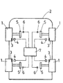
- the invention relates to a system for determining at least one parameter at least one rotating member 1 rotating relative to a fixed structure 2.
- this system is for determining at least one parameter of at least one tire 1 of a motor vehicle.
- the system allows the determination of the pressure, temperature, deformation and / or wear of all tires 1 of the vehicle.
- the system comprises, for each tire 1, a set comprising a transponder 3 able to measure the parameter (s) to determine, and a detection device 4 of the parameter (s) issued from the transponder 3.
- the transponder 3 is integral in rotation with the tire 1 and the detection device 4 is integral, in the vicinity of the transponder 3, the chassis 2 of the vehicle.
- the transponder 3 can be integral with the wheel or bearing on which the wheel is mounted.
- the determination system allows, by activating the detection device 4, periodically obtain the value of the parameter (s) measured by the transponder 3 and make this value available to a fixed system by relative to the chassis 2, for example vehicle safety, who controls it and / or used.
- the automatic determination of the parameter (s) may be used to warn the driver in the event of a fault.
- the Parameter (s) can be used in such driver assistance systems anti-lock wheels (ABS), trajectory control (ESP) or management assistance (DAE), so as to adapt the action of these systems according to the value of the determined parameters.
- the antenna is housed in the passage of the wheel on which is mounted the tire 1 and the transponder 3 is housed in the valve of the tire 1.
- the distance antenna - transponder 3 is reduced, which allows to optimize the electric power necessary for the communication of measurements between the tire 1 and the chassis 2.
- the transponder 3 is disposed in the tread of the tire 1, in particular to measure the deformation and wear of it.
- the assembly further comprises an encoder 5 integral in rotation with the tire 1 and a sensor 6 secured to the frame 2 of the vehicle.
- the encoder 5 and / or the sensor 6 can be arranged at the wheel bearing such that is for example described in document FR-2 700 588 issued by Applicant.
- the encoder 5 can in particular be secured in rotation to the rotating ring of the bearing and the sensor 6 can be associated with the fixed ring or dissociated from it, to be facing and reading distance from the encoder 5.
- encoder 5 The function of the encoder 5 is to deliver an angular position information of the tire 1 and a reference angular position information.
- encoder 5 includes a main track and a top-turn track, said top-turn track including a reference singularity which, as will be seen in the following of the description, is indexed with respect to the angular position of the transponder 3 on the tire 1.
- the encoder 5 is formed of a magnetic ring including on its surface the main track and the top-turn track which are concentric, said tracks comprising a succession of North poles and South, the reference singularity being achieved by a magnetic transition which is different from others.
- the senor 6 comprises an electronic circuit capable of delivering a signal representative of the angular position of the encoder 5 with respect to the frame 2 and a top-turn signal comprising a reference pulse corresponding to the detection of the reference singularity.
- the electronic circuit comprises means of resetting the position signal of the encoder 5 with respect to the position of the singularity, so as to deliver an absolute position signal of said encoder 5 by compared to the singularity, and therefore an absolute position signal of the tire 1 since the encoder 5 is integral in rotation with it.
- the senor 6 comprises at least three elements sensitive of which at least two are positioned opposite the main track and at least one is positioned next to the top-turn track.
- the sensitive elements are selected from the group including Hall effect probes, magnetoresistors, giant magnetoresistances.
- the sensor 6 used in this embodiment is capable of delivering two signals periodic electrical S1, S2 through quadrature elements sensed arranged opposite the main track and an electrical signal S3 by through the sensitive elements arranged next to the track top tower.
- sensors comprising two sensitive elements that are able to to deliver the signals S1 and S2 are also known.
- the electronic circuit is able to deliver digital position signals A, B squares in quadrature and a top turn signal C.
- the signals A, B being representative of the angular position of the encoder but also its speed of rotation as well as its direction of rotation.
- the electronic circuit further comprises a interpolator, for example of the type described in document FR-2 754 063 issued of the plaintiff, allowing to increase the resolution of the signals of exit.
- a resolution of the angular position of the encoder 5 less than 1 ° can be obtained.
- the sensor 6 can be integrated on a silicon substrate or equivalent by example AsGa, so as to form an integrated circuit and customized for a specific application, circuit sometimes referred to as ASIC to make reference to the integrated circuit designed partially or completely according to needs.
- the encoder 5 may be formed of a metal or glass target on which the tracks main and top tower have been engraved so as to form an optical pattern analogous to the multipole magnetic motif set out above, the elements Sensors are then formed of optical detectors.
- the electronic circuit comprises counting means able to determine, from an initial position, the variations of the angular position of the encoder 5.
- the counting means comprise a register in which the value of the angular position is incremented or decremented by an angular value corresponding to the number of fronts signals A and B which are detected, the initial value being for example fixed at zero when commissioning the system.
- the treatment device allows to know the relative position of the encoder 5 relative to the initial position.
- the electronic circuit makes it possible to readjust the relative angular position signal of the encoder 5 so as to obtain later and continuously, thanks to the means of counting, the absolute angular position signal of the encoder 5 relative to the position of the singularity.
- the system comprises an activation device 7, in the form of a computing unit, which is connected to each sensor 6 and to each detection device 4, so as to be able on the one hand to use the signal of absolute position and secondly activate each detection device 4 for collect the value of the parameter (s) detected.
- the activation device 7 is adapted, depending on the absolute position of the encoder, to activate the detection device 4 of a set when the transponder 3 of the assembly is in the transmission / reception cone of the antenna of said detection.
- the activation device 7 makes it possible to synchronize the passage of the transponder 3 in the cone with the activation of the detection device 4. Indeed, the position of the singularity being indexed with respect to that of the transponder 3, there is a known and constant shift between the absolute position signal and the position of the transponder 3. The angular range of the antenna transmit / receive cone being known, this shift is used by the activation device 7 for determine an activation position in which the transponder 3 is in said cone.
- the system according to the invention makes it possible, thanks to the synchronization, optimize the life of the battery powering device 7 and, if applicable, the battery supplying the transponder 3 in the case where it is active.
- each coder 5 comprises coding means of the pulse which are different from one encoder to the other, the activation device 7 comprising means for identifying the coding so as to activate the detection device 4 of the entire encoder 5 from which the pulse.
- the activation device 7 can simplify the wiring between the assemblies and the activation device 7, since the recognition of the tire 1 concerned does not depends more on the physical addressing of the position signals to the device 7.
- the coding means comprise a number of additional singularities that are distributed over the encoder 5.
- the activation device 7 compares the absolute position of the encoder 5 to the position determined activation and, when the two positions are equal, the device activates or authorizes the activation of the detection device 4 so as to allow the detection of the parameter (s).
- the activation device 7 When the activation device 7 authorizes the activation, it can be provided perform said activation at variable interrogation periods which are determined by the operating conditions of the tire.
- these conditions may be a function of the parameter (s) measured (pressure, temperature), vehicle running conditions such as that the speed or condition of the roadway (condition of rain or snow by example), positioning the tire 1 (front or rear).
- the activation device 7 is also powered with the relevant parameters and with the desired conditions, said device including means for delaying the activation when the latter is authorized.
- the activation position used may be equal to the indexed position of the transponder 3 relative to the reference singularity.
- the optimization procedure may involve analyzing the quality of the signal from the detection device 4, for example its signal-to-noise ratio, the rate communication error, the power communicated. If this quality is less than a first threshold, incrementing and / or decrementing by a given step, for example one degree, the activation position. Iteratively, the procedure allows, by analyzing the quality of the corresponding signal, to increment or decrement the activation position to obtain an activation position optimized in which the signal quality is maximum. This position Optimized is used later as a new activation position.
- the indexed position of the transponder 3 by reference to the reference singularity is previously stored in the activation device 7.
- this indexing is performed mechanically in the factory or in a workshop, on a bench capable of measuring the angular offset between the reference singularity and the transponder 3.
- the reference singularity is indexed relative to all the possible angular positions of the transponder 3 on the tire 1, these positions each corresponding to a mounting position possible of the wheel on the vehicle.
- the activation device 7 is able to activate the device 4 when each possible angular position of the transponder 3 is in the transmit / receive cone of the antenna. So for example for four possible positions, the detection device 4 will be activated four times, the communication being carried out satisfactorily only in one of the these positions.
- This embodiment allows, in case of assembly / disassembly of the wheel, not to have to re-index.
- the determination method comprises a prior procedure for indexing the position of the reference singularity by relative to the angular position of the transponder 3.
- This procedure can be performed by fixed frequency activation, for example every second, of the detection device 4 and, when the signal measured by the detection device 4 is satisfactory, determination and recording in the activation device 7 of the indexed position which is equal to the position 5.
- the quality the signal is analyzed to judge whether it is satisfactory.
- this procedure can be triggered at each commissioning of the determination system, before the determination of the parameter (s) according to the invention.
- a second threshold of signal quality is used in the activation device 7. if the signal quality is below the second threshold, indexing procedure instead of the optimization procedure.
- this embodiment allows, in case of power failure of the system when determining the parameter (s), to initiate a procedure indexing to reset the synchronization.
- this realization also allows to launch an indexing procedure in progress optimization.
Landscapes
- Engineering & Computer Science (AREA)
- Mechanical Engineering (AREA)
- Arrangements For Transmission Of Measured Signals (AREA)
- Measuring Fluid Pressure (AREA)
- Investigating Or Analysing Biological Materials (AREA)
- Transmission And Conversion Of Sensor Element Output (AREA)
- Measurement Of Length, Angles, Or The Like Using Electric Or Magnetic Means (AREA)
- Selective Calling Equipment (AREA)
Abstract
Description
- un transpondeur qui est solidaire en rotation du pneu, ledit transpondeur étant apte à mesurer le ou les paramètre(s) ; et
- un dispositif de détection du ou des paramètre(s) issu(s) du transpondeur, ledit dispositif étant solidaire du châssis du véhicule et comprenant une antenne apte à émettre un signal d'excitation au transpondeur et à recevoir la ou les mesure(s).
- un transpondeur solidaire en rotation de l'organe tournant, ledit transpondeur étant apte à mesurer le ou les paramètre(s) à déterminer ;
- un codeur solidaire en rotation de l'organe tournant, ledit codeur comprenant une piste principale et une piste top tour, ladite piste top tour comprenant une singularité de référence dont la position angulaire est indexée par rapport à la position angulaire du transpondeur sur l'organe tournant ;
- un capteur solidaire de la structure fixe, ledit capteur étant disposé en regard et à distance de lecture du codeur, ledit capteur comprenant un circuit électronique apte à délivrer un signal représentatif de la position angulaire du codeur par rapport à la structure fixe et un signal top tour comprenant une impulsion de référence correspondant à la détection de la singularité de référence, ledit circuit comprenant en outre des moyens de recalage du signal de position du codeur par rapport à la position de la singularité de sorte à délivrer un signal de position absolue dudit codeur par rapport à la singularité ;
- un dispositif de détection du ou des paramètre(s) issu(s) du transpondeur, ledit dispositif étant solidaire de la structure fixe et comprenant un moyen de communication apte à émettre un signal d'excitation au transpondeur et à recevoir la ou les mesure(s) ;
- un dispositif d'activation qui est connecté à chaque capteur et à chaque dispositif de détection, ledit dispositif d'activation étant apte, en fonction de la position absolue du codeur, à activer le dispositif de détection d'un ensemble lorsque le transpondeur de l'ensemble est dans le cône d'émission/réception du moyen de communication dudit dispositif de détection.
- le dispositif de détection 4 comprenant un moyen de communication, par exemple sous la forme d'une antenne directionnelle, apte à émettre un signal d'excitation, par exemple RF, au transpondeur 3 et à recevoir la ou les mesure(s) ; et
- le transpondeur 3 pouvant être de type actif ou de type passif suivant qu'il est alimenté par une batterie propre afin d'effectuer la mesure et la communication ou que ces fonctions sont induites par le signal d'excitation issu du dispositif de détection 4. Pour la détermination de la pression du pneu 1, le transpondeur 3 peut être du type à ondes acoustiques de surface (SAW).
- en dessous du seuil, l'activation soit réalisée à une fréquence fi ;
- au dessus du seuil, l'activation soit réalisée à une fréquence multiple de fi.
Claims (15)
- Système de détermination d'au moins un paramètre d'au moins un organe tournant (1) par rapport à une structure fixe (2), ledit système comprenant, pour chaque organe tournant (1), un ensemble comprenant :ledit système comprenant en outre :un transpondeur (3) solidaire en rotation de l'organe tournant (1), ledit transpondeur étant apte à mesurer le ou les paramètre(s) à déterminer ;un codeur (5) solidaire en rotation de l'organe tournant (1), ledit codeur comprenant une piste principale et une piste top tour, ladite piste top tour comprenant une singularité de référence dont la position angulaire est indexée par rapport à la position angulaire du transpondeur (3) sur l'organe tournant (1) ;un capteur (6) solidaire de la structure fixe (2), ledit capteur étant disposé en regard et à distance de lecture du codeur (5), ledit capteur comprenant un circuit électronique apte à délivrer un signal représentatif de la position angulaire du codeur (5) par rapport à la structure fixe (2) et un signal top tour comprenant une impulsion de référence correspondant à la détection de la singularité de référence, ledit circuit comprenant en outre des moyens de recalage du signal de position du codeur par rapport à la position de la singularité de sorte à délivrer un signal de position absolue dudit codeur (5) par rapport à la singularité ;un dispositif de détection (4) du ou des paramètre(s) issu(s) du transpondeur (3), ledit dispositif étant solidaire de la structure fixe (2) et comprenant un moyen de communication apte à émettre un signal d'excitation au transpondeur (3) et à recevoir la ou les mesure(s) ;un dispositif d'activation (7) qui est connecté à chaque capteur (6) et à chaque dispositif de détection (4), ledit dispositif d'activation étant apte, en fonction de la position absolue du codeur, à activer le dispositif de détection (4) d'un ensemble lorsque le transpondeur (3) de l'ensemble est dans le cône d'émission/réception du moyen de communication dudit dispositif de détection.
- Système selon la revendication 1, caractérisé en ce que le codeur (5) est formé d'un anneau magnétique comprenant sur sa surface la piste principale et la piste top tour qui sont concentriques, lesdites pistes comprenant une succession de pôles Nord et Sud, la singularité de référence étant réalisée par une transition magnétique qui est différente des autres.
- Système selon la revendications 1 ou 2, caractérisé en ce que la singularité de référence est indexée par rapport à toutes les positions angulaires possibles du transpondeur (3) sur l'organe tournant (1), le dispositif d'activation (7) étant apte à activer le dispositif de détection (4) lorsque chaque position angulaire possible du transpondeur (3) est dans le cône d'émission/réception du moyen de communication.
- Système selon l'une quelconque des revendications 1 à 3, caractérisé en ce que chaque codeur (5) comprend en outre des moyens de codage de l'impulsion qui sont différents d'un codeur (5) à l'autre, le dispositif d'activation (7) comprenant des moyens d'identification du codage de sorte à activer le dispositif de détection (4) de l'ensemble du codeur (5) dont est issue l'impulsion.
- Système selon la revendication 4, caractérisé en ce que les moyens de codage comprennent un nombre de singularités supplémentaires qui sont réparties sur le codeur (5).
- Procédé de détermination d'au moins un paramètre d'au moins un organe tournant (1) par rapport à une structure fixe (2) au moyen d'un système selon la revendication 1 ou 2, dans lequel le dispositif d'activation (7) compare la position absolue du codeur (5) à une position d'activation et, lorsque que les deux positions sont égales, ledit dispositif active ou autorise l'activation du dispositif de détection (4).
- Procédé selon la revendication 6, caractérisé en ce que la position d'activation est égale, au moins initialement, à la position indexée du transpondeur (3) par rapport à la singularité de référence.
- Procédé selon la revendication 6 ou 7, caractérisé en ce qu'il comprend une procédure itérative d'optimisation de la position d'activation dans laquelle la qualité du signal issu du dispositif de détection (4) est analysée, et, si la qualité est inférieure à un premier seuil, la position d'activation est incrémentée et/ou décrémentée d'un pas donné pour déterminer une nouvelle position optimisée qui est utilisée ultérieurement par le dispositif d'activation (7) en tant que nouvelle position d'activation.
- Procédé selon l'une quelconque des revendications 6 à 8, caractérisé en ce que, lorsque le dispositif d'activation (7) autorise l'activation, celle-ci est réalisée à des périodes d'interrogation variables qui sont déterminées en fonction de conditions de fonctionnement de l'organe tournant (1).
- Procédé selon l'une quelconque des revendications 6 à 9, caractérisé en ce que la position indexée du transpondeur (3) par rapport à la singularité de référence est préalablement mémorisée dans le dispositif d'activation (7).
- Procédé selon l'une quelconque des revendications 6 à 9, caractérisé en ce qu'il comprend une procédure préalable d'indexation de la position de la singularité de référence par rapport à la position angulaire du transpondeur (3) sur l'organe tournant (1).
- Procédé selon la revendication 11, caractérisé en ce que la procédure d'indexation est réalisée par activation à fréquence fixe du dispositif de détection (4), et, lorsque le signal mesuré par ledit dispositif est satisfaisant, détermination de la position indexée qui est égale à la position absolue du codeur (5).
- Procédé selon la revendication 11 ou 12 lorsqu'elle dépend de la revendication 8, dans lequel, si la qualité du signal est inférieure à un deuxième seuil qui est inférieur au premier seuil, la procédure d'indexation est réalisée à la place de la procédure d'optimisation.
- Véhicule automobile comprenant un système selon l'une quelconque des revendications 1 à 5, chaque ensemble étant disposé de sorte à déterminer au moins un paramètre d'un pneu (1) dudit véhicule.
- Véhicule selon la revendication 14, caractérisé en ce que le moyen de communication est logé dans le passage de la roue sur laquelle est monté le pneu (1) et en ce que le transpondeur (3) est logé dans la valve du pneu (1).
Applications Claiming Priority (2)
| Application Number | Priority Date | Filing Date | Title |
|---|---|---|---|
| FR0350880 | 2003-11-21 | ||
| FR0350880A FR2862752B1 (fr) | 2003-11-21 | 2003-11-21 | Systeme et procede de determination d'au moins un parametre d'au moins un organe tournant au moyen d'un signal de position absolue |
Publications (2)
| Publication Number | Publication Date |
|---|---|
| EP1533620A1 true EP1533620A1 (fr) | 2005-05-25 |
| EP1533620B1 EP1533620B1 (fr) | 2006-07-26 |
Family
ID=34430107
Family Applications (1)
| Application Number | Title | Priority Date | Filing Date |
|---|---|---|---|
| EP04292638A Expired - Lifetime EP1533620B1 (fr) | 2003-11-21 | 2004-11-08 | Système et procédé de determination d'au moins un paramètre d'au moins un organe tournant au moyen d'un signal de position absolue |
Country Status (6)
| Country | Link |
|---|---|
| US (1) | US7283925B2 (fr) |
| EP (1) | EP1533620B1 (fr) |
| JP (1) | JP2005158053A (fr) |
| AT (1) | ATE334400T1 (fr) |
| DE (1) | DE602004001658T2 (fr) |
| FR (1) | FR2862752B1 (fr) |
Cited By (1)
| Publication number | Priority date | Publication date | Assignee | Title |
|---|---|---|---|---|
| CN103883118A (zh) * | 2014-03-28 | 2014-06-25 | 交通运输部公路科学研究所 | 一种可测倾角变化的智能脚手架扣件 |
Families Citing this family (1)
| Publication number | Priority date | Publication date | Assignee | Title |
|---|---|---|---|---|
| CN105466333B (zh) * | 2015-12-22 | 2018-01-26 | 衢州职业技术学院 | 一种汽车转向同步角度测试装置 |
Citations (4)
| Publication number | Priority date | Publication date | Assignee | Title |
|---|---|---|---|---|
| DE4133999A1 (de) * | 1991-10-14 | 1993-04-22 | Rainer Achterholt | Vorrichtung zum messen und anzeigen des druckes in einem luftreifen, ventil und fernbedienungselement fuer eine solche vorrichtung |
| US5898301A (en) * | 1997-04-10 | 1999-04-27 | The Torrington Company | Magnetic encoder for producing an index signal |
| WO1999052722A1 (fr) * | 1998-04-13 | 1999-10-21 | Ssi Technologies, Inc. | Procede et appareil de detection de la pression du pneu d'une roue de vehicule |
| FR2832531A1 (fr) * | 2001-11-20 | 2003-05-23 | Siemens Vdo Automotive | Procede et dispositif de communication entre une roue de vehicule et un calculateur place dans ce vehicule |
Family Cites Families (8)
| Publication number | Priority date | Publication date | Assignee | Title |
|---|---|---|---|---|
| JPH0436613A (ja) * | 1990-06-01 | 1992-02-06 | Yamaha Corp | 磁気ロータリーエンコーダ |
| DE4100472C1 (fr) * | 1991-01-09 | 1992-07-23 | Texas Instruments Deutschland Gmbh, 8050 Freising, De | |
| EP0832765B1 (fr) * | 1996-09-27 | 2003-05-28 | Motorola, Inc. | Système de contrôle de la pression des pneus |
| US6362731B1 (en) * | 2000-12-06 | 2002-03-26 | Eaton Corporation | Tire pressure monitor and location identification system and method |
| US6683537B2 (en) * | 2001-03-29 | 2004-01-27 | The Goodyear Tire And Rubber Company | System of apparatus for monitoring a tire condition value in a pneumatic tire |
| JP4000891B2 (ja) * | 2002-04-12 | 2007-10-31 | トヨタ自動車株式会社 | タイヤ状態取得装置 |
| JP3975973B2 (ja) * | 2003-06-05 | 2007-09-12 | トヨタ自動車株式会社 | 車輪−車体間通信システム |
| US7104438B2 (en) * | 2003-10-22 | 2006-09-12 | The Goodyear Tire & Rubber Company | Method of integrating tire identification into a vehicle information system |
-
2003
- 2003-11-21 FR FR0350880A patent/FR2862752B1/fr not_active Expired - Fee Related
-
2004
- 2004-10-29 JP JP2004316879A patent/JP2005158053A/ja not_active Ceased
- 2004-11-08 AT AT04292638T patent/ATE334400T1/de not_active IP Right Cessation
- 2004-11-08 DE DE602004001658T patent/DE602004001658T2/de not_active Expired - Fee Related
- 2004-11-08 EP EP04292638A patent/EP1533620B1/fr not_active Expired - Lifetime
- 2004-11-12 US US10/986,279 patent/US7283925B2/en not_active Expired - Fee Related
Patent Citations (4)
| Publication number | Priority date | Publication date | Assignee | Title |
|---|---|---|---|---|
| DE4133999A1 (de) * | 1991-10-14 | 1993-04-22 | Rainer Achterholt | Vorrichtung zum messen und anzeigen des druckes in einem luftreifen, ventil und fernbedienungselement fuer eine solche vorrichtung |
| US5898301A (en) * | 1997-04-10 | 1999-04-27 | The Torrington Company | Magnetic encoder for producing an index signal |
| WO1999052722A1 (fr) * | 1998-04-13 | 1999-10-21 | Ssi Technologies, Inc. | Procede et appareil de detection de la pression du pneu d'une roue de vehicule |
| FR2832531A1 (fr) * | 2001-11-20 | 2003-05-23 | Siemens Vdo Automotive | Procede et dispositif de communication entre une roue de vehicule et un calculateur place dans ce vehicule |
Cited By (2)
| Publication number | Priority date | Publication date | Assignee | Title |
|---|---|---|---|---|
| CN103883118A (zh) * | 2014-03-28 | 2014-06-25 | 交通运输部公路科学研究所 | 一种可测倾角变化的智能脚手架扣件 |
| CN103883118B (zh) * | 2014-03-28 | 2016-05-18 | 交通运输部公路科学研究所 | 一种可测倾角变化的智能脚手架扣件 |
Also Published As
| Publication number | Publication date |
|---|---|
| US7283925B2 (en) | 2007-10-16 |
| ATE334400T1 (de) | 2006-08-15 |
| FR2862752B1 (fr) | 2006-02-17 |
| DE602004001658T2 (de) | 2007-07-19 |
| US20050110625A1 (en) | 2005-05-26 |
| FR2862752A1 (fr) | 2005-05-27 |
| EP1533620B1 (fr) | 2006-07-26 |
| DE602004001658D1 (de) | 2006-09-07 |
| JP2005158053A (ja) | 2005-06-16 |
Similar Documents
| Publication | Publication Date | Title |
|---|---|---|
| EP1593532B1 (fr) | Système de controle de la pression des pneumatiques des roues d'un véhicule automobile | |
| EP1167927A1 (fr) | Dispositif de détermination de la position angulaire absolue d'un organe tournant | |
| FR2924518A1 (fr) | Dispositif de localisation de la position droite et gauche d'un ensemble pneumatique et roue d'un vehicule | |
| EP1743151B1 (fr) | Roulement capteur de deformations comprenant quatre jauges de contraintes | |
| FR2856142A1 (fr) | Determination de la position angulaire absolue d'un volant par mesure incrementale et mesure de la vitesse differentielle des roues | |
| FR2845154A1 (fr) | Capteur d'angle absolu comprenant un codeur a singularites non-equireparties | |
| FR2879330A1 (fr) | Procede et dispositif de determination de l'etat de deplacement d'un vehicule | |
| FR2862382A1 (fr) | Systeme capteur de couple absolu de torsion et module le comprenant | |
| EP1533147A2 (fr) | Système et procédé de détermination d'au moins un paramêtre et d'au moins un organe tournant au moyen d'un signal de position | |
| FR2866269A1 (fr) | Dispositif et procede pour determiner la position laterale de roues | |
| EP1533148A1 (fr) | Système et procédé de determination d'au moins un paramètre d'au moins un organe tournant au moyen de signaux de réference et de vitesse | |
| EP1631793B1 (fr) | Determination de la position angulaire absolue d'un volant par discrimination de sequences binaires | |
| WO2017059938A1 (fr) | Unite electronique de roue et son procede de montage | |
| EP1533620B1 (fr) | Système et procédé de determination d'au moins un paramètre d'au moins un organe tournant au moyen d'un signal de position absolue | |
| EP1403621B1 (fr) | Capteur d'angle absolu | |
| EP1923669B1 (fr) | Procédé de datation d'une position angulaire remarquable d'un capteur porté par un pneumatique | |
| WO2019016455A1 (fr) | Procédé de localisation d'une position de chaque roue d'un véhicule automobile associée à un boîtier électronique | |
| FR2904412A1 (fr) | Procede de determination de deux signaux en quadrature | |
| FR2879750A1 (fr) | Procede de determination du sens de rotation d'une roue et dispositif mettant en oeuvre ce procede | |
| EP2307210A2 (fr) | Dispositif de localisation de la position droite et gauche d'un ensemble pneumatique et roue d'un vehicule | |
| FR2919415A1 (fr) | Procede et dispositif de localisation des roues d'un vehicule. | |
| FR3098294A1 (fr) | Dispositif de mesure de l’écartement de deux éléments d’un appareil tendeur d’une caténaire | |
| FR2856147A1 (fr) | Determination de la position angulaire absolue d'un volant par discrimination de sequences binaires | |
| WO2005121731A1 (fr) | Roulement capteur de deformations comprenant deux jauges de contraintes | |
| EP1882158B1 (fr) | Procede de discrimination d'une impulsion de reference |
Legal Events
| Date | Code | Title | Description |
|---|---|---|---|
| PUAI | Public reference made under article 153(3) epc to a published international application that has entered the european phase |
Free format text: ORIGINAL CODE: 0009012 |
|
| AK | Designated contracting states |
Kind code of ref document: A1 Designated state(s): AT BE BG CH CY CZ DE DK EE ES FI FR GB GR HU IE IS IT LI LU MC NL PL PT RO SE SI SK TR |
|
| AX | Request for extension of the european patent |
Extension state: AL HR LT LV MK YU |
|
| 17P | Request for examination filed |
Effective date: 20051025 |
|
| GRAP | Despatch of communication of intention to grant a patent |
Free format text: ORIGINAL CODE: EPIDOSNIGR1 |
|
| AKX | Designation fees paid |
Designated state(s): AT BE BG CH CY CZ DE DK EE ES FI FR GB GR HU IE IS IT LI LU MC NL PL PT RO SE SI SK TR |
|
| GRAS | Grant fee paid |
Free format text: ORIGINAL CODE: EPIDOSNIGR3 |
|
| GRAA | (expected) grant |
Free format text: ORIGINAL CODE: 0009210 |
|
| AK | Designated contracting states |
Kind code of ref document: B1 Designated state(s): AT BE BG CH CY CZ DE DK EE ES FI FR GB GR HU IE IS IT LI LU MC NL PL PT RO SE SI SK TR |
|
| PG25 | Lapsed in a contracting state [announced via postgrant information from national office to epo] |
Ref country code: SI Free format text: LAPSE BECAUSE OF FAILURE TO SUBMIT A TRANSLATION OF THE DESCRIPTION OR TO PAY THE FEE WITHIN THE PRESCRIBED TIME-LIMIT Effective date: 20060726 Ref country code: GB Free format text: LAPSE BECAUSE OF FAILURE TO SUBMIT A TRANSLATION OF THE DESCRIPTION OR TO PAY THE FEE WITHIN THE PRESCRIBED TIME-LIMIT Effective date: 20060726 Ref country code: IT Free format text: LAPSE BECAUSE OF FAILURE TO SUBMIT A TRANSLATION OF THE DESCRIPTION OR TO PAY THE FEE WITHIN THE PRESCRIBED TIME-LIMIT;WARNING: LAPSES OF ITALIAN PATENTS WITH EFFECTIVE DATE BEFORE 2007 MAY HAVE OCCURRED AT ANY TIME BEFORE 2007. THE CORRECT EFFECTIVE DATE MAY BE DIFFERENT FROM THE ONE RECORDED. Effective date: 20060726 Ref country code: SK Free format text: LAPSE BECAUSE OF FAILURE TO SUBMIT A TRANSLATION OF THE DESCRIPTION OR TO PAY THE FEE WITHIN THE PRESCRIBED TIME-LIMIT Effective date: 20060726 Ref country code: NL Free format text: LAPSE BECAUSE OF FAILURE TO SUBMIT A TRANSLATION OF THE DESCRIPTION OR TO PAY THE FEE WITHIN THE PRESCRIBED TIME-LIMIT Effective date: 20060726 Ref country code: AT Free format text: LAPSE BECAUSE OF FAILURE TO SUBMIT A TRANSLATION OF THE DESCRIPTION OR TO PAY THE FEE WITHIN THE PRESCRIBED TIME-LIMIT Effective date: 20060726 Ref country code: PL Free format text: LAPSE BECAUSE OF FAILURE TO SUBMIT A TRANSLATION OF THE DESCRIPTION OR TO PAY THE FEE WITHIN THE PRESCRIBED TIME-LIMIT Effective date: 20060726 Ref country code: IS Free format text: LAPSE BECAUSE OF FAILURE TO SUBMIT A TRANSLATION OF THE DESCRIPTION OR TO PAY THE FEE WITHIN THE PRESCRIBED TIME-LIMIT Effective date: 20060726 Ref country code: RO Free format text: LAPSE BECAUSE OF FAILURE TO SUBMIT A TRANSLATION OF THE DESCRIPTION OR TO PAY THE FEE WITHIN THE PRESCRIBED TIME-LIMIT Effective date: 20060726 Ref country code: CZ Free format text: LAPSE BECAUSE OF FAILURE TO SUBMIT A TRANSLATION OF THE DESCRIPTION OR TO PAY THE FEE WITHIN THE PRESCRIBED TIME-LIMIT Effective date: 20060726 Ref country code: FI Free format text: LAPSE BECAUSE OF FAILURE TO SUBMIT A TRANSLATION OF THE DESCRIPTION OR TO PAY THE FEE WITHIN THE PRESCRIBED TIME-LIMIT Effective date: 20060726 Ref country code: IE Free format text: LAPSE BECAUSE OF FAILURE TO SUBMIT A TRANSLATION OF THE DESCRIPTION OR TO PAY THE FEE WITHIN THE PRESCRIBED TIME-LIMIT Effective date: 20060726 |
|
| REG | Reference to a national code |
Ref country code: GB Ref legal event code: FG4D Free format text: NOT ENGLISH |
|
| REG | Reference to a national code |
Ref country code: CH Ref legal event code: EP |
|
| REG | Reference to a national code |
Ref country code: IE Ref legal event code: FG4D Free format text: LANGUAGE OF EP DOCUMENT: FRENCH |
|
| REF | Corresponds to: |
Ref document number: 602004001658 Country of ref document: DE Date of ref document: 20060907 Kind code of ref document: P |
|
| PG25 | Lapsed in a contracting state [announced via postgrant information from national office to epo] |
Ref country code: BG Free format text: LAPSE BECAUSE OF FAILURE TO SUBMIT A TRANSLATION OF THE DESCRIPTION OR TO PAY THE FEE WITHIN THE PRESCRIBED TIME-LIMIT Effective date: 20061026 Ref country code: SE Free format text: LAPSE BECAUSE OF FAILURE TO SUBMIT A TRANSLATION OF THE DESCRIPTION OR TO PAY THE FEE WITHIN THE PRESCRIBED TIME-LIMIT Effective date: 20061026 Ref country code: DK Free format text: LAPSE BECAUSE OF FAILURE TO SUBMIT A TRANSLATION OF THE DESCRIPTION OR TO PAY THE FEE WITHIN THE PRESCRIBED TIME-LIMIT Effective date: 20061026 |
|
| PG25 | Lapsed in a contracting state [announced via postgrant information from national office to epo] |
Ref country code: ES Free format text: LAPSE BECAUSE OF FAILURE TO SUBMIT A TRANSLATION OF THE DESCRIPTION OR TO PAY THE FEE WITHIN THE PRESCRIBED TIME-LIMIT Effective date: 20061106 |
|
| PG25 | Lapsed in a contracting state [announced via postgrant information from national office to epo] |
Ref country code: BE Free format text: LAPSE BECAUSE OF NON-PAYMENT OF DUE FEES Effective date: 20061130 Ref country code: MC Free format text: LAPSE BECAUSE OF NON-PAYMENT OF DUE FEES Effective date: 20061130 |
|
| PG25 | Lapsed in a contracting state [announced via postgrant information from national office to epo] |
Ref country code: PT Free format text: LAPSE BECAUSE OF FAILURE TO SUBMIT A TRANSLATION OF THE DESCRIPTION OR TO PAY THE FEE WITHIN THE PRESCRIBED TIME-LIMIT Effective date: 20061226 |
|
| NLV1 | Nl: lapsed or annulled due to failure to fulfill the requirements of art. 29p and 29m of the patents act | ||
| GBV | Gb: ep patent (uk) treated as always having been void in accordance with gb section 77(7)/1977 [no translation filed] |
Effective date: 20060726 |
|
| REG | Reference to a national code |
Ref country code: IE Ref legal event code: FD4D |
|
| PLBE | No opposition filed within time limit |
Free format text: ORIGINAL CODE: 0009261 |
|
| STAA | Information on the status of an ep patent application or granted ep patent |
Free format text: STATUS: NO OPPOSITION FILED WITHIN TIME LIMIT |
|
| 26N | No opposition filed |
Effective date: 20070427 |
|
| BERE | Be: lapsed |
Owner name: SNR ROULEMENTS Effective date: 20061130 |
|
| PG25 | Lapsed in a contracting state [announced via postgrant information from national office to epo] |
Ref country code: GR Free format text: LAPSE BECAUSE OF FAILURE TO SUBMIT A TRANSLATION OF THE DESCRIPTION OR TO PAY THE FEE WITHIN THE PRESCRIBED TIME-LIMIT Effective date: 20061027 |
|
| PG25 | Lapsed in a contracting state [announced via postgrant information from national office to epo] |
Ref country code: EE Free format text: LAPSE BECAUSE OF FAILURE TO SUBMIT A TRANSLATION OF THE DESCRIPTION OR TO PAY THE FEE WITHIN THE PRESCRIBED TIME-LIMIT Effective date: 20060726 |
|
| PG25 | Lapsed in a contracting state [announced via postgrant information from national office to epo] |
Ref country code: LU Free format text: LAPSE BECAUSE OF NON-PAYMENT OF DUE FEES Effective date: 20061108 Ref country code: TR Free format text: LAPSE BECAUSE OF FAILURE TO SUBMIT A TRANSLATION OF THE DESCRIPTION OR TO PAY THE FEE WITHIN THE PRESCRIBED TIME-LIMIT Effective date: 20060726 Ref country code: HU Free format text: LAPSE BECAUSE OF FAILURE TO SUBMIT A TRANSLATION OF THE DESCRIPTION OR TO PAY THE FEE WITHIN THE PRESCRIBED TIME-LIMIT Effective date: 20070127 |
|
| PG25 | Lapsed in a contracting state [announced via postgrant information from national office to epo] |
Ref country code: CY Free format text: LAPSE BECAUSE OF FAILURE TO SUBMIT A TRANSLATION OF THE DESCRIPTION OR TO PAY THE FEE WITHIN THE PRESCRIBED TIME-LIMIT Effective date: 20060726 |
|
| PGFP | Annual fee paid to national office [announced via postgrant information from national office to epo] |
Ref country code: DE Payment date: 20081114 Year of fee payment: 5 |
|
| REG | Reference to a national code |
Ref country code: CH Ref legal event code: PL |
|
| PG25 | Lapsed in a contracting state [announced via postgrant information from national office to epo] |
Ref country code: CH Free format text: LAPSE BECAUSE OF NON-PAYMENT OF DUE FEES Effective date: 20081130 Ref country code: LI Free format text: LAPSE BECAUSE OF NON-PAYMENT OF DUE FEES Effective date: 20081130 |
|
| PG25 | Lapsed in a contracting state [announced via postgrant information from national office to epo] |
Ref country code: DE Free format text: LAPSE BECAUSE OF NON-PAYMENT OF DUE FEES Effective date: 20100601 |
|
| REG | Reference to a national code |
Ref country code: FR Ref legal event code: PLFP Year of fee payment: 12 |
|
| REG | Reference to a national code |
Ref country code: FR Ref legal event code: PLFP Year of fee payment: 13 |
|
| PGFP | Annual fee paid to national office [announced via postgrant information from national office to epo] |
Ref country code: FR Payment date: 20161118 Year of fee payment: 13 |
|
| REG | Reference to a national code |
Ref country code: FR Ref legal event code: ST Effective date: 20180731 |
|
| PG25 | Lapsed in a contracting state [announced via postgrant information from national office to epo] |
Ref country code: FR Free format text: LAPSE BECAUSE OF NON-PAYMENT OF DUE FEES Effective date: 20171130 |