EP1533648A1 - Terminal de communication mobile protégé contre les chocs - Google Patents
Terminal de communication mobile protégé contre les chocs Download PDFInfo
- Publication number
- EP1533648A1 EP1533648A1 EP04090441A EP04090441A EP1533648A1 EP 1533648 A1 EP1533648 A1 EP 1533648A1 EP 04090441 A EP04090441 A EP 04090441A EP 04090441 A EP04090441 A EP 04090441A EP 1533648 A1 EP1533648 A1 EP 1533648A1
- Authority
- EP
- European Patent Office
- Prior art keywords
- display element
- mobile terminal
- terminal device
- receiving section
- case
- Prior art date
- Legal status (The legal status is an assumption and is not a legal conclusion. Google has not performed a legal analysis and makes no representation as to the accuracy of the status listed.)
- Granted
Links
- 239000000758 substrate Substances 0.000 claims abstract description 13
- 239000004973 liquid crystal related substance Substances 0.000 description 8
- 238000005452 bending Methods 0.000 description 6
- 238000007796 conventional method Methods 0.000 description 5
- 230000001681 protective effect Effects 0.000 description 3
- 238000004891 communication Methods 0.000 description 2
- 230000035939 shock Effects 0.000 description 2
- 230000005540 biological transmission Effects 0.000 description 1
- 230000007423 decrease Effects 0.000 description 1
- 230000002093 peripheral effect Effects 0.000 description 1
- 239000012780 transparent material Substances 0.000 description 1
- 239000013585 weight reducing agent Substances 0.000 description 1
Images



Classifications
-
- H—ELECTRICITY
- H04—ELECTRIC COMMUNICATION TECHNIQUE
- H04M—TELEPHONIC COMMUNICATION
- H04M1/00—Substation equipment, e.g. for use by subscribers
- H04M1/02—Constructional features of telephone sets
- H04M1/18—Telephone sets specially adapted for use in ships, mines, or other places exposed to adverse environment
-
- H—ELECTRICITY
- H04—ELECTRIC COMMUNICATION TECHNIQUE
- H04M—TELEPHONIC COMMUNICATION
- H04M1/00—Substation equipment, e.g. for use by subscribers
- H04M1/02—Constructional features of telephone sets
- H04M1/0202—Portable telephone sets, e.g. cordless phones, mobile phones or bar type handsets
- H04M1/0206—Portable telephones comprising a plurality of mechanically joined movable body parts, e.g. hinged housings
- H04M1/0208—Portable telephones comprising a plurality of mechanically joined movable body parts, e.g. hinged housings characterized by the relative motions of the body parts
- H04M1/0214—Foldable telephones, i.e. with body parts pivoting to an open position around an axis parallel to the plane they define in closed position
Definitions
- the present invention relates to a mobile terminal device.
- a mobile terminal device that has a display element protected against heavy impact occurring when the device is accidentally dropped, for example.
- Mobile terminal devices used for telephone conversation or transmission of various kinds of information such as mobile phones, personal handy-phone systems (PHSs) and personal digital assistants (PDAs), have been developed and widely used.
- PHSs personal handy-phone systems
- PDAs personal digital assistants
- Such mobile terminal devices have a display unit, such as a liquid crystal display (LCD), serving as a man/machine interface for displaying information being transmitted.
- a display unit such as a liquid crystal display (LCD)
- LCD liquid crystal display
- the display screen of the display unit is becoming larger and larger, enabling effective display of vast amounts of textual or graphical information (including photographs) acquired from a network, such as the Internet, or a host computer.
- an electronic device with a liquid crystal display whose frame, into which the display window of the liquid crystal display unit is fitted, and is designed having varying thickness to reduce breakage of the display unit even if the housing is bent by an external impact or pressing force for example, see Japanese Patent laid-open Publication No. 122037/2000, p.3, FIGS. 1 and 2).
- a portable information terminal device, a support structure for a flat panel display and an electronic device that have an internal shock absorbing mechanism to prevent breakage of the device subjected to a shock for example, see Japanese Patent laid-open Publication No. 175608/2001, p.2-3, FIGS. 1 and 2, and Japanese Patent laid-open Publication No.
- some mobile terminal devices such as mobile phones, are of a folding type.
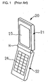
- conventional mobile phone 20 shown in FIG. 1 has receiving section 21 and transmitting section 22 connected to each other by hinge section H.
- Receiving section 21 has display section 23, such as a liquid crystal display panel, and transmitting section 22 has a plurality of key switches 24.
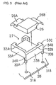
- receiving section 21 of mobile phone 20 typically comprises front case 25, display element 26, holder 27, substrate 28 and back case 29.
- Holder 27 is attached to substrate 28 and holds display element 26, such as a liquid crystal display panel, on the front side of mobile phone 20 (that is, on the opposite side of substrate 28).
- Front case 25 serves to protect display element 26, and at least a part thereof corresponding to the display area of display element 26 is made of a transparent material to allow a user to see the characters or graphics on the display area.
- holder 27 for fixedly holding display element 26 has a plurality of (two, for example) pins 30A and 30B on the back side thereof, and pins 30A and 30B are fitted into holes 31 A and 31 B formed in substrate 28.
- Holder 27, which has a substantially rectangular shape, has side walls 32A and 32B that extend along the periphery of display element 26 when holder 27 holds display element 26.
- Pins 30A and 30B described above are disposed at corners where side faces 33A to 33C of side walls 32A and 32B intersect with the bottom of holder 27 on which display element 26 is mounted.
- Display element 26 on the holder 27 is connected to a driving section (driver) on substrate 28 via flexible substrates 26A and 26B or the like.
- the conventional technique described above has various drawbacks. First,it is difficult to increase the display area. This is because the display element is inadequately protected. According to the conventional protective measure, the display element is protected by pins provided at the highly rigid peripheral part of the holder. However, if the display element is subjected to heavy impact when the folding portable terminal is dropped, for example, the portable terminal is deformed as shown in FIG. 2. The conventional technique, which takes no protective measure at the middle part of the holder, does not protect against increased bending of the display element due to increase of the display area, and thus, the display element may break.
- the invention has been devised in view of the problems with the conventional techniques described above, and an object is to provide a mobile terminal device that overcomes or eases the problems.
- mobile terminal devices According to attain the object, mobile terminal devices according to the invention have the following characteristics.
- a mobile terminal device comprises a transmitting section and a receiving section, the receiving section has a front case and a back case, and a display element, a holder and a substrate are housed in between the front case and the back case.
- the front case of the receiving section has a rib that is larger than the circumference of the display element and has a plurality of recesses.
- the mobile terminal device according to the invention described above has a remarkable practical advantage. That is, the display screen can be upsized, which is necessary for mobile terminal devices that transmit or receive a vast amount of data through the Internet or transmit or receive photographs taken with the built-in charge coupled device (CCD) camera. In addition, the mobile terminal device can be reduced in thickness, which contributes to weight reduction or the like, which is necessary for portable electronic devises.
- CCD charge coupled device
- At least some of the plurality of recesses may be shaped near corners of the display element.
- four recesses may be shaped near four corners of the display element.
- the transmitting section and the receiving secti may be capable of rotating about a hinge.
- a mobile terminal device may have a display element mounted thereon and a case that houses the display element and has a plurality of recesses along the circumference thereof.
- the plurality of recesses may be shaped at four corners of the case.
- the case may be rotatably connected to another case by a hinge.
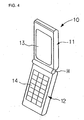
- mobile phone 10 comprises receiving section 11 and transmitting section 12 that are rotatably connected to each other by hinge H.
- Receiving section 11 has relatively large display unit 13, such as a liquid crystal display panel.
- transmitting section 12 has key switches 14. Therefore, viewed from the outside, mobile phone 10 is substantially the same as conventional mobile phone 10 shown in FIG. 1.
- receiving section 11 of mobile phone 10 comprises display element 16, holder 17, substrate 18, front case 15 and back case 19.
- display element 16, holder 17 and substrate 18 are housed in between front case 15 and back case 19 that are put together.
- receiving section 11 has an extensible antenna (not shown) and a speaker (not shown), and transmitting section 12 has a microphone (not shown).
- Display element 16 is disposed on front case 15 of receiving section 11 of mobile phone 10.
- Holder 17 is configured to cover the four side walls and the back surface of display element 16.
- Substrate 18 is mounted on holder 17.
- back case 19 of receiving section 11 is disposed on substrate 18.
- Front case 15 of receiving section 11 has seamless rib 15A on the periphery thereof.
- a plurality of recesses (notches) 15B are shaped in rib 15A.
- four recesses 15B are shaped near the four corners of display element 16, for example.
- Recesses 15B may have any shape that reduces the rigidity of rib 15 as required when an impact occurs and may be U-shaped or V-shaped, for example.
- phone 10 is opened by rotating receiving section 11 and transmitting section 12 mutually about hinge H. Then, the user enters the telephone number of a person he/she wants to talk with or communicate with by manipulating key switches 14 on transmitting section 12. Then, once a wireless communication link with a base station (not shown) is established via the antenna described above, the user speaks into the microphone on transmitting section 12 and hears the voice of the person on the other end of the link via the speaker on receiving section 11. Alternatively, in the case of communication via the Internet or the like, the textual or graphical data or information received is displayed on display element 16.
- display element 16 displays the entered number or the like so that the user can confirm the entry.
- receiving section 11 and transmitting section 12 are rotated about hinge H to be folded, thereby making mobile phone 10 compact and protecting the display area of display unit 13.
- Front case 15 of receiving section 11 in which display element 16 is disposed has an extremely reduced rigidity (that is, an extremely increased flexibility) at the plurality of recesses 15B shaped in rib 15A surrounding front case 15 of receiving section 11. Therefore, when mobile phone 10 is dropped and subjected to an impact, a great internal stress occurs at recesses 15B shaped in rib 15A surrounding front case 15 of receiving section 11. Thus, mobile phone 10 is adequately bent at recesses 15B as shown in FIG. 7. Thus, no great internal stress occurs in display element 16 in receiving section 11, so that bending of display element 16 itself is largely reduced.
Landscapes
- Engineering & Computer Science (AREA)
- Signal Processing (AREA)
- Telephone Set Structure (AREA)
- Liquid Crystal (AREA)
Applications Claiming Priority (2)
| Application Number | Priority Date | Filing Date | Title |
|---|---|---|---|
| JP2003388685A JP4461778B2 (ja) | 2003-11-19 | 2003-11-19 | 携帯端末機器 |
| JP2003388685 | 2003-11-19 |
Publications (2)
| Publication Number | Publication Date |
|---|---|
| EP1533648A1 true EP1533648A1 (fr) | 2005-05-25 |
| EP1533648B1 EP1533648B1 (fr) | 2009-03-04 |
Family
ID=34431562
Family Applications (1)
| Application Number | Title | Priority Date | Filing Date |
|---|---|---|---|
| EP04090441A Expired - Lifetime EP1533648B1 (fr) | 2003-11-19 | 2004-11-17 | Terminal de communication mobile protégé contre les chocs |
Country Status (5)
| Country | Link |
|---|---|
| US (1) | US7460888B2 (fr) |
| EP (1) | EP1533648B1 (fr) |
| JP (1) | JP4461778B2 (fr) |
| CN (1) | CN1620078A (fr) |
| DE (1) | DE602004019746D1 (fr) |
Families Citing this family (8)
| Publication number | Priority date | Publication date | Assignee | Title |
|---|---|---|---|---|
| JP5276772B2 (ja) | 2005-09-22 | 2013-08-28 | 東北パイオニア株式会社 | 自発光ユニット |
| JP4563943B2 (ja) * | 2006-01-30 | 2010-10-20 | 京セラ株式会社 | 携帯電話機 |
| CN101502128A (zh) * | 2006-08-03 | 2009-08-05 | 日本电气株式会社 | 便携终端装置及用于其的壳体 |
| KR101320892B1 (ko) * | 2006-12-29 | 2013-10-22 | 삼성디스플레이 주식회사 | 표시장치용 수납부재 및 이를 갖는 표시장치 |
| JP5131737B2 (ja) * | 2007-05-23 | 2013-01-30 | 京セラ株式会社 | 携帯電子機器 |
| JP2009021674A (ja) * | 2007-07-10 | 2009-01-29 | Funai Electric Co Ltd | 携帯用電子機器 |
| US8060157B2 (en) * | 2007-11-27 | 2011-11-15 | Nokia Corporation | Recessed hinge |
| KR20140023066A (ko) * | 2012-08-16 | 2014-02-26 | 삼성전자주식회사 | 플렉서블 디스플레이 장치 및 그 피드백 제공 방법 |
Citations (5)
| Publication number | Priority date | Publication date | Assignee | Title |
|---|---|---|---|---|
| US5002368A (en) | 1989-05-31 | 1991-03-26 | Poqet Computer Corporation | Liquid crystal display mounting structure |
| EP0730185A2 (fr) | 1995-03-01 | 1996-09-04 | Canon Kabushiki Kaisha | Dispositif d'affichage |
| US5838401A (en) | 1996-03-15 | 1998-11-17 | Canon Kabushiki Kaisha | Impact resistant crystal apparatus |
| US6307603B1 (en) * | 2000-01-18 | 2001-10-23 | Aurora Systems, Inc. | Low stress packaging for a display device |
| US20030164918A1 (en) | 2002-03-04 | 2003-09-04 | Jukka Kela | Display arrangement |
Family Cites Families (24)
| Publication number | Priority date | Publication date | Assignee | Title |
|---|---|---|---|---|
| JPS57106268A (en) | 1980-12-23 | 1982-07-02 | Nippon Telegr & Teleph Corp <Ntt> | System for feed to terminal equipment |
| JPH0473714A (ja) * | 1990-07-16 | 1992-03-09 | Goto Seisakusho:Kk | 液晶ディスプレイ装置用支持枠の製造方法 |
| US6356543B2 (en) * | 1997-11-25 | 2002-03-12 | Telefonaktiebolaget Lm Ericsson (Publ) | Controlling mobile phone system user views from the world-wide web |
| KR100258839B1 (ko) * | 1998-01-24 | 2000-06-15 | 윤종용 | 엘씨디모듈 |
| JP3788554B2 (ja) | 1998-10-14 | 2006-06-21 | 松下電器産業株式会社 | 液晶表示付き電子機器 |
| EP1157421A1 (fr) * | 1999-02-05 | 2001-11-28 | Alien Technology Corporation | Appareils et procedes de formation d'ensembles |
| JP3916342B2 (ja) * | 1999-04-20 | 2007-05-16 | 信越ポリマー株式会社 | 基板収納容器 |
| JP2001127448A (ja) | 1999-10-26 | 2001-05-11 | Matsushita Electric Ind Co Ltd | 携帯端末装置 |
| JP2001175608A (ja) | 1999-12-16 | 2001-06-29 | Olympus Optical Co Ltd | 携帯情報端末装置 |
| JP4597301B2 (ja) * | 2000-02-16 | 2010-12-15 | エーユー オプトロニクス コーポレイション | 保持枠および液晶表示装置 |
| JP2001264732A (ja) | 2000-03-16 | 2001-09-26 | Matsushita Electric Ind Co Ltd | 多色成形型液晶ホルダー |
| JP2001272660A (ja) | 2000-03-24 | 2001-10-05 | Matsushita Electric Ind Co Ltd | 液晶表示素子の保持構造及びこれを備えた電子機器 |
| JP2002051369A (ja) | 2000-08-04 | 2002-02-15 | Matsushita Electric Ind Co Ltd | 携帯無線装置 |
| JP4621341B2 (ja) | 2000-08-04 | 2011-01-26 | パナソニック株式会社 | 折り畳み式携帯電話機 |
| CN100473076C (zh) | 2000-08-04 | 2009-03-25 | 松下电器产业株式会社 | 折叠式便携蜂窝电话 |
| KR100367011B1 (ko) * | 2000-08-21 | 2003-01-09 | 엘지.필립스 엘시디 주식회사 | 액정표시장치 |
| FR2816002B1 (fr) * | 2000-10-31 | 2003-06-20 | Saint Gobain Ct Recherches | Filtres a particules pour la purification des gaz d'echappement des moteurs a combustion interne comportant des allumeurs ceramiques |
| JP2002196312A (ja) * | 2000-12-25 | 2002-07-12 | Hitachi Ltd | 液晶表示装置 |
| TW542931B (en) * | 2001-01-16 | 2003-07-21 | Au Optronics Corp | Back lighting device of liquid crystal display device |
| JP3744371B2 (ja) | 2001-03-16 | 2006-02-08 | セイコーエプソン株式会社 | フラットパネルディスプレイの支持構造及び電子機器 |
| DE20104839U1 (de) * | 2001-03-20 | 2002-08-22 | Agere Systems Guardian Corp., Orlando, Fla. | Mobiltelefon mit einer Vorrichtung zum Speichern von heruntergeladenen Daten |
| US6731354B2 (en) * | 2001-03-22 | 2004-05-04 | Aurora Systems, Inc. | Liquid crystal display mount including a frame having stress relief recess |
| KR100883098B1 (ko) * | 2002-04-26 | 2009-02-11 | 삼성전자주식회사 | 백라이트 어셈블리 및 이를 이용한 액정표시장치 |
| KR20040009902A (ko) * | 2002-07-26 | 2004-01-31 | 삼성전자주식회사 | 백라이트 어셈블리 및 액정표시장치 |
-
2003
- 2003-11-19 JP JP2003388685A patent/JP4461778B2/ja not_active Expired - Fee Related
-
2004
- 2004-11-17 DE DE602004019746T patent/DE602004019746D1/de not_active Expired - Lifetime
- 2004-11-17 EP EP04090441A patent/EP1533648B1/fr not_active Expired - Lifetime
- 2004-11-18 US US10/990,681 patent/US7460888B2/en not_active Expired - Fee Related
- 2004-11-19 CN CNA2004100949906A patent/CN1620078A/zh active Pending
Patent Citations (5)
| Publication number | Priority date | Publication date | Assignee | Title |
|---|---|---|---|---|
| US5002368A (en) | 1989-05-31 | 1991-03-26 | Poqet Computer Corporation | Liquid crystal display mounting structure |
| EP0730185A2 (fr) | 1995-03-01 | 1996-09-04 | Canon Kabushiki Kaisha | Dispositif d'affichage |
| US5838401A (en) | 1996-03-15 | 1998-11-17 | Canon Kabushiki Kaisha | Impact resistant crystal apparatus |
| US6307603B1 (en) * | 2000-01-18 | 2001-10-23 | Aurora Systems, Inc. | Low stress packaging for a display device |
| US20030164918A1 (en) | 2002-03-04 | 2003-09-04 | Jukka Kela | Display arrangement |
Also Published As
| Publication number | Publication date |
|---|---|
| JP4461778B2 (ja) | 2010-05-12 |
| US20050107143A1 (en) | 2005-05-19 |
| CN1620078A (zh) | 2005-05-25 |
| EP1533648B1 (fr) | 2009-03-04 |
| DE602004019746D1 (de) | 2009-04-16 |
| JP2005151376A (ja) | 2005-06-09 |
| US7460888B2 (en) | 2008-12-02 |
Similar Documents
| Publication | Publication Date | Title |
|---|---|---|
| EP1748628B1 (fr) | Terminal portatif mince | |
| EP1186111B1 (fr) | Combine assistant numerique personnel/telephone | |
| CN100514747C (zh) | 便携无线电装置 | |
| US20020181189A1 (en) | Notebook computer with a small display panel | |
| JP6269500B2 (ja) | 携帯端末装置、及び携帯端末 | |
| JPH1127357A (ja) | フリップカバーを有する携帯用端末機 | |
| US7460888B2 (en) | Mobile terminal device protected against impact | |
| KR20080023554A (ko) | 디스플레이모듈 및 이를 구비하는 이동통신 단말기 | |
| JP3844472B2 (ja) | 携帯情報端末 | |
| EP1427173A1 (fr) | Appareil de communication pliable | |
| EP1843555B1 (fr) | Terminal portatif mince | |
| US7534120B2 (en) | Foldable information processing apparatus having protected crank-type structured flexible printed circuit board | |
| US20080102909A1 (en) | Reinforcing apparatus for mobile phone | |
| EP1406426A2 (fr) | Appareil électronique combiné et pliable | |
| JP2009089304A (ja) | 携帯端末装置 | |
| US20060187143A1 (en) | Dual type LCD module for mobile phone | |
| JP2001292217A (ja) | 携帯通信装置 | |
| KR100762657B1 (ko) | 초 슬림 타입 휴대 단말기 | |
| JP4697117B2 (ja) | 携帯通信機のlcd保護構造 | |
| KR200327727Y1 (ko) | 휴대용 단말기의 연결 단자 기구 | |
| KR100594093B1 (ko) | 폴더형 무선 단말기 | |
| CN209497502U (zh) | 带屏幕保护板的手机保护壳 | |
| CN100431323C (zh) | 带有非接触式交通卡的移动终端 | |
| KR20030025695A (ko) | 양면에 엘씨디를 구비하는 휴대폰 | |
| KR100851362B1 (ko) | 모바일 단말기 |
Legal Events
| Date | Code | Title | Description |
|---|---|---|---|
| PUAI | Public reference made under article 153(3) epc to a published international application that has entered the european phase |
Free format text: ORIGINAL CODE: 0009012 |
|
| AK | Designated contracting states |
Kind code of ref document: A1 Designated state(s): AT BE BG CH CY CZ DE DK EE ES FI FR GB GR HU IE IS IT LI LU MC NL PL PT RO SE SI SK TR |
|
| AX | Request for extension of the european patent |
Extension state: AL HR LT LV MK YU |
|
| 17P | Request for examination filed |
Effective date: 20050526 |
|
| AKX | Designation fees paid |
Designated state(s): DE FR GB IT |
|
| 17Q | First examination report despatched |
Effective date: 20080611 |
|
| GRAP | Despatch of communication of intention to grant a patent |
Free format text: ORIGINAL CODE: EPIDOSNIGR1 |
|
| GRAS | Grant fee paid |
Free format text: ORIGINAL CODE: EPIDOSNIGR3 |
|
| GRAA | (expected) grant |
Free format text: ORIGINAL CODE: 0009210 |
|
| AK | Designated contracting states |
Kind code of ref document: B1 Designated state(s): DE FR GB IT |
|
| REG | Reference to a national code |
Ref country code: GB Ref legal event code: FG4D |
|
| REF | Corresponds to: |
Ref document number: 602004019746 Country of ref document: DE Date of ref document: 20090416 Kind code of ref document: P |
|
| PLBE | No opposition filed within time limit |
Free format text: ORIGINAL CODE: 0009261 |
|
| STAA | Information on the status of an ep patent application or granted ep patent |
Free format text: STATUS: NO OPPOSITION FILED WITHIN TIME LIMIT |
|
| 26N | No opposition filed |
Effective date: 20091207 |
|
| REG | Reference to a national code |
Ref country code: FR Ref legal event code: TP Owner name: WARREN & LEWIS INVESTMENT CORPORATION, US Effective date: 20130102 |
|
| REG | Reference to a national code |
Ref country code: GB Ref legal event code: 732E Free format text: REGISTERED BETWEEN 20130110 AND 20130116 |
|
| PGFP | Annual fee paid to national office [announced via postgrant information from national office to epo] |
Ref country code: DE Payment date: 20130430 Year of fee payment: 9 Ref country code: GB Payment date: 20130425 Year of fee payment: 9 |
|
| PGFP | Annual fee paid to national office [announced via postgrant information from national office to epo] |
Ref country code: FR Payment date: 20130531 Year of fee payment: 9 Ref country code: IT Payment date: 20130513 Year of fee payment: 9 |
|
| REG | Reference to a national code |
Ref country code: DE Ref legal event code: R082 Ref document number: 602004019746 Country of ref document: DE Representative=s name: STORK BAMBERGER PATENTANWAELTE, DE Effective date: 20130912 Ref country code: DE Ref legal event code: R081 Ref document number: 602004019746 Country of ref document: DE Owner name: WARREN & LEWIS INVESTMENT CORPORATION, US Free format text: FORMER OWNER: NEC CORP., TOKYO, JP Effective date: 20130912 Ref country code: DE Ref legal event code: R081 Ref document number: 602004019746 Country of ref document: DE Owner name: WARREN & LEWIS INVESTMENT CORPORATION, FALLS C, US Free format text: FORMER OWNER: NEC CORP., TOKYO, JP Effective date: 20130912 |
|
| GBPC | Gb: european patent ceased through non-payment of renewal fee |
Effective date: 20131117 |
|
| REG | Reference to a national code |
Ref country code: FR Ref legal event code: ST Effective date: 20140731 |
|
| REG | Reference to a national code |
Ref country code: DE Ref legal event code: R119 Ref document number: 602004019746 Country of ref document: DE Effective date: 20140603 |
|
| PG25 | Lapsed in a contracting state [announced via postgrant information from national office to epo] |
Ref country code: IT Free format text: LAPSE BECAUSE OF NON-PAYMENT OF DUE FEES Effective date: 20131117 Ref country code: DE Free format text: LAPSE BECAUSE OF NON-PAYMENT OF DUE FEES Effective date: 20140603 |
|
| PG25 | Lapsed in a contracting state [announced via postgrant information from national office to epo] |
Ref country code: FR Free format text: LAPSE BECAUSE OF NON-PAYMENT OF DUE FEES Effective date: 20131202 Ref country code: GB Free format text: LAPSE BECAUSE OF NON-PAYMENT OF DUE FEES Effective date: 20131117 |