EP1533819A1 - Tastschalter Vorrichtung - Google Patents
Tastschalter Vorrichtung Download PDFInfo
- Publication number
- EP1533819A1 EP1533819A1 EP04027440A EP04027440A EP1533819A1 EP 1533819 A1 EP1533819 A1 EP 1533819A1 EP 04027440 A EP04027440 A EP 04027440A EP 04027440 A EP04027440 A EP 04027440A EP 1533819 A1 EP1533819 A1 EP 1533819A1
- Authority
- EP
- European Patent Office
- Prior art keywords
- operating member
- switch
- shank
- driving body
- operating
- Prior art date
- Legal status (The legal status is an assumption and is not a legal conclusion. Google has not performed a legal analysis and makes no representation as to the accuracy of the status listed.)
- Withdrawn
Links
- 238000006073 displacement reaction Methods 0.000 claims abstract description 30
- 230000002265 prevention Effects 0.000 claims abstract description 11
- 238000004519 manufacturing process Methods 0.000 description 6
- 238000010276 construction Methods 0.000 description 4
- 230000000694 effects Effects 0.000 description 3
- 230000005540 biological transmission Effects 0.000 description 2
- 230000002452 interceptive effect Effects 0.000 description 2
- 238000005452 bending Methods 0.000 description 1
Images


Classifications
-
- H—ELECTRICITY
- H01—ELECTRIC ELEMENTS
- H01H—ELECTRIC SWITCHES; RELAYS; SELECTORS; EMERGENCY PROTECTIVE DEVICES
- H01H3/00—Mechanisms for operating contacts
- H01H3/02—Operating parts, i.e. for operating driving mechanism by a mechanical force external to the switch
- H01H3/12—Push-buttons
- H01H3/122—Push-buttons with enlarged actuating area, e.g. of the elongated bar-type; Stabilising means therefor
-
- H—ELECTRICITY
- H01—ELECTRIC ELEMENTS
- H01H—ELECTRIC SWITCHES; RELAYS; SELECTORS; EMERGENCY PROTECTIVE DEVICES
- H01H13/00—Switches having rectilinearly-movable operating part or parts adapted for pushing or pulling in one direction only, e.g. push-button switch
- H01H13/02—Details
- H01H13/12—Movable parts; Contacts mounted thereon
- H01H13/20—Driving mechanisms
Definitions
- the present invention relates to the pressable switch device comprising a base, an operating member which is supported so as to be displaceable in a direction orthogonal to the base and is formed long in a direction orthogonal to the displacement direction, a switch which is provided on the base and operates according to displacement of the operating member in a direction closer to the base, and a tilt prevention member which prevents the tilting of the operating member caused by pressing a longitudinal end of the operating member.
- a conventional pressable switch device includes the following. That is, the pressable switch device includes a base, an operating member which is supported so as to be displaceable in a direction orthogonal to the base and is formed long in a direction orthogonal to the displacement direction, a switch which is provided on the base and operates according to displacement of the operating member in a direction closer to the base, and a tilt prevention member which prevents the tilting of the operating member caused by pressing a longitudinal end of the operating member.
- the tilt prevention member includes a crank member.
- the crank member has a shank which is arranged along the longitudinal direction of the operating member inside the operating member and rotatably held by the operating member, rotating parts which are integrally formed with the shank to be rotatable about the shank, and sliding parts which are integrally formed with the rotating parts and slidably held by the base within a projection plane of the operating member with respect to the base.
- the operating member is arranged in line with the switch in the displacement direction of the operating member (for example, see Japanese Unexamined Utility Model Registration Application Publication No. 7-25530).
- the pressable switch device comprises a switch having fixed contacts fixed to a bottom face of a casing, a movable contact which is brought into sliding contact with any one of the fixed contacts, a slider which is provided with the movable contact to be slidable on the bottom face of the casing, and a spring which biases the slider against the operating force; an operating member which is displaced toward the bottom face of the casing along with the press-operation; and power transmission means interposed between the operating member and the switch.
- the operating member is arranged in line in the displacement direction of the operating member.
- the power transmission means includes one which has a hinge part integrally formed with the operating member, or one which is rotatably supported by the operating member (for example, see Japanese Unexamined Utility Model Registration Application Publication No. 61-61725).
- a pressable switch device is required to be reduced in size in a direction in which an operating member is displaced.
- the operating member is arranged in line with the switch in the displacement direction of the operating member. Therefore, there is a problem in that the size of the operating member is increased in its displacement direction, and the miniaturization of the device is difficult.
- An object of the invention is to provide a pressable switch device comprising an operating member which is formed long in a direction orthogonal to its displacement direction, and a tilt prevention member which prevents the tilting of the operating member caused by pressing a longitudinal end of the operating member, with the result that the miniaturization of the device in the displacement direction of the operating member can be easily achieved.
- the present invention provides a pressable switch device comprising: a base; an operating member being supported so as to be displaceable in a direction orthogonal to the base and is formed long in a direction orthogonal to the displacement direction; a switch being provided on the base and operating according to displacement of the operating member in a direction closer to the base; and a tilt prevention member for preventing the tilting of the operating member caused by pressing a longitudinal end of the operating member.
- the tilt prevention member is composed of a crank member.
- the crank member has a shank arranged along the longitudinal direction of the operating member and rotatably held by the operating member; rotating parts integrally formed with the shank to be rotatable about the shank; and sliding parts integrally formed with the rotating parts and slidably held by the base.
- the switch has a driving body applied with an operating force for driving; a movable contact moving with the driving of the driving body; fixed contacts which are brought into contact with or separated from the movable contact; and a biasing member biasing the driving body against the operating force.
- the switch is placed at the side of the operating member, and any one of the sliding parts of the crank member is interlocked with the driving body of the switch.
- the present invention constructed as above has a feature that the switch is placed at the side of the operating member, and any one of the sliding parts of the crank member is interlocked with the driving body of the switch. Since this construction eliminates the need to arrange the operating member in line with the switch in the displacement direction of the operating member, it is possible to reduce the size of a pressable switch device in the displacement direction of the operating member as much as the space conventionally needed for arranging the switch. As a result, it is possible to contribute to the miniaturization of the pressable switch device in the displacement direction of the operating member.
- the shank and each of the sliding parts extend in directions opposite to each other from each of the rotating parts, and the switch is provided at the side of the operating member in the longitudinal direction thereof.
- the sliding part slides in the lateral direction of the operating member at the side of the operating member in the longitudinal direction of the operating member, and the driving body of the switch, which is provided at the side of the operating member in the longitudinal direction of the operating member, is operated by the sliding part and is driven in the lateral direction of the operating member. Since such driving of the driving body is not performed in the direction closer to the operating member, the driving body does not interfere with the operating member. Accordingly, the operating member can be designed without considering the effects of having the operating member interfering with the driving body. As a result, degree of freedom of a design of the operating member can be enhanced.
- the shank is located away from a plane, including a centerline of the operating member in a lateral direction thereof, parallel to the longitudinal direction, and the sliding parts are located nearer to the plane than to the shank.
- the driving body of the switch has a flat surface which abuts on any one of the sliding parts of the crank member.
- the sliding part can be interlocked with the driving body as long as the manufacturing error is within a range which allows the sliding part to abut on the flat surface of the driving body.
- the flat surface of the driving body can compensate the manufacturing error which occurs in the positional relationship between the driving body and the sliding part.
- the switch can be arranged at a position out of line with the operating member in the displacement direction of the operating member, i.e., at a position out of the range of displacement of the operating member.
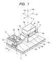
- Fig. 1 is a perspective view showing principal parts of a pressable switch device according to an embodiment of the present invention
- Fig. 2 is a longitudinal sectional view of the pressable switch device according to the embodiment of the present invention
- Fig. 3 is a cross-sectional view of the pressable switch device according to the embodiment of the present invention
- Fig. 4 is a longitudinal sectional view of the overall device illustrating a state in which an operating member provided in the embodiment of the present invention is press-operated
- Fig. 5 is a side view of a sliding part and a sliding holding part, illustrating the sliding part when the operating member provided in the embodiment of the present invention is press-operated.
- the pressable switch device of the present embodiment is constructed as shown in Figs. 1 to 3.
- the pressable switch device of the present embodiment as shown in Figs. 2 and 3, comprises a casing 1 which receives principal parts shown in Fig. 1.
- the casing 1 includes a casing body 2, a cover 3 which covers an upper portion of the casing body 2, and a base 4 which forms a bottom plate of the casing 1.
- the casing body 2 is provided with an operating member 5 which is supported so as to be displaceable in a direction orthogonal to the base 4, i.e., in a vertical direction in Fig. 2, and which is formed long in a direction orthogonal to a displacement direction 100.
- the operating member 5 has a head 5a including a top face which receives a pressing force from an operator at the time of pressing operation, a body 5b formed larger in its cross-sectional area than the head 5a, and a neck 5c formed between the head 5a and the body 5b.
- An upper portion of the casing body 2 and an upper portion of the cover 3 are respectively provided with through-holes 2a and 3a which pass vertically therethrough.
- the head 5a and the neck 5c of the operating member 5 are inserted through the through-hole 2a, and only the head 5a is inserted through the through-hole 3a to protrude from the cover 3. Further, the body 5b of the operating member 5 is formed larger than the through-hole 2a, which prevents the operating member 5 from coming out of the through-hole 2a.
- the base 4 is provided with a switch 6 which operates according to the displacement of the operating member 5 in a direction closer to the base 4.
- the switch 6 has a driving body 7 which is given an operating force for driving to slide on, for example, the base 4, a movable contact 8 which moves with the sliding of the driving body 7, and first and second fixed contacts 9 and 10 which are brought into contact with or separated from the movable contact 8.
- Biasing means i.e., a coil spring 11 biases the driving body 7 to return the driving body 7 onto the first fixed contact 9.
- the case body 2 is formed with a spring inserting part 2b into which one end of the coil spring 11 is inserted.
- the driving body 7 is also formed with a protrusion 7a onto which the other end of the coil spring 11 is fitted.
- a wall of the casing body 2 outside the spring inserting part 2b is formed with a pair of guide walls 2c and 2d, between which the driving body 7 is slidably fitted, for guiding the linear movement of the driving body 7.
- the driving body 7 is open at a bottom face thereof, and has a movable contact receiving hole 7b which receives the movable contact 8 so as to expose it to the outside of the movable body. Further, the driving body 7 has a spring receiving hole 7c continued to the movable contact receiving hole 7b for receiving a coil spring 12. Specifically, the coil spring 12 biases the movable contact 8 such that the movable contact 8 is always kept in a pressure contact with a top face of the base 4.
- the first and second fixed contacts 9 and 10 are buried in the base 4 such that they are exposed at predetermined intervals on the top face of the base 4 on a track of movable contact 8.
- the operating member 5 is mounted with a tilt prevention member, i.e., a crank member 13 which prevents the tilting of the operating member 5 caused by pressing an end of the operating member 5 in a longitudinal direction 101.
- the crank member 13 is formed by bending a metallic rod-shaped body.
- the crank member 13 has a shank 13a formed at the intermediate portion of the crank member, disposed along the longitudinal direction 101 of the operating member 5, and rotatably held by the operating member 5, rotating parts 13b and 13c which are respectively provided at opposite ends of the shank 13a and rotate about the shank 13a, and sliding parts 13d and 13e which are respectively provided in the rotating parts 13b and 13c and slidably held by the base 4.
- the shank 13a of the crank member 13 is disposed at one corner which is defined by the body 5b and the neck 5c of the operating member 5 in a lateral direction 102 of the operating member 5.
- a top face of the body 5b in the vicinity of the corner is formed with hook-shaped parts 5d which rotatably hold the shank 13a in cooperation with the top face of the body 5b and a lateral face of the neck 5c.
- the lateral face of the neck 5c above the hook-shaped part 5d is formed with projecting parts 5e which stops the shank 13a from floating up from the top face of the body 5b in cooperation with the hook-shaped part 5d.
- the base 4 is provided with sliding holding members 14 and 15 which slidably hold the sliding parts 13d and 13e.
- the sliding holding member 14 is composed of a U-shaped (in plan view) member which has a slit 14a within which one sliding part 13d slides.
- the sliding holding member 15 is also composed of a U-shape (in side view) member which has a slit within which the other sliding part 13e slides.
- the switch 6 is provided outside a projection plane 16 of the operating member 5 with respect to the base 4, for example, at the side of the operating member 5 in the longitudinal direction 101. Also, the sliding part 13d of the crank member 13 is interlocked with the driving body 7 of the switch 6.
- the shank 13a and the sliding part 13d of the crank member 13 are formed to extend in directions opposite to each other from the rotating part 13b.
- the crank member 13 is formed such that the shank 13a extends from the rotating part 13b toward the deep side (from the bottom toward the top in Fig. 3), the sliding part 13d extends from the rotating part 13b toward the front side (from the top toward the bottom in Fig. 3), and similarly, the shank 13a extends from the rotating part 13c toward the front side, and the sliding part 13e extends toward the deep side.
- the shank 13a is located away from a plane 17, which includes a centerline of the operating member 5 in the lateral direction 102 thereof, parallel to the longitudinal direction 101.
- the sliding part 13d is located closer to the plane 17 than to the shank 13a.
- the driving body 7 of the switch 6 has a flat surface 7d which abuts on the sliding part 13d of the crank member 13.
- the elastic force of the coil spring 11 is transmitted to the sliding part 13d and the shank 13a of the crank member 13 to act on the projections 5e of the neck 5c of the operating member 5, and to bias the operating member 5 upward.
- the operating member 5 is kept in a state in which an upper half of the head 5a thereof protrudes from the cover 3.
- the sliding part 13d presses the driving body 7 to cause it to slide leftwards, whereby the movable contact 8 slides leftwards from the first fixed contact 9. Then, as shown in Fig. 4, when almost the entire head 5a of the operating member 5 is pushed into the cover 3, the driving body 7 reaches the second fixed contact 10, whereby the movable contact 8 comes into contact with the second fixed contact 10.
- the elastic force of the coil spring 11 causes the driving body 7 to return to the first fixed contact 9 from the second fixed contact 10.
- the movable contact 8 also returns to the state that comes in contact with the first fixed contact 9 from the state that comes in contact with the second fixed contact 10.
- the driving body 7 pushes back the sliding part 13d of the crank member 13.
- the sliding part 13d slides rightward along the slit 14a of the sliding holding member 14, and similarly, the sliding part 13e also slides along the slit of the sliding holding member 15.
- the rotating parts 13b and 13c rotates counterclockwise (in the direction opposite to that indicated by the arrow B) about the shank 13a.
- an upward pressing force acts on the projections 5e of the neck 5c of the operating member 5 from the shank 13a. This allows the operating member 5 to be pushed up and returned to an initial position shown in Fig. 2.
- the switch 6 is placed outside the projection plane 16 of the operating member 5 with respect to the base 4, for example, at the side of the operating member 5 in the longitudinal direction 101, and the sliding part 13d of the crank member 13 is interlocked with the driving body 7 of the switch 6. Since this construction eliminates the need to arrange the operating member 5 in line with the switch 6 in the displacement direction 100 of the operating member 5, it is possible to reduce the size of a pressable switch device in the displacement direction 100 of the operating member 5 as much as the space conventionally needed for arranging the switch 6. Accordingly, it is possible to contribute to the miniaturization of the pressable switch devices.
- the shank 13a and the sliding part 13d of the crank member 13 extend in directions opposite to each other from the rotating part 13b
- the shank 13a and the sliding part 13e similarly extend in opposite directions to each other from the rotating part 13c
- the switch 6 is placed at the side of the operating member 5 in the longitudinal direction 101 of the operating member 5.
- the sliding parts 13d and 13e slide in the lateral direction of the operating member 5 at the side of the operating member 5 in the longitudinal direction 101 of the operating member 5.
- the sliding of the sliding parts 13d and 13e brings the operation of the driving body 7 of the switch 6 disposed at the side of the operating member 5 in the longitudinal direction 101 of the operating member 5, and brings the driving of the driving body 7 in the lateral direction 102 of the operating member 5.
- the operating member 5 can be designed without considering the effects of having the operating member 5 interfering with the driving body 7. As a result, the degree of freedom of a design of the operating member 5 can be enhanced.
- the shank 13a of the crank member 13 is located away from the plane 17, including a centerline of the operating member 5 in the lateral direction 102 thereof, parallel to the longitudinal direction 101, and the sliding parts 13d and 13e are located closer to the plane 17 than to the shank 13a.
- the lateral direction 102 of the operating member 5 it is possible to bring the occupying range of the operating member 5 and the driving range of the driving body 7 close to each other, or to make the occupying range and the driving range overlap each other. As a result, it is possible to reduce the size of a pressable switch device in the lateral direction 102 of the operating member 5.
- the driving body 7 of the switch 6 has the flat surface 7d which abuts on the sliding part 13d of the crank member 13.
- the sliding part 13d can be interlocked with the driving body 7 as long as the manufacturing error is within a range which allows the sliding part 13d to abut on the flat surface 7d of the driving body 7.
- the flat surface 7d of the driving body 7 can compensate the manufacturing error occurs in the positional relationship between the driving body 7 and the sliding part 13d.
- the shank 13a and the sliding part 13d of the crank member 13 extend in directions opposite to each other from the rotating part 13b, the shank 13a and the sliding part 13e similarly extend in directions opposite to each other from the rotating part 13c, and the switch 6 is placed at the side of the operating member 5 in the longitudinal direction 101 of the operating member 5.
- the present embodiment is not limited to the above construction.
- the shank 13a and the sliding part 13d of the crank member 13 may extend parallel to each other, the shank 13a and the sliding part 13e may similarly extend parallel to each other from the rotating part 13c, and the switch 6 may be placed at the side of the operating member 5 in the lateral direction 102 of the operating member 5.
- This construction makes it possible to easily miniaturize a pressable switch device in the displacement direction 100 of the operating member 5, and to contribute to the miniaturization of the pressable switch devices.
Landscapes
- Push-Button Switches (AREA)
Applications Claiming Priority (2)
| Application Number | Priority Date | Filing Date | Title |
|---|---|---|---|
| JP2003391231 | 2003-11-20 | ||
| JP2003391231A JP4249600B2 (ja) | 2003-11-20 | 2003-11-20 | 押圧操作型スイッチ装置 |
Publications (1)
| Publication Number | Publication Date |
|---|---|
| EP1533819A1 true EP1533819A1 (de) | 2005-05-25 |
Family
ID=34431609
Family Applications (1)
| Application Number | Title | Priority Date | Filing Date |
|---|---|---|---|
| EP04027440A Withdrawn EP1533819A1 (de) | 2003-11-20 | 2004-11-18 | Tastschalter Vorrichtung |
Country Status (2)
| Country | Link |
|---|---|
| EP (1) | EP1533819A1 (de) |
| JP (1) | JP4249600B2 (de) |
Families Citing this family (1)
| Publication number | Priority date | Publication date | Assignee | Title |
|---|---|---|---|---|
| JP2022116382A (ja) * | 2019-06-26 | 2022-08-10 | アルプスアルパイン株式会社 | プッシュスイッチ |
Citations (4)
| Publication number | Priority date | Publication date | Assignee | Title |
|---|---|---|---|---|
| US3857007A (en) * | 1972-03-08 | 1974-12-24 | Leuenberger P | Electric switch |
| JPS63308824A (ja) * | 1987-06-10 | 1988-12-16 | Oki Electric Ind Co Ltd | 大形キ− |
| EP0966009A2 (de) * | 1998-06-18 | 1999-12-22 | Matsushita Electric Industrial Co., Ltd. | Tastschalter und Eingabegerät damit |
| US20020064410A1 (en) * | 2000-11-28 | 2002-05-30 | Silitek Corporation | Keycap assembly |
-
2003
- 2003-11-20 JP JP2003391231A patent/JP4249600B2/ja not_active Expired - Fee Related
-
2004
- 2004-11-18 EP EP04027440A patent/EP1533819A1/de not_active Withdrawn
Patent Citations (4)
| Publication number | Priority date | Publication date | Assignee | Title |
|---|---|---|---|---|
| US3857007A (en) * | 1972-03-08 | 1974-12-24 | Leuenberger P | Electric switch |
| JPS63308824A (ja) * | 1987-06-10 | 1988-12-16 | Oki Electric Ind Co Ltd | 大形キ− |
| EP0966009A2 (de) * | 1998-06-18 | 1999-12-22 | Matsushita Electric Industrial Co., Ltd. | Tastschalter und Eingabegerät damit |
| US20020064410A1 (en) * | 2000-11-28 | 2002-05-30 | Silitek Corporation | Keycap assembly |
Also Published As
| Publication number | Publication date |
|---|---|
| JP2005158306A (ja) | 2005-06-16 |
| JP4249600B2 (ja) | 2009-04-02 |
Similar Documents
| Publication | Publication Date | Title |
|---|---|---|
| US7670160B2 (en) | Card connector | |
| US6966786B1 (en) | Card socket | |
| JP2008157456A (ja) | 係合装置 | |
| JP2022141410A (ja) | 電磁継電器 | |
| EP1113473A2 (de) | Hebelschalter und Detektoranordnung mit diesem Schalter | |
| CN101752130B (zh) | 带固定接点壳体及具备该壳体的滑动开关 | |
| JP3923732B2 (ja) | スイッチ装置 | |
| US6433291B1 (en) | Switch device | |
| US20060219532A1 (en) | Electrical switch | |
| EP1533819A1 (de) | Tastschalter Vorrichtung | |
| JPH0577835U (ja) | スイッチ装置 | |
| JP2009087679A (ja) | カード用コネクタ | |
| JP2003331690A (ja) | スイッチ装置 | |
| JP2023131031A (ja) | 電磁継電器 | |
| JP2005332688A (ja) | スイッチ装置 | |
| JP2006164891A (ja) | スイッチ装置 | |
| JP3767996B2 (ja) | プッシュスイッチ装置 | |
| JP2003346602A (ja) | スライド型電気部品 | |
| JP2007157644A (ja) | スイッチ装置 | |
| US6060670A (en) | Slide switch | |
| JP4653001B2 (ja) | スイッチ装置 | |
| JP4316608B2 (ja) | スライド機構 | |
| JP2007207563A (ja) | 電気装置の操作機構 | |
| JP3286302B2 (ja) | キースイッチ装置 | |
| KR200431025Y1 (ko) | 시소 스위치 장치 |
Legal Events
| Date | Code | Title | Description |
|---|---|---|---|
| PUAI | Public reference made under article 153(3) epc to a published international application that has entered the european phase |
Free format text: ORIGINAL CODE: 0009012 |
|
| AK | Designated contracting states |
Kind code of ref document: A1 Designated state(s): AT BE BG CH CY CZ DE DK EE ES FI FR GB GR HU IE IS IT LI LU MC NL PL PT RO SE SI SK TR |
|
| AX | Request for extension of the european patent |
Extension state: AL HR LT LV MK YU |
|
| 17P | Request for examination filed |
Effective date: 20050614 |
|
| AKX | Designation fees paid |
Designated state(s): DE GB |
|
| GRAP | Despatch of communication of intention to grant a patent |
Free format text: ORIGINAL CODE: EPIDOSNIGR1 |
|
| RIN1 | Information on inventor provided before grant (corrected) |
Inventor name: SHIRASAKA, TAKESHI |
|
| STAA | Information on the status of an ep patent application or granted ep patent |
Free format text: STATUS: THE APPLICATION IS DEEMED TO BE WITHDRAWN |
|
| 18D | Application deemed to be withdrawn |
Effective date: 20110929 |