EP1534143B1 - Canules et ensembles porte-canule - Google Patents
Canules et ensembles porte-canule Download PDFInfo
- Publication number
- EP1534143B1 EP1534143B1 EP03793357A EP03793357A EP1534143B1 EP 1534143 B1 EP1534143 B1 EP 1534143B1 EP 03793357 A EP03793357 A EP 03793357A EP 03793357 A EP03793357 A EP 03793357A EP 1534143 B1 EP1534143 B1 EP 1534143B1
- Authority
- EP
- European Patent Office
- Prior art keywords
- cannula
- portions
- assembly
- fitting
- cannula device
- Prior art date
- Legal status (The legal status is an assumption and is not a legal conclusion. Google has not performed a legal analysis and makes no representation as to the accuracy of the status listed.)
- Expired - Lifetime
Links
- 210000000056 organ Anatomy 0.000 title claims abstract description 75
- 238000007789 sealing Methods 0.000 claims abstract description 76
- 230000006835 compression Effects 0.000 claims abstract description 36
- 238000007906 compression Methods 0.000 claims abstract description 36
- 239000012530 fluid Substances 0.000 claims description 35
- 230000000295 complement effect Effects 0.000 claims description 14
- 239000000463 material Substances 0.000 claims description 9
- 238000004891 communication Methods 0.000 claims description 6
- 210000003484 anatomy Anatomy 0.000 claims description 2
- 239000013536 elastomeric material Substances 0.000 claims 2
- 239000012780 transparent material Substances 0.000 claims 1
- 230000010412 perfusion Effects 0.000 abstract description 29
- 210000001367 artery Anatomy 0.000 abstract description 18
- 229920001971 elastomer Polymers 0.000 abstract description 12
- 239000000806 elastomer Substances 0.000 abstract description 12
- 230000032258 transport Effects 0.000 abstract description 8
- 230000035899 viability Effects 0.000 abstract description 4
- 230000000007 visual effect Effects 0.000 abstract description 2
- 238000013022 venting Methods 0.000 abstract 1
- 210000003734 kidney Anatomy 0.000 description 15
- 241001631457 Cannula Species 0.000 description 13
- 238000000034 method Methods 0.000 description 11
- 210000000709 aorta Anatomy 0.000 description 10
- 210000002254 renal artery Anatomy 0.000 description 7
- 229920001296 polysiloxane Polymers 0.000 description 4
- 239000004800 polyvinyl chloride Substances 0.000 description 4
- 238000011084 recovery Methods 0.000 description 4
- 229920003031 santoprene Polymers 0.000 description 4
- 210000002445 nipple Anatomy 0.000 description 3
- 238000003825 pressing Methods 0.000 description 3
- 238000003860 storage Methods 0.000 description 3
- 208000004434 Calcinosis Diseases 0.000 description 2
- 102000001554 Hemoglobins Human genes 0.000 description 2
- 108010054147 Hemoglobins Proteins 0.000 description 2
- 230000000712 assembly Effects 0.000 description 2
- 238000000429 assembly Methods 0.000 description 2
- QVGXLLKOCUKJST-UHFFFAOYSA-N atomic oxygen Chemical compound [O] QVGXLLKOCUKJST-UHFFFAOYSA-N 0.000 description 2
- 210000004369 blood Anatomy 0.000 description 2
- 239000008280 blood Substances 0.000 description 2
- 238000004113 cell culture Methods 0.000 description 2
- -1 for example Polymers 0.000 description 2
- 230000002631 hypothermal effect Effects 0.000 description 2
- 208000028867 ischemia Diseases 0.000 description 2
- 210000004185 liver Anatomy 0.000 description 2
- 230000007246 mechanism Effects 0.000 description 2
- 230000004048 modification Effects 0.000 description 2
- 238000012986 modification Methods 0.000 description 2
- 238000012544 monitoring process Methods 0.000 description 2
- 229910052760 oxygen Inorganic materials 0.000 description 2
- 239000001301 oxygen Substances 0.000 description 2
- 230000037452 priming Effects 0.000 description 2
- 239000012858 resilient material Substances 0.000 description 2
- 239000007779 soft material Substances 0.000 description 2
- 230000007480 spreading Effects 0.000 description 2
- 238000003892 spreading Methods 0.000 description 2
- 241000510097 Megalonaias nervosa Species 0.000 description 1
- 238000004458 analytical method Methods 0.000 description 1
- 239000003963 antioxidant agent Substances 0.000 description 1
- 239000002473 artificial blood Substances 0.000 description 1
- 230000003190 augmentative effect Effects 0.000 description 1
- 238000010009 beating Methods 0.000 description 1
- 239000010836 blood and blood product Substances 0.000 description 1
- 230000017531 blood circulation Effects 0.000 description 1
- 229940125691 blood product Drugs 0.000 description 1
- 230000036770 blood supply Effects 0.000 description 1
- 239000003795 chemical substances by application Substances 0.000 description 1
- 238000010367 cloning Methods 0.000 description 1
- 239000000839 emulsion Substances 0.000 description 1
- 210000003743 erythrocyte Anatomy 0.000 description 1
- NBVXSUQYWXRMNV-UHFFFAOYSA-N fluoromethane Chemical compound FC NBVXSUQYWXRMNV-UHFFFAOYSA-N 0.000 description 1
- 238000003306 harvesting Methods 0.000 description 1
- 230000002440 hepatic effect Effects 0.000 description 1
- 230000006872 improvement Effects 0.000 description 1
- 239000007788 liquid Substances 0.000 description 1
- 230000014759 maintenance of location Effects 0.000 description 1
- 239000002184 metal Substances 0.000 description 1
- 229910052751 metal Inorganic materials 0.000 description 1
- 230000001453 nonthrombogenic effect Effects 0.000 description 1
- 238000006213 oxygenation reaction Methods 0.000 description 1
- 238000005502 peroxidation Methods 0.000 description 1
- 210000002826 placenta Anatomy 0.000 description 1
- 239000004033 plastic Substances 0.000 description 1
- 229920003023 plastic Polymers 0.000 description 1
- 238000004321 preservation Methods 0.000 description 1
- 238000005086 pumping Methods 0.000 description 1
- 150000003254 radicals Chemical class 0.000 description 1
- 238000011160 research Methods 0.000 description 1
- 230000001225 therapeutic effect Effects 0.000 description 1
- 238000012546 transfer Methods 0.000 description 1
- 230000007704 transition Effects 0.000 description 1
- 238000002054 transplantation Methods 0.000 description 1
- 230000002792 vascular Effects 0.000 description 1
- 210000005166 vasculature Anatomy 0.000 description 1
Images


Classifications
-
- A—HUMAN NECESSITIES
- A61—MEDICAL OR VETERINARY SCIENCE; HYGIENE
- A61B—DIAGNOSIS; SURGERY; IDENTIFICATION
- A61B17/00—Surgical instruments, devices or methods
-
- A—HUMAN NECESSITIES
- A61—MEDICAL OR VETERINARY SCIENCE; HYGIENE
- A61B—DIAGNOSIS; SURGERY; IDENTIFICATION
- A61B17/00—Surgical instruments, devices or methods
- A61B17/11—Surgical instruments, devices or methods for performing anastomosis; Buttons for anastomosis
-
- A—HUMAN NECESSITIES
- A61—MEDICAL OR VETERINARY SCIENCE; HYGIENE
- A61B—DIAGNOSIS; SURGERY; IDENTIFICATION
- A61B17/00—Surgical instruments, devices or methods
- A61B2017/00831—Material properties
- A61B2017/00902—Material properties transparent or translucent
- A61B2017/00907—Material properties transparent or translucent for light
-
- A—HUMAN NECESSITIES
- A61—MEDICAL OR VETERINARY SCIENCE; HYGIENE
- A61B—DIAGNOSIS; SURGERY; IDENTIFICATION
- A61B17/00—Surgical instruments, devices or methods
- A61B2017/00969—Surgical instruments, devices or methods used for transplantation
Definitions
- the invention relates to cannulas and clamping methods. More specifically, the invention relates to cannulas, cannula mount assemblies and clamping methods for perfusing one or more organs to monitor, treat, sustain and/or restore the viability of the organ(s) and/or for transporting and/or storing the organ(s).
- cannula in general use has other meanings, the term cannula is used generically throughout the specification to refer to a clamp or other device that provides a connection through which a fluid flow may be established.
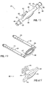
- a first type of cannula as described in U.S. Patent No. 5,728,115 to Westcott et al. is shown in Figs. 1-3.
- a clamping device (cannula) 10 is used to couple the perfusion cannula to the renal aorta 34.
- the clamp 10 includes two longitudinal members 12 and 14 which pivot about a pin 16.
- the proximal end of the member 12 includes an integral handle 18, while the proximal end of the member 14 includes an integral handle 20.
- the distal end of the member 12 includes an integral clamp head 24, while the distal end of the member 14 includes an integral clamp head 26.
- Clamp head 26 includes a nipple 28 attached thereto. Movement of the handles 18 and 20 toward one another forces the members 12 and 14 to pivot about the pin 16, thereby forcing the clamp heads 24 and 26 of the members 12 and 14 away from one another.
- a spring 22 is positioned between the handles 18 and 20 in order to bias the handles apart. This, in turn, tends to force the clamp heads 24 and 26 together. Therefore, the clamp heads 24 and 26 of the distal ends of the members 12 and 14 are engaged in clamping relationship unless an external compressive force is applied to the handles 18 and 20.
- the distal end of the member 12 comprises an elongated, hollow, annular clamp head 24.
- a lumen 32 extends through the nipple 28.
- the clamp 10 is attached to the renal aorta 34 of a donor organ such as a kidney 36 by opening the clamp 10, passing the distal end 38 of the renal aorta 34 through the annular clamp head 24, holding the distal end 38 of the renal aorta 34 over the annular clamp head 24, and releasing pressure on the handles of the clamp 10 in order to allow the clamp head 26 to engage the distal end 38 of the renal aorta 34 against the annular clamp head 24.
- a catheter 40 may then be attached to the nipple 28 in order to provide perfusion of liquid through the lumen 32 and into the renal aorta 34.
- FIG. 4 A second type of cannula 50, used when no aortic patch is available, is shown in Fig. 4. No aortic patch may be available due to anatomical constraints or a living donor recovery.
- An infuse line (not shown) is connected to a top tube portion 52 of the cannula 50.
- a lower tube portion 54 of the cannula is inserted into the renal artery. The lower tube portion 54 may be sutured into place.
- the present invention focuses on avoiding damage to an organ during perfusion while connecting the organ to a machine or system for monitoring, treating, sustaining and/or restoring the viability of the organ and preserving the organ for storage and/or transport.
- the invention is directed to apparatus for connecting an organ to be perfused with a perfusion machine or system that monitors, treats, sustains and/or restores the viability of the organ and/or that transports and/or stores the organ.
- the apparatus according to the invention are suitable for use with the perfusion systems and methods described in U.S. Patent No. 6,209,343.
- apparatus according to the invention are suitable for use with organ perfusion at normothermic temperatures and organ perfusion at hypothermic temperatures.
- Apparatus according to the invention are suitable for use with an organ cassette, such as that disclosed in the '525 application, and/or with a mother unit, and/or with a portable transport apparatus, such as, for example, a cooler or a portable container such as that disclosed in co-pending WO00/18255.
- a portable transport apparatus such as, for example, a cooler or a portable container such as that disclosed in co-pending WO00/18255.
- Various exemplary embodiments of apparatus according to the invention are atraumatic to the aortic patch or general tissue that is to be connected.
- soft medical grade elastomers are utilized to contact the delicate inner wall of the patch or tissue.
- the sealing force is spread out over a large surface area, helping to reduce the force on a specific section of the patch or tissue.
- Various exemplary embodiments of apparatus according to the invention seal against aortic patches or other tissue with a hard plaque build-up.
- an elastomeric sealing ring is used that follows the contour of plaque build-up.
- a relatively large sealing surface provides good contact.
- Various exemplary embodiments of apparatus according to the invention provide visual access to an air bubble trap.
- at least a portion of the cannula is made of a translucent material to provide viewing into an upper portion of the cannula that traps air bubbles.
- Various exemplary embodiments of apparatus according to the invention provide a means to prime and/or vent air bubbles from the cannula, connecting tubes and/or the organ without disconnecting the cannula from the tissue.
- a fitting allows the user to open a port to let air out.
- a relatively large sealing ring accommodates patches or tissues containing multiple arteries.
- a fluid exit may be shaped to accommodate patches or tissues containing multiple arteries.
- a fitting allows the user to network multiple cannulas that are each connected to patches or placed straight into an artery.
- aortic patch or tissue may be positioned and fixed to the cannula prior to clamping.
- the aortic patch or tissue may be located and fixed onto flanges prior to clamping, for example, with standard surgical clamps.
- the cannula includes locating or positioning features that may be securely positioned, for example, onto an organ platform or chair, such as the chair described in the incorporated '525 application, to keep the artery from getting twisted and/or stressed.
- Various exemplary embodiments of apparatus according to the invention provide parallel sealing surfaces.
- the sealing surfaces are not constrained by a hinge, allowing the surfaces to remain parallel during clamping.
- Various exemplary embodiments of apparatus according to the invention provide a secure connection to an infuse line.
- a locking fitting ensures a secure, leak-proof connection to tubing of a perfusion machine or system.
- a cannula that is suitable for multiple size organs, i.e., one-size-fits-all.
- a bottom portion of the cannula may be shaped, for example with standard scissors or knives, to accommodate various patch sizes and multiple arteries.
- an inner clamp surface can be shaped cylindrically to allow the aortic patch or tissue to be fixed in its natural shape.
- organs would be procured in a manner which limits their warm ischemia time to essentially zero.
- many organs especially from non-beating heart donors, are procured after extended warm ischemia time periods (i.e. 45 minutes or more).
- the machine perfusion of these organs at low temperature has demonstrated significant improvement (Transpl Int 1996 Daemen).
- Numerous control circuits and pumping configurations have been utilized to achieve this objective and to machine perfuse organs in general. See, for example, U.S. Patents Nos. 5,338,662 and 5,494,822 to Sadri; U.S. Patent No. 4,745,759 to Bauer et al.; U.S. Patents Nos.
- the cannulas according to the invention may be used in conjunction with apparatus and methods described in U.S. Patents Nos. 6,014,864, 6,183,019, 6,241,945 and 6,485,450 to Owen. While these apparatus and methods are related to organ recovery and transplantation, the cannulas and clamping methods according to the invention may also be used in various other medical procedures and with various other medical equipment where clamping with fluid flow is desired. Thus, the cannulas according to the invention are not limited to the applications described below in conjunction with the exemplary embodiments.
- Fig. 5 shows a perfusion clamping apparatus or cannula 100 according to a first exemplary embodiment of the invention.
- the cannula 100 is capable of connecting one or more arteries of an organ to a perfusion machine or system (not shown), for example, by connection to tubing of the perfusion machine or system.
- All medical fluid contact surfaces are preferably formed of or coated with materials compatible with the medical fluid used, preferably non-thrombogenic materials.
- the medical fluid for perfusion may be any suitable medical fluid.
- it may be a simple crystalloid solution, or may be augmented with an appropriate oxygen carrier.
- the oxygen carrier may, for example, be washed, stabilized red blood cells, cross-linked hemoglobin, pegolated hemoglobin or fluorocarbon based emulsions.
- the medical fluid may also contain antioxidants known to reduce peroxidation or free radical damage in the physiological environment and specific agents known to aid in tissue protection. Further, the medical fluid may also include blood or blood products.
- the cannula 100 is shown in Fig. 5 in a closed or clamping condition and in Fig. 6 in an exploded condition.
- the cannula 100 comprises a top portion 101, a bottom portion 102, a sealing ring 103 and compression straps 104.
- the cannula 100 may include a cannula mount in the form of a locating or positioning structure 117 that can be used to connect the cannula 100 to an organ platform or chair (not shown). While the relative terms “top” and “bottom” are used to refer to the various embodiments as shown in the Figs. throughout this application, it should be understood that the various parts may be otherwise oriented, and that the relative terms “top” and “bottom” are not limiting.
- the top and bottom portions 101 and 102 seal to an aortic patch or other tissue by clamping the aortic patch or other tissue therebetween.
- the compression straps 104 are used to force the top portion 101 and the bottom portion 102 together and may be made of a resilient material, such as an elastomer.
- the sealing ring 103 may or may not be captured between the aortic patch or other tissue and the top portion 101 or the bottom portion 102, or two sealing rings 103 may be present and captured between each of the top and bottom portions 101, 102 and the aortic patch or other tissue.
- the sealing ring 103 may be included or not, and may be incorporated into either or both sealing surfaces of the top and bottom surfaces 101 and 102, described below.
- the top portion 101 has a fitting 105 that is used to connect to a perfusion machine or other fluid source, for example, by tubing (not shown).
- the top portion 101, or a portion thereof, may be constructed of a clear or translucent material that allows a user to visually check for air bubbles. Any air that is present in the cannula will collect at an upper portion 106 of the top portion 101.
- a "lateral" fluid flow i.e., a flow of fluid that is substantially perpendicular to the direction of fluid flow to and from the tissue to which the cannula is attached.
- the one or more fittings of the cannula are oriented to have an axis of fluid flow that is substantially perpendicular to an axis of fluid flow into/out of the hole or lumen of the cannula.
- This "lateral" fluid flow arrangement allows the cannula to be connected to tubing of an organ transporter, for example, that is substantially in a single plane. Further, multiple cannulas may be connected and even interconnected within substantially the same plane.
- a second fitting 107 may be provided on the top portion 101 for priming and/or air bubble removal.
- the second fitting 107 comprises a port or valve for such purpose.
- the second fitting 107 may also be used to network multiple cannulas, for example, by connecting tubing in parallel, for example, by running a split infuse line to the first fitting of each cannula, or in series, for example, by connecting the first fitting of a cannula to the second fitting of another cannula.
- Standard luer geometry or other suitable structure may be used for fittings 105 and 107.
- the top portion 101 has a top sealing surface 108.
- the top sealing surface 108 may be made of a soft elastomer, such as, for example, SANTOPRENE ® made by advanced Elastomer Systems. Any other suitable materials may be used as well, such as silicone or flexible polyvinylchloride (PVC) and the like.
- the top sealing surface 108 is shown in this embodiment as elliptical, although other suitable shapes, such as oval, circular and rectangular are also contemplated.
- the top sealing surface 108 may include ribs, ridges, cuts and/or protrusions that create a tortuous fluid path. The tortuous path serves to increase surface area by providing bends, turns and/or edges that increase the robustness of the seal and/or the likelihood of a sufficient seal.
- the top portion 101 may include engagement members 109 that accept a free end of the compressions straps 104 and fixing members 110 that hold a portion of the compression straps 104 with the cannula 100 in a clamping condition. While the engagement members 109 are shown as slots in this embodiment, any suitable structure or technique, either known or hereafter developed, that provides attachment or retention of a free end of the straps 104 may be used.
- the top portion 101 may also have a pre-positioning structure 111, as discussed further below.
- engagement members 109 and fixing members 110 are shown as part of the top portion 101, these members may be part of the bottom portion 102. In other words, such features of the cannula 100 may be reversed.
- the bottom portion 102 has a bottom sealing surface 112 that mates with the top sealing surface 108.
- the bottom sealing surface 112 may be made of a soft elastomer, as with the top sealing surface 108.
- the bottom sealing surface 112 may also have ribs, ridges, cuts and/or protrusions that create a tortuous fluid path.
- the bottom portion 102 may include flanges or other protrusions 113 near the bottom sealing surface 112.
- the flanges 113 may be used to position the aortic patch or other tissue prior to assembly, for example, by clamping the aortic patch or other tissue to the flanges 113 with common surgical tools.
- a hole 114 may be located in the bottom portion 102.
- the aortic patch or other tissue is positioned by feeding the patch through the hole 114 and laying and/or spreading the patch across the bottom sealing surface 112.
- the hole 114 may be designed to accept varying patch or other tissue sizes and/or patches or other tissues with multiple arteries.
- the bottom portion 102 may include posts 115 that protrude outwardly.
- the compression straps 104 can be wrapped around the posts 115.
- Other suitable structures either known or hereafter developed, that are capable of pressing and holding the top and bottom portions 101 and 102 together may be used in place of the compression straps 104.
- rigid clips or compliant springs may be used in place of the compression straps 104.
- Such clips or springs may be made of any suitable material, such as metal or plastic.
- the bottom portion 102 may include complementary pre-positioning structure 116 that complements the pre-positioning structure 111 of the top portion 101.
- the pre-positioning structure 111 is shown as a bar and the complementary pre-positioning structure 116 is shown as a pair of hooks or flanges. The hooks or flanges preferably engage the bar to allow the sealing surfaces 108 and 112 of the top and bottom portions 101 and 102 to remain parallel prior to closure and clamping.
- the structures 111 and 116 may be any suitable structures, either known or hereafter developed, that cooperate to provide pre-positioning of the top and bottom portions 101 and 102.
- the locating or positioning structure 117 may be connected to the bottom portion 102, although it may alternatively or additionally be connected to the top portion 101.
- the positioning structure 117 is designed to position the cannula 100 relative to the organ and/or the organ platform or chair.
- the positioning structure 117 may also be designed to position the artery relative to the cannula 100 and/or the organ.
- the positioning structure 117 helps to hold the artery at a fixed tension and helps to keep the artery from getting twisted or stressed by securely positioning the cannula 100 onto the organ platform or chair.
- the configuration and/or features of the positioning structure 117 will vary depending on the configuration of the organ platform or chair.
- a post near a middle of the positioning structure 117 may provide a snap-fit with a corresponding structure of the organ platform or chair.
- horizontal ribs or a washboard structure may engage or mate with a corresponding structure of the organ platform or chair.
- Other fastening arrangements including, but not limited to, clips, clamps, snaps, hook and loop fasteners (e.g., VELCRO® fasteners) and multi-part systems are contemplated as well.
- the sealing ring 113 may be shaped corresponding to the shape of the top and/or bottom portions 101 and 102, particularly the top and bottom sealing surfaces 108 and 112.
- the sealing ring 103 may be constructed of a soft material, such as SANTOPRENE ® made by advanced Elastomer Systems, silicone or flexible polyvinylchloride (PVC) and the like, which allows the sealing ring 103 to surround and follow the contour of plaque or calcium deposits on the aortic patch or other tissue.
- the sealing ring 103 may also have details that help to locate the top portion 101 relative to the bottom portion 102 prior to closure.
- undercuts in the sealing ring 103 may be arranged to mate with corresponding ribs formed on the top and/or bottom portions 101 and 102.
- the sealing ring 103 may be made integral with the top and/or bottom portions 101 and 102.
- An exemplary compression strap 104 is shown in detail in Fig. 10.
- a free end of the compression strap 104 preferably has a shaped end or flange 118 that is configured to be engaged by engagement members 109 of the top portion 101.
- the tension of the compression strap 104 may be varied, for example, by engaging one of a plurality of holes 119 to fixing members 110 of the top portion 101.
- a textured surface, such as ridges, may be located at an end of the compression strap 104 (opposite the flange 118) to increase a user's grip for tensioning the compression strap 104.
- the top and bottom portions 101 and 102 of the cannula 100 are pulled together to create a seal.
- Fig. 11. shows a perfusion clamping apparatus or cannula 400 according to a fourth exemplary embodiment of the invention assembled with a cannula mount 500 and a platform 600.
- the cannula 400 is capable of connecting one or more arteries of an organ to a perfusion machine or system (not shown), for example, by connection to tubing of the perfusion machine or system.
- the cannula 400 is shown in Fig. 11 in a closed or clamping condition and in Fig. 19 in an exploded condition.
- the cannula 400 comprises a top portion 401, a bottom portion 402, a sealing ring 403 and compression straps 404.
- the cannula 400 is supported relative to the platform 600 via the cannula mount 500.
- the top and bottom portions 401 and 402 seal to an aortic patch or other tissue by clamping the aortic patch or other tissue therebetween.
- the compression straps 404 may be used to force the top portion 401 and the bottom portion 402 together and may be made of a resilient material, such as an elastomer.
- the sealing ring 403 may be captured between the aortic patch or other tissue and the top portion 401 and/or the bottom portion 402. In the fourth embodiment, the sealing ring 403 is integral with the compression straps 404.
- the top portion 401 has a first fitting 405 that is used to connect to a perfusion machine or other fluid source, for example, by tubing (not shown).
- the first fitting 405 is in fluid communication with the chamber formed when the top and bottom portions 401 and 402 are brought together.
- the top portion 401, or a portion thereof, may be constructed of a transparent or translucent material that allows a user to visually check for air bubbles. If the cannula 400 is oriented as shown, any air that is present in the cannula will collect at an upper portion 406 of the top portion 401.
- a second fitting 407 may be provided on the top portion 401 for priming and/or air bubble removal.
- the second fitting 407 may comprise a port or valve for such purpose.
- the second fitting 407 is in fluid communication with at least one of the first fitting 405 and the chamber formed when the top and bottom portions 401 and 402 are brought together.
- the second fitting 407 may also be used to network multiple cannulas, for example, by connecting tubing in parallel, for example, by running a split infuse line to the first fitting of each cannula, or in series, for example, by connecting the first fitting of a cannula to the second fitting of another cannula.
- Standard luer geometry or other suitable structure may be used for fittings 405 and 407.
- the top portion 401 has a top sealing surface 408.
- the top sealing surface 408 may be made of a soft elastomer, such as, for example, SANTOPRENE ® made by advanced Elastomer Systems. Any other suitable materials may be used as well, such as silicone or flexible polyvinylchloride (PVC) and the like.
- the top sealing surface 408 is shown in this embodiment as elliptical, although other suitable shapes, such as oval, circular and rectangular are also contemplated.
- the top portion 401 may include fixing members 410 that hold a portion of the compression straps 404 with the cannula 400 in a clamping condition.
- the fixing members 410 are shown as posts in Fig. 13; however, any suitable structure that is capable of retaining the compression straps 404 may be used.
- fixing members 410 are shown as part of the top portion 401, these members may be part of the bottom portion 402. In other words, such features of the cannula 400 may be reversed.
- the bottom portion 402 has a bottom sealing surface 412 that corresponds with the top sealing surface 408.
- the bottom sealing surface 412 may be made of a soft elastomer, as with the top sealing surface 408.
- the bottom sealing surface 412 may include a flange 413 that extends outwardly. The flange 413 may be used to position the aortic patch or other tissue prior to assembly, for example, by clamping the aortic patch or other tissue to the flange 413 with common surgical tools.
- a hole 414 may be located in the bottom portion 402.
- the aortic patch or other tissue is positioned by feeding the patch through the hole 414 and laying and/or spreading the patch across the bottom sealing surface 412.
- the hole 414 may be designed to accept varying patch or other tissue sizes and/or patches or other tissues with multiple arteries.
- the bottom portion 402 may include posts 415 that protrude outwardly.
- the compression straps 404 can be wrapped around the posts 415.
- other suitable structures either known or hereafter developed, that are capable of pressing and holding the top and bottom portions 401 and 402 together may be used in place of the compression straps 404.
- the bottom portion 402 may include a complementary pre-positioning structure 416 that complements a pre-positioning structure 411 of the top portion 401.
- the pre-positioning structure 411 is shown as a bar and the complementary pre-positioning structure 416 is shown as a pair of hooks.
- the hooks preferably engage the bar to allow the sealing surfaces 408 and 412 of the top and bottom portions 401 and 402 to remain parallel prior to closure and clamping, for example, by providing both pivoting and linear movement of the top and bottom portions 401 and 402 relative to one another.
- the structures 411 and 416 may be any suitable structures, either known or hereafter developed, that cooperate to provide pre-positioning of the top and bottom portions 401 and 402.
- the sealing ring 403 may be shaped corresponding to the shape of the top and/or bottom portions 401 and 402, particularly the top and bottom sealing surfaces 408 and 412.
- the sealing ring 403 may be constructed of a soft material, such as SANTOPRENE ® made by advanced Elastomer Systems, silicone or flexible polyvinylchloride (PVC) and the like, which allows the sealing ring 403 to surround and follow the contour of plaque or calcium deposits on the aortic patch or other tissue.
- the sealing ring 403 may have a shape that is complementary to the shape of at least one of the top sealing surface 408 and the bottom sealing surface 412. For example, as shown in Fig. 22, the sealing ring 403 may have a recess 417 that is shaped to snugly receive the top sealing surface 408.
- Exemplary compression straps 404 are shown in detail in Fig. 15 as integral with the sealing ring 403. This arrangement eliminates a need to separately position the straps 404 relative to other parts of the cannula 400 as well as a need to secure a free end of each compression strap 104 to the top or bottom portions of the cannula 400.
- the tension of the compression straps 404 may be varied, for example, by engaging one of a plurality of holes 419 to fixing members 410 of the top portion 401.
- a textured surface, such as ridges, may be located at an end of each compression strap 404 to increase a user's grip for tensioning the compression straps 404.
- the top and bottom portions 401 and 402 of the cannula 400 are pulled together to create a seal.
- the cannula mount 500 is designed to position the cannula 400 relative to the organ (not shown) by supporting the cannula relative to the platform 600.
- the cannula mount 500 helps to hold the artery of an organ at a fixed tension and helps to keep the artery from being twisted or stressed by securely positioning the cannula 400 in relation to the platform 600.
- cannula mount 500 Details of the cannula mount 500 according to the fourth exemplary embodiment are shown in Fig. 16. It should be understood that certain features described as located on the cannula mount 500 or the cannula 400 may be reversed and located on the other. Further, certain features described as located on the cannula mount 500 or the platform 600 may be reversed and located on the other. Thus, the particular arrangement is illustrative and not limiting.
- the cannula mount 500 has a pair of substantially "U” or “C” shaped portions 502 that are adapted to removably engage a connection arm, such as the first and second fittings 405 and 407, on the cannula 400.
- the cannula mount 500 has an attachment feature 504 adapted to engage a separate support structure, such as the platform 600.
- the separate support structure may be part of the platform 600 such that the cannula mount 500 is connected directly to the platform 600. Alternatively, the separate support structure may be independently connected to the platform 600 such that the cannula mount 500 is connected indirectly to the platform 600.
- a feature of various exemplary embodiments of the cannula mount assembly according to this invention is that the cannula 400 may be positioned or located relative to the platform 600.
- the cannula mount 500 may be movably positionable on the separate support structure.
- the separate support structure may be movably positionable on the platform 600.
- the height and/or position of the cannula 400 relative to the platform 600 may be adjusted to achieve a desired positional relationship between the cannula 400 and the platform 600 and/or an organ situated on the platform 600.
- cannula 400 and the cannula mount 500 are shown as separate elements, the cannula mount 500 may be integral with part of the cannula 400.
- the attachment feature 504 may be an open slot as shown in Fig. 16 that is designed to receive a mounting portion 602 that extends from a base 604 of the platform 600.
- One side of the open slot 504 may be a resilient wall 506 that flexes to accommodate the mounting portion 602.
- the resilient wall 506 will press against the mounting portion 602 to hold the cannula mount 500 at a desired height above the base 604.
- the cannula mount 500 may include a "release mechanism.”
- the resilient wall 506 may include a pair of substantially parallel extensions as shown in Fig. 16.
- the resilient wall 506 will flex outward slightly when pressure is applied to a portion of the extensions, for example by applying a squeezing force to the extensions.
- the slight flexing of the resilient wall 506 may facilitate placement of the cannula mount 500 on the mounting portion 602 and may also facilitate movement of the cannula mount 500 on the mounting portion 602 to obtain a desired position of the cannula 400 relative to the platform 600. It should be understood that any other arrangement that allows a user to temporarily flex the resilient wall 506 may be used as well.
- the fittings 405 and 407 may include flange portions 418 and 420, respectively, that help a user to position the cannula 400 to locate the fittings 405 and 407 of the cannula 400 in the substantially "U” or “C” shaped portions 502, as shown in Fig. 11.
- the flange portions 418 and 420 each may have one or more protrusions 422 on an inner surface 424.
- the substantially “U” or “C” shaped portions 502 may have one or more complementary recesses 508 that are adapted to engage the protrusions 422 when the substantially "U” or “C” shaped portions 502 engage the fittings 405 and 407.
- the configuration and/or features of the cannula mount 500 will vary depending on the configuration of the platform 600.
- the open slot arrangement is illustrative, and any suitable connection between the cannula mount 500 and the platform 600 may be used.
- the above described apparatus and methods may be used for small or child organs as well as for large or adult organs with modification as needed. Further, while the apparatus and methods are described above with respect to transplanting organs, the apparatus and methods can also be used to provide an artificial blood supply to other tissues and cell cultures, for example, artificial placenta cell cultures, for growing/cloning tissues and/or organ(s).
- kidney geometry As an example, use of the cannula devices 100, 400 will be described in connection with harvesting an organ, such as a kidney.
- An organ recovery surgeon will first inspect the kidney geometry and select an appropriate cannula based on the kidney geometry. The blood flow to the kidney(s) is stopped and the kidney or kidneys are flushed of blood. The kidney or kidneys are removed from the donor, if possible, still attached to the aorta. If the kidney or kidneys cannot be removed with the aorta attached, the surgeon may select a cannula according to the third exemplary embodiment. Otherwise, the surgeon may select a cannula according to one of the other embodiments.
- both kidneys are removed with the aorta, they are split at the aorta after removal.
- One of the kidneys is placed onto the platform or chair.
- the renal artery with the attached aortic cuff is threaded through the hole in the bottom portion of the cannula.
- the aortic cuff is spread across the sealing surface of the bottom portion of the cannula.
- the top portion of the cannula is aligned with the bottom portion and the top and bottom portions are brought together and secured, for example, by compression straps or by connecting part of the bottom portion to the top portion.
- the cannula is then positioned and attached to the platform or chair so that a flow of fluid through the renal artery can be established, preferably with the renal artery extended straight.
- an infuse line is connected to the first fitting of the cannula.
- the second fitting is then opened and flow of a desired fluid is initiated.
- air bubbles can be detected visually through the cannula and vented via the second fitting. Once all air has been removed, the second fitting is closed, the cannula is inspected for leaks and the cannula is adjusted, if necessary. The kidney is then perfused.
- the renal artery When an aortic patch is not available, the renal artery may be cut and the cannula inserted into the renal artery. Then, the renal artery is fastened to the cannula using an appropriate fastening mechanism, such as a suture.
- the cannula may be positioned and attached to the platform or chair and purged as described above.
- the platform or chair may be placed or located in an organ cassette as discussed above, which is placed in a transport system that cools the organ cassette and the organ on the platform.
- the cannula may be connected to tubing of a perfusion system of the transport system and, if needed, purged after connection to the perfusion system.
- the organ cassette allows an organ to be easily and safely moved between apparatus for perfusion, storing, analyzing and/or transporting the organ.
- the organ cassette may be configured to provide uninterrupted sterile conditions and efficient heat transfer during transport, recovery, analysis and storage, including transition between the transporter, the profusion apparatus and the organ diagnostic apparatus.
- the organ transporter allows for transportation of an organ over long distances.
- the organ transporter may be used for various organs, such as the kidneys, and may be adapted to more complex organs such as the liver, having multiple vascular structures, for example the hepatic and portal vasculatures of the liver.
- the organ transporter includes features of an organ perfusion apparatus, such as sensors and temperature controllers, as well as cassette interface features.
- the perfusion apparatus, transporter, cassette and organ diagnostic apparatus may be networked to permit remote management, tracking and monitoring of the location and therapeutic and diagnostic parameters of the organ or organs being stored or transported.
- the information systems may be used to compile historical data of organ transport and storage, and provide cross-referencing with hospital and United Network for Organ Sharing (UNOS) data on the donor and recipient.
- the systems may also provide outcome data to allow for ready research or profusion parameters and transplant outcomes.
- Various exemplary embodiments of the cannulas and the cannula mount assemblies according to this invention facilitate interconnection between an organ and the perfusion apparatus, transporter, cassette and organ diagnostic apparatus.
Landscapes
- Health & Medical Sciences (AREA)
- Life Sciences & Earth Sciences (AREA)
- Surgery (AREA)
- Molecular Biology (AREA)
- General Health & Medical Sciences (AREA)
- Biomedical Technology (AREA)
- Heart & Thoracic Surgery (AREA)
- Medical Informatics (AREA)
- Nuclear Medicine, Radiotherapy & Molecular Imaging (AREA)
- Animal Behavior & Ethology (AREA)
- Engineering & Computer Science (AREA)
- Public Health (AREA)
- Veterinary Medicine (AREA)
- Agricultural Chemicals And Associated Chemicals (AREA)
- Surgical Instruments (AREA)
- Pens And Brushes (AREA)
- Details Of Connecting Devices For Male And Female Coupling (AREA)
- Medicines Containing Material From Animals Or Micro-Organisms (AREA)
Claims (39)
- Dispositif formant canule (100) pour raccorder l'anatomie d'un organe qui est perfusé à un système d'écoulement de fluide, comprenant :une première partie (101) et une seconde partie (102), dans lequel une chambre est formée lorsque les première et seconde parties sont réunies ;un premier raccord (105) sur l'une des première et seconde parties, le premier raccord étant en communication de fluide avec la chambre ;dans lequel l'autre parmi lesdites première et seconde parties a un trou (114) en communication de fluide avec la chambre et adapté pour recevoir une section de tissu ; et au moins une surface d'étanchéité (108) adaptée pour fixer la section de tissu lorsque les première et seconde parties sont réunies.
- Dispositif formant canule selon la revendication 1, dans lequel l'écoulement de fluide à travers le premier raccord est sensiblement perpendiculaire à l'écoulement de fluide passant par le trou.
- Dispositif formant canule selon la revendication 1, dans lequel au moins une partie d'au moins l'une parmi les première et seconde parties qui fait partie de la chambre est l'un parmi un matériau transparent et un matériau translucide.
- Dispositif formant canule selon la revendication 1, dans lequel la chambre est conçue pour collecter du gaz séparé d'un écoulement de fluide à travers le premier raccord, la chambre et le trou.
- Dispositif formant canule selon la revendication 1, comprenant en outre un second raccord (107) formé sur l'une des première et seconde parties, le second raccord est en communication de fluide avec la chambre qui est formée lorsque les première et seconde parties sont réunies.
- Dispositif formant canule selon la revendication 5, dans lequel l'écoulement de fluide passant par le second raccord est sensiblement perpendiculaire à l'écoulement de fluide passant par le trou.
- Dispositif formant canule selon la revendication 5, dans lequel le second raccord comprend au moins une évacuation, un clapet et un raccord qui est adapté pour se raccorder au premier raccord d'une seconde canule.
- Dispositif formant canule selon la revendication 1, comprenant en outre :au moins un élément de fixation (115) sur l'une parmi les première et seconde parties ; etau moins une bande de compression (104) agencée pour s'enrouler autour d'au moins une partie de la première partie et au moins une partie de la seconde partie et pour mettre en prise l'élément de fixation de sorte que les première et seconde parties sont réunies.
- Dispositif formant canule selon la revendication 8, comprenant en outre une bague d'étanchéité (403) disposée entre les première et seconde parties, la bande de compression (404) s'étendant à partir de la bague d'étanchéité.
- Dispositif formant canule selon la revendication 8, comprenant en outre :au moins un élément de mise en prise (109) sur l'une parmi les première et seconde parties ; etun élément de mise en prise complémentaire au niveau d'une extrémité libre de la bande de compression ;dans lequel l'élément de mise en prise est agencé pour mettre en prise l'élément de mise en prise complémentaire alors que la bande de compression est enroulée autour d'au moins une partie de la première partie et d'au moins une partie de la seconde partie et met en prise l'élément de fixation de sorte que les première et seconde parties sont réunies.
- Dispositif formant canule selon la revendication 1, comprenant en outre :une première structure de prépositionnement formée sur la première partie ;une seconde structure de prépositionnement formée sur la seconde partie, les première et seconde structures de prépositionnement étant agencées pour se mettre en prise entre elles tout en permettant le mouvement relatif des première et seconde parties.
- Dispositif formant canule selon la revendication 11, dans lequel le mouvement relatif autorisé par la mise en prise des première et seconde structures de prépositionnement permet de positionner la première partie et la seconde partie l'une par rapport à l'autre de sorte qu'une première surface d'étanchéité sur la première partie est sensiblement parallèle à une seconde surface d'étanchéité sur la seconde partie et permet aux première et seconde parties d'être réunies, tout en maintenant la première surface d'étanchéité sensiblement parallèle à la seconde surface d'étanchéité, pour fixer la section de tissu.
- Dispositif formant canule selon la revendication 12, dans lequel le mouvement relatif autorisé par la mise en prise des première et seconde structures de prépositionnement comprend au moins l'un parmi un mouvement pivotant qui permet à la première partie et à la seconde partie d'être positionnées l'une par rapport à l'autre de sorte que la première surface d'étanchéité est sensiblement parallèle à la seconde surface d'étanchéité, un mouvement linéaire qui permet aux première et seconde parties d'être réunies, tout en maintenant la première surface d'étanchéité sensiblement parallèle à la seconde surface d'étanchéité, et à la fois le mouvement pivotant et le mouvement linéaire.
- Dispositif formant canule selon la revendication 1, dans lequel un rebord (113) s'étend à partir d'une surface externe de la seconde partie.
- Dispositif formant canule selon la revendication 1, comprenant en outre :au moins une bague d'étanchéité (103) disposée entre les première et seconde parties supérieure et inférieure.
- Dispositif formant canule selon la revendication 15, dans lequel la bague d'étanchéité comprend un matériau élastomère.
- Dispositif formant canule selon la revendication 15, dans lequel la première partie a une première surface d'étanchéité, la seconde partie a une seconde surface d'étanchéité, la bague d'étanchéité a une forme complémentaire à une forme d'au moins l'une parmi les première et seconde surfaces d'étanchéité.
- Dispositif formant canule selon la revendication 17, dans lequel au moins l'une des première et seconde surfaces d'étanchéité comprend au moins l'une parmi des nervures, des parties saillantes, des découpes, et des saillies, la bague d'étanchéité comprend une pluralité de détails complémentaires correspondant à l'une parmi les nervures, les parties saillantes, les découpes et les saillies.
- Dispositif formant canule selon la revendication 1, dans lequel la première partie a une première surface d'étanchéité, la seconde partie a une seconde surface d'étanchéité, et au moins l'une parmi les première et seconde surfaces d'étanchéité comprend un matériau élastomère.
- Dispositif formant canule selon la revendication 19, dans lequel au moins l'une des première et seconde surfaces d'étanchéité comprend au moins des nervures, des parties saillantes, des découpes et des saillies.
- Ensemble de montage de canule, comprenant :le dispositif formant canule (100) selon la revendication 1 ayant au moins un raccord qui propose la communication de fluide avec l'un parmi un trou et une lumière ;un dispositif de montage de canule (500) adapté pour supporter le dispositif formant canule ;au moins un bras de raccordement (405, 407) sur l'un parmi la canule et le dispositif de montage de canule ; etau moins un support de bras (502) sur l'autre parmi la canule et le dispositif de montage de canule, le support de bras étant adapté pour mettre en prise de manière amovible le bras de raccordement.
- Ensemble selon la revendication 21, dans laquelle l'écoulement de fluide passant par le au moins un raccord est sensiblement parallèle à l'écoulement de fluide passant par l'un parmi un trou et une lumière.
- Ensemble selon la revendication 21, dans lequel le support de bras comprend au moins l'une parmi une partie sensiblement en forme de « U » et une partie sensiblement en forme de « C » (502).
- Ensemble selon la revendication 21, dans lequel l'un parmi le bras de raccordement et le support de bras est formé sur l'une des première et seconde parties du dispositif formant canule.
- Ensemble selon la revendication 24, dans lequel l'une des première et seconde parties comprend le dispositif de montage de canule.
- Ensemble selon la revendication 21, dans lequel, le dispositif de montage de canule a une caractéristique de fixation adaptée pour mettre en prise une structure de support séparée.
- Ensemble selon la revendication 26, dans lequel la caractéristique de fixation comprend une fente ouverte (504).
- Ensemble selon la revendication 27, dans lequel au moins un côté de la fente ouverte comprend une paroi élastique.
- Ensemble selon la revendication 26, dans lequel la caractéristique de fixation comprend au moins une agrafe, une pince et un fermoir.
- Ensemble selon la revendication 26, dans lequel le dispositif de montage de canule comprend une partie de corps qui définit au moins l'un parmi la caractéristique de fixation, le bras de raccordement et le support de bras sur le dispositif de montage de canule s'étendant à partir de la partie de corps.
- Ensemble selon la revendication 21, comprenant en outre :au moins une saillie sur l'un parmi la canule et le dispositif de montage de canule; etau moins un enfoncement complémentaire sur l'autre parmi la canule et le dispositif de montage de canule;dans lequel l'enfoncement complémentaire met en prise la saillie lorsque le support de bras met en prise le bras de raccordement, la mise en prise de l'enfoncement et de la saillie limitant la rotation du bras de raccordement par rapport au support de bras.
- Ensemble selon la revendication 31, dans lequel le au moins un enfoncement complémentaire comprend une pluralité d'enfoncements complémentaires.
- Ensemble selon la revendication 21, comprenant en outre :une plate-forme ayant une base (600) adaptée pour supporter un organe et une partie de montage adaptée pour mettre en prise le dispositif de montage de canule de sorte que la canule est supportée par rapport à la plate-forme.
- Ensemble selon la revendication 33, dans lequel au moins l'un parmi : le dispositif de montage de canule est mobile par rapport à la partie de montage; et la partie de montage est mobile par rapport à la plate-forme pour ajuster une position de la canule par rapport à la plate-forme.
- Ensemble selon la revendication 33, dans lequel le dispositif de montage de canule a une caractéristique de fixation adaptée pour mettre en prise la partie de montage de la plate-forme.
- Ensemble selon la revendication 35, dans lequel la caractéristique de fixation comprend une fente ouverte (504) et la partie de montage comprend une extension (602) qui s'adapte à travers la fente ouverte.
- Ensemble selon la revendication 36, dans lequel le mouvement de l'extension à travers la fente ouverte ajuste une position de la canule par rapport à la base de la plate-forme.
- Ensemble selon la revendication 36, dans lequel au moins un côté de la fente ouverte comprend une paroi élastique qui fléchit lorsque l'extension s'insère dans la fente ouverte.
- Ensemble selon la revendication 36, dans lequel la paroi élastique a une paire d'extensions sensiblement parallèles et dans lequel la paroi extensible fléchit lorsque la pression est appliquée sur une partie des extensions.
Applications Claiming Priority (5)
| Application Number | Priority Date | Filing Date | Title |
|---|---|---|---|
| US40532102P | 2002-08-23 | 2002-08-23 | |
| US405321P | 2002-08-23 | ||
| US46087503P | 2003-04-08 | 2003-04-08 | |
| US460875P | 2003-04-08 | ||
| PCT/US2003/026490 WO2004017838A2 (fr) | 2002-08-23 | 2003-08-25 | Canules, ensembles porte-canule, et procedes de clampage utilisant ces canules et ces ensembles porte-canule |
Publications (2)
| Publication Number | Publication Date |
|---|---|
| EP1534143A2 EP1534143A2 (fr) | 2005-06-01 |
| EP1534143B1 true EP1534143B1 (fr) | 2007-05-30 |
Family
ID=31949890
Family Applications (1)
| Application Number | Title | Priority Date | Filing Date |
|---|---|---|---|
| EP03793357A Expired - Lifetime EP1534143B1 (fr) | 2002-08-23 | 2003-08-25 | Canules et ensembles porte-canule |
Country Status (7)
| Country | Link |
|---|---|
| US (1) | US8361091B2 (fr) |
| EP (1) | EP1534143B1 (fr) |
| JP (1) | JP4588633B2 (fr) |
| AT (1) | ATE363233T1 (fr) |
| AU (1) | AU2003262836A1 (fr) |
| DE (1) | DE60314154T2 (fr) |
| WO (1) | WO2004017838A2 (fr) |
Families Citing this family (63)
| Publication number | Priority date | Publication date | Assignee | Title |
|---|---|---|---|---|
| JP4570966B2 (ja) | 2002-09-06 | 2010-10-27 | レスメド・リミテッド | 呼吸用マスクアセンブリのためのクッション |
| NZ553302A (en) | 2002-11-06 | 2008-10-31 | Resmed Ltd | Mask assembly with frame that can be flexed about longitudinal axis |
| CN101214402B (zh) | 2003-12-31 | 2013-08-21 | 雷斯梅德有限公司 | 一种呼吸装置 |
| EP1755719B1 (fr) | 2004-06-03 | 2016-07-27 | ResMed Limited | Coussin pour interface patient |
| US8304181B2 (en) | 2004-10-07 | 2012-11-06 | Transmedics, Inc. | Method for ex-vivo organ care and for using lactate as an indication of donor organ status |
| IL273422B (en) | 2004-10-07 | 2022-07-01 | Transmedics Inc | Methods and systems for extracorporeal organ treatment |
| US12010987B2 (en) | 2004-10-07 | 2024-06-18 | Transmedics, Inc. | Systems and methods for ex-vivo organ care and for using lactate as an indication of donor organ status |
| CN106955408B (zh) | 2005-01-12 | 2020-06-05 | 瑞思迈私人有限公司 | 用于患者界面的衬垫 |
| DE102005026467A1 (de) * | 2005-06-09 | 2006-12-14 | University Of Dundee | Vorrichtung zum Schaffen eines transkutanen Zuganges zu einem endoskopischen Operationsgebiet |
| US9078428B2 (en) | 2005-06-28 | 2015-07-14 | Transmedics, Inc. | Systems, methods, compositions and solutions for perfusing an organ |
| WO2007041751A1 (fr) | 2005-10-14 | 2007-04-19 | Resmed Limited | Mecanisme d'assemblage d'un coussin sur un cadre |
| NZ701505A (en) | 2005-10-25 | 2016-06-24 | Resmed Ltd | Interchangeable mask assembly |
| EP2046430B1 (fr) | 2006-07-28 | 2016-04-20 | ResMed Ltd. | Administration d'un traitement respiratoire |
| NZ720629A (en) | 2006-07-28 | 2017-12-22 | Resmed Ltd | Delivery of respiratory therapy |
| EP2481434B1 (fr) | 2006-12-15 | 2016-04-13 | ResMed Ltd. | Administration d'une thérapie respiratoire |
| US8517023B2 (en) | 2007-01-30 | 2013-08-27 | Resmed Limited | Mask system with interchangeable headgear connectors |
| JP5704818B2 (ja) * | 2007-03-01 | 2015-04-22 | ライフライン サイエンティフィック インコーポレイテッド | 潅流調節 |
| US9457179B2 (en) | 2007-03-20 | 2016-10-04 | Transmedics, Inc. | Systems for monitoring and applying electrical currents in an organ perfusion system |
| NZ567460A (en) | 2007-04-19 | 2010-02-26 | Resmed Ltd | Cushion and cushion to frame assembly mechanism for patient interface |
| NZ599563A (en) | 2007-07-30 | 2015-01-30 | Resmed Ltd | Patient interface |
| US9814230B2 (en) | 2008-01-31 | 2017-11-14 | Transmedics, Inc. | Systems and methods for ex vivo lung care |
| CN109999291A (zh) | 2008-03-04 | 2019-07-12 | 瑞思迈有限公司 | 面罩系统 |
| US20110000492A1 (en) | 2008-03-04 | 2011-01-06 | Resmed Ltd | Foam respiratory mask |
| US11331447B2 (en) | 2008-03-04 | 2022-05-17 | ResMed Pty Ltd | Mask system with snap-fit shroud |
| AU2009221639B2 (en) | 2008-03-04 | 2014-11-20 | ResMed Pty Ltd | An interface including a foam cushioning element |
| CN106039505A (zh) | 2008-06-04 | 2016-10-26 | 瑞思迈有限公司 | 患者接口系统 |
| US9901699B2 (en) * | 2008-06-04 | 2018-02-27 | Resmed Limited | Pad for a mask |
| US8905031B2 (en) | 2008-06-04 | 2014-12-09 | Resmed Limited | Patient interface systems |
| US9999738B2 (en) * | 2008-07-24 | 2018-06-19 | Resmed Limited | Gel cushion pad for mask |
| CN102149422B (zh) | 2008-09-12 | 2015-04-29 | 瑞思迈有限公司 | 泡沫基的接口结构用方法和装置 |
| EP2213324B1 (fr) | 2009-01-30 | 2016-07-27 | ResMed R&D Germany GmbH | Structure d'interface de patients et procédé/outil de fabrication associé |
| US20120148542A1 (en) | 2010-12-10 | 2012-06-14 | Lifeline Scientific, Inc. | Machine perfusion with complement inhibitors |
| US9253976B2 (en) | 2011-03-15 | 2016-02-09 | Paragonix Technologies, Inc. | Methods and devices for preserving tissues |
| US12279610B2 (en) | 2011-03-15 | 2025-04-22 | Paragonix Technonogies, Inc. | System for hypothermic transport of samples |
| US11178866B2 (en) | 2011-03-15 | 2021-11-23 | Paragonix Technologies, Inc. | System for hypothermic transport of samples |
| EP2685814B1 (fr) | 2011-03-15 | 2016-08-17 | Paragonix Technologies, Inc. | Appareil utilisé pour oxygéner et perfuser un tissu de l'organisme pour sa préservation |
| US9426979B2 (en) | 2011-03-15 | 2016-08-30 | Paragonix Technologies, Inc. | Apparatus for oxygenation and perfusion of tissue for organ preservation |
| US9867368B2 (en) | 2011-03-15 | 2018-01-16 | Paragonix Technologies, Inc. | System for hypothermic transport of samples |
| US12096765B1 (en) | 2011-03-15 | 2024-09-24 | Paragonix Technologies, Inc. | System for hypothermic transport of samples |
| US8828710B2 (en) | 2011-03-15 | 2014-09-09 | Paragonix Technologies, Inc. | System for hypothermic transport of samples |
| WO2012142487A1 (fr) | 2011-04-14 | 2012-10-18 | Transmedics, Inc. | Solution ocs pour perfusion ex vivo de greffons pulmonaires |
| US9642625B2 (en) | 2011-04-29 | 2017-05-09 | Lifeline Scientific, Inc. | Cannula for a donor organ with or without an aortic cuff or patch |
| US9022978B2 (en) | 2011-04-29 | 2015-05-05 | Lifeline Scientific, Inc. | Universal sealring cannula |
| US8814889B2 (en) * | 2012-07-10 | 2014-08-26 | Lifeline Scientific, Inc. | Cannula with floating clamp member |
| US9259562B2 (en) | 2012-07-10 | 2016-02-16 | Lifeline Scientific, Inc. | Cannula |
| US9560846B2 (en) | 2012-08-10 | 2017-02-07 | Paragonix Technologies, Inc. | System for hypothermic transport of biological samples |
| US8785116B2 (en) | 2012-08-10 | 2014-07-22 | Paragonix Technologies, Inc. | Methods for evaluating the suitability of an organ for transplant |
| US9895515B2 (en) * | 2013-03-15 | 2018-02-20 | Corvivo Inc. | Perfusion catheter system for simultaneous delivery of cardioplegia to the left and right coronary artery |
| CA3185937A1 (fr) | 2014-06-02 | 2015-12-10 | Transmedics, Inc. | Systeme de soins d'organes ex vivo |
| US9675333B2 (en) | 2014-06-19 | 2017-06-13 | Kyphon SÀRL | Cannula with flexible holder and methods of use |
| USD765874S1 (en) | 2014-10-10 | 2016-09-06 | Paragonix Technologies, Inc. | Transporter for a tissue transport system |
| AU2015361996B2 (en) | 2014-12-12 | 2019-09-26 | Transmedics, Inc. | Apparatus and method for organ perfusion |
| DK3824731T3 (da) * | 2015-09-09 | 2025-05-26 | Transmedics Inc | Aortakanyle til ex vivo-organplejesystem |
| EP4238417A3 (fr) | 2016-05-30 | 2023-12-06 | Tevosol, Inc. | Appareil et procédé de ventilation pulmonaire ex vivo avec une pression extérieure variable |
| WO2018226993A1 (fr) | 2017-06-07 | 2018-12-13 | Paragonix Technologies, Inc. | Appareil pour le transport et la conservation de tissu |
| US20210400952A1 (en) | 2017-06-07 | 2021-12-30 | Paragonix Technologies, Inc. | Apparatus for tissue transport and preservation |
| EP3982725A4 (fr) | 2019-06-11 | 2023-07-19 | Paragonix Technologies Inc. | Récipient de transport d'organe avec thérapie antivirale |
| US11632951B2 (en) | 2020-01-31 | 2023-04-25 | Paragonix Technologies, Inc. | Apparatus for tissue transport and preservation |
| WO2021252405A1 (fr) * | 2020-06-07 | 2021-12-16 | The Board Of Trustees Of The Leland Stanford Junior University | Dispositifs et systèmes de test de visualisation de valvule aortique peropératoire et leurs procédés d'utilisation |
| USD1031028S1 (en) | 2022-09-08 | 2024-06-11 | Paragonix Technologies, Inc. | Tissue suspension adaptor |
| US12485064B2 (en) | 2023-08-25 | 2025-12-02 | Paragonix Technologies, Inc. | Systems and methods for measuring oxygen concentration for lung preservation |
| US20250248390A1 (en) | 2024-02-02 | 2025-08-07 | Paragonix Technologies, Inc. | System for perfusion of an organ |
| USD1087382S1 (en) | 2025-01-30 | 2025-08-05 | Paragonix Technologies, Inc. | Device for transporting a biological sample |
Family Cites Families (67)
| Publication number | Priority date | Publication date | Assignee | Title |
|---|---|---|---|---|
| US3406531A (en) * | 1964-08-25 | 1968-10-22 | Emil S. Swenson | Apparatus for maintaining organs in a completely viable state |
| US3545221A (en) * | 1967-05-22 | 1970-12-08 | Swenko Research & Dev Inc | Apparatus for maintaining organs in vitro in a completely viable state |
| FR1577356A (fr) * | 1968-04-04 | 1969-08-08 | ||
| US3538915A (en) * | 1968-09-12 | 1970-11-10 | Deseret Pharma | Infustion device and method |
| SE323475B (fr) * | 1968-11-26 | 1970-05-04 | Aga Ab | |
| US3660241A (en) * | 1970-01-12 | 1972-05-02 | Baxter Laboratories Inc | Container for organ perfusion or the like |
| US3810367A (en) * | 1970-07-16 | 1974-05-14 | W Peterson | Container for cooling, storage, and shipping of human organ for transplant |
| DE2241698C2 (de) * | 1971-09-02 | 1982-08-26 | Roland Dr.med. Zürich Doerig | Verfahren zur Organerhaltung sowie Vorrichtung zum Durchführen dieses Verfahrens |
| US3935065A (en) * | 1971-09-02 | 1976-01-27 | Roland Karl Doerig | Procedure for conservation of living organs and apparatus for the execution of this procedure |
| US3777507A (en) * | 1971-11-24 | 1973-12-11 | Waters Instr Inc | Renal preservation system |
| US3881990A (en) * | 1971-11-24 | 1975-05-06 | Waters Instr Inc | Method of transporting and storing organs while retaining the organs in a viable condition |
| US3843455A (en) * | 1972-09-13 | 1974-10-22 | M Bier | Apparatus and technique for preservation of isolated organs through perfusion |
| US3877843A (en) * | 1973-05-21 | 1975-04-15 | Baxter Laboratories Inc | Pulsatile pumping system |
| GB1442356A (en) | 1973-09-21 | 1976-07-14 | Vos Nii Ogneupornoi Promy | Solid electrolytes |
| GB1505349A (en) * | 1974-06-24 | 1978-03-30 | Abbott Lab | Device for securing a length of cannula or catheter tubing to facilitate the introduction of fluids into the tubing |
| US3995444A (en) * | 1974-11-08 | 1976-12-07 | American Hospital Supply Corporation | Organ perfusion system |
| SU760972A1 (ru) | 1976-03-18 | 1980-09-07 | Ir G Med Inst | Устройство для гипотермии 1 |
| US4186565A (en) * | 1978-05-19 | 1980-02-05 | Henry Ford Hospital | Perfusion system for organ preservation |
| US4242883A (en) * | 1979-04-02 | 1981-01-06 | Henry Ford Hospital | Liver preservation |
| CA1200507A (fr) | 1982-06-04 | 1986-02-11 | Nobuo Sakao | Methode de conservation d'organes et appareil utilise a cette fin |
| US4473637A (en) * | 1982-11-10 | 1984-09-25 | Guibert, Colman & Associates | System for processing an organ preparatory to transplant |
| US4474016A (en) * | 1983-03-04 | 1984-10-02 | Baxter Travenol Laboratories, Inc. | Sterile cooling system |
| US4837390A (en) * | 1983-05-11 | 1989-06-06 | Keyes Offshore, Inc. | Hyperbaric organ preservation apparatus and method for preserving living organs |
| US4471629A (en) * | 1983-05-31 | 1984-09-18 | Mount Carmel Research And Education Corporation | Method of freezing and transplant of kidneys and apparatus |
| US4462215A (en) * | 1983-05-31 | 1984-07-31 | Hoxan Corporation | Method of preserving organ and apparatus for preserving the same |
| US4502295A (en) * | 1984-02-21 | 1985-03-05 | Mount Carmel Research And Education Corporation | Organ hypothermic storage unit |
| US4723974A (en) * | 1985-07-26 | 1988-02-09 | Ammerman Stephen W | Transporting container for an amputated extremity |
| GB8619437D0 (en) * | 1986-08-08 | 1986-09-17 | Bradley L | Storage & refrigeration |
| US4745759A (en) * | 1986-12-23 | 1988-05-24 | Bauer Dan O | Kidney preservation machine |
| US4800879A (en) * | 1987-07-09 | 1989-01-31 | Vladimir Golyakhovsky | Disposable vascular occluder |
| FR2628077B1 (fr) * | 1988-03-07 | 1990-08-03 | Guilhem Jacques | Conteneur pour le transport de greffons |
| DE3808942A1 (de) | 1988-03-17 | 1989-09-28 | Bio Med Gmbh Ges Fuer Biotechn | Inkubator, insbes. fuer die polymerase-ketten-methode |
| CA2001553A1 (fr) | 1988-10-26 | 1990-04-26 | Karen Mckelvey | Dispositif pour le transport d'organes humains en vue de transplantations |
| US5004457A (en) * | 1988-12-02 | 1991-04-02 | The United States Of Americas As Represented By The Secretary Of The Department Of Health And Human Services | Tissue transplantation system |
| US4951482A (en) * | 1988-12-21 | 1990-08-28 | Gilbert Gary L | Hypothermic organ transport apparatus |
| JPH02258701A (ja) | 1989-03-31 | 1990-10-19 | Olympus Optical Co Ltd | 臓器保存装置 |
| US5326706A (en) * | 1989-07-17 | 1994-07-05 | Research Foundation Of State University Of New York | Homeostatic organ preservation system |
| RU2079273C1 (ru) * | 1989-07-27 | 1997-05-20 | И.Джост Леонора | Транспортабельный контейнер закрытой системы для хранения биологического материала |
| JPH0653160B2 (ja) * | 1989-08-18 | 1994-07-20 | 呉羽化学工業株式会社 | 拍動発生方法及び装置 |
| AU6284490A (en) | 1989-09-14 | 1991-04-18 | Paul R. Krasner | Apparatus and method for preserving and transporting body organs and tissues |
| WO1991014364A1 (fr) | 1990-03-28 | 1991-10-03 | Waters Instruments, Inc. | Appareil a microperfusion |
| FR2667297B1 (fr) * | 1990-09-28 | 1994-05-27 | Electrolux Sarl | Conteneur medical climatise. |
| US5584804A (en) | 1990-10-10 | 1996-12-17 | Life Resuscitation Technologies, Inc. | Brain resuscitation and organ preservation device and method for performing the same |
| US5395314A (en) | 1990-10-10 | 1995-03-07 | Life Resuscitation Technologies, Inc. | Brain resuscitation and organ preservation device and method for performing the same |
| US5149321A (en) | 1990-10-10 | 1992-09-22 | Klatz Ronald M | Brain resuscitation device and method for performing the same |
| US5308320A (en) * | 1990-12-28 | 1994-05-03 | University Of Pittsburgh Of The Commonwealth System Of Higher Education | Portable and modular cardiopulmonary bypass apparatus and associated aortic balloon catheter and associated method |
| US5157930A (en) * | 1991-04-22 | 1992-10-27 | Mcghee Samuel C | Organ preservation apparatus |
| US5856081A (en) * | 1991-07-08 | 1999-01-05 | The American National Red Cross | Computer controlled cryoprotectant perfusion apparatus |
| US5217860A (en) | 1991-07-08 | 1993-06-08 | The American National Red Cross | Method for preserving organs for transplantation by vitrification |
| US5723282A (en) * | 1991-07-08 | 1998-03-03 | The American National Red Cross | Method of preparing organs for vitrification |
| US5766151A (en) * | 1991-07-16 | 1998-06-16 | Heartport, Inc. | Endovascular system for arresting the heart |
| US5356771A (en) * | 1993-03-11 | 1994-10-18 | Board Of Regents, The University Of Texas System | Combined perfusion and oxygenation organ preservation apparatus |
| US5362622A (en) * | 1993-03-11 | 1994-11-08 | Board Of Regents, The University Of Texas System | Combined perfusion and oxygenation apparatus |
| DE4324637A1 (de) * | 1993-07-22 | 1995-03-09 | Schreiber Hans | Verfahren und Bausatz zur Organtransplantation |
| US5681284A (en) | 1994-10-31 | 1997-10-28 | Glenn Herskowitz | Infusion pump with tube spike holder |
| WO1996029865A1 (fr) | 1995-03-27 | 1996-10-03 | Organ, Inc. | Dispositif et procede de bilan et de reanimation d'organe |
| US5586438A (en) | 1995-03-27 | 1996-12-24 | Organ, Inc. | Portable device for preserving organs by static storage or perfusion |
| US5681740A (en) * | 1995-06-05 | 1997-10-28 | Cytotherapeutics, Inc. | Apparatus and method for storage and transporation of bioartificial organs |
| US5728115A (en) * | 1995-12-29 | 1998-03-17 | Indiana University Foundation | Perfusion clamp |
| US5965433A (en) * | 1996-05-29 | 1999-10-12 | Trans D.A.T.A. Service, Inc. | Portable perfusion/oxygenation module having mechanically linked dual pumps and mechanically actuated flow control for pulsatile cycling of oxygenated perfusate |
| US6100082A (en) * | 1997-09-23 | 2000-08-08 | Hassanein; Waleed H. | Perfusion apparatus and method including chemical compositions for maintaining an organ |
| ATE253819T1 (de) | 1997-09-23 | 2003-11-15 | Waleed H Hassanein | Zusammensetzungen, verfahren unfd geräte zur organerhaltung |
| US6726651B1 (en) * | 1999-08-04 | 2004-04-27 | Cardeon Corporation | Method and apparatus for differentially perfusing a patient during cardiopulmonary bypass |
| US6209343B1 (en) | 1998-09-29 | 2001-04-03 | Life Science Holdings, Inc. | Portable apparatus for storing and/or transporting biological samples, tissues and/or organs |
| US6673594B1 (en) * | 1998-09-29 | 2004-01-06 | Organ Recovery Systems | Apparatus and method for maintaining and/or restoring viability of organs |
| EP1117293B1 (fr) | 1998-09-29 | 2009-09-02 | Organ Recovery Systems, Inc. | Dispositif et procede permettant de maintenir et/ou de restaurer la viabilite d'organes |
| US6355010B1 (en) * | 1999-03-31 | 2002-03-12 | Coaxia, Inc. | Intravascular spinal perfusion and cooling for use during aortic surgery |
-
2003
- 2003-08-25 DE DE60314154T patent/DE60314154T2/de not_active Expired - Lifetime
- 2003-08-25 WO PCT/US2003/026490 patent/WO2004017838A2/fr not_active Ceased
- 2003-08-25 AT AT03793357T patent/ATE363233T1/de not_active IP Right Cessation
- 2003-08-25 EP EP03793357A patent/EP1534143B1/fr not_active Expired - Lifetime
- 2003-08-25 AU AU2003262836A patent/AU2003262836A1/en not_active Abandoned
- 2003-08-25 JP JP2005501779A patent/JP4588633B2/ja not_active Expired - Lifetime
- 2003-08-25 US US10/646,801 patent/US8361091B2/en active Active
Also Published As
| Publication number | Publication date |
|---|---|
| ATE363233T1 (de) | 2007-06-15 |
| AU2003262836A8 (en) | 2004-03-11 |
| JP2005536321A (ja) | 2005-12-02 |
| DE60314154D1 (de) | 2007-07-12 |
| JP4588633B2 (ja) | 2010-12-01 |
| US20040111104A1 (en) | 2004-06-10 |
| WO2004017838A2 (fr) | 2004-03-04 |
| EP1534143A2 (fr) | 2005-06-01 |
| US8361091B2 (en) | 2013-01-29 |
| WO2004017838A3 (fr) | 2004-06-24 |
| AU2003262836A1 (en) | 2004-03-11 |
| DE60314154T2 (de) | 2008-01-24 |
Similar Documents
| Publication | Publication Date | Title |
|---|---|---|
| EP1534143B1 (fr) | Canules et ensembles porte-canule | |
| EP3476317B1 (fr) | Canule de donneur vivant | |
| US8828034B2 (en) | Cannula | |
| US10085441B2 (en) | Cannula | |
| US5728115A (en) | Perfusion clamp | |
| US9022978B2 (en) | Universal sealring cannula | |
| US20060217746A1 (en) | Renal perfusion clamp | |
| HK40008205A (en) | Living donor cannula | |
| HK40008131A (en) | Living donor cannula | |
| HK40008130A (en) | Living donor cannula | |
| HK40008205B (en) | Living donor cannula | |
| HK1195232B (en) | Cannula for a donor organ with or without an aortic cuff of patch | |
| HK1195232A (en) | Cannula for a donor organ with or without an aortic cuff of patch | |
| HK40008131B (en) | Living donor cannula | |
| HK1191831B (en) | Perfusion clamp |
Legal Events
| Date | Code | Title | Description |
|---|---|---|---|
| PUAI | Public reference made under article 153(3) epc to a published international application that has entered the european phase |
Free format text: ORIGINAL CODE: 0009012 |
|
| 17P | Request for examination filed |
Effective date: 20050323 |
|
| AK | Designated contracting states |
Kind code of ref document: A2 Designated state(s): AT BE BG CH CY CZ DE DK EE ES FI FR GB GR HU IE IT LI LU MC NL PT RO SE SI SK TR |
|
| AX | Request for extension of the european patent |
Extension state: AL LT LV MK |
|
| DAX | Request for extension of the european patent (deleted) | ||
| GRAP | Despatch of communication of intention to grant a patent |
Free format text: ORIGINAL CODE: EPIDOSNIGR1 |
|
| GRAS | Grant fee paid |
Free format text: ORIGINAL CODE: EPIDOSNIGR3 |
|
| GRAA | (expected) grant |
Free format text: ORIGINAL CODE: 0009210 |
|
| RAP1 | Party data changed (applicant data changed or rights of an application transferred) |
Owner name: ORGAN RECOVERY SYSTEMS |
|
| AK | Designated contracting states |
Kind code of ref document: B1 Designated state(s): AT BE BG CH CY CZ DE DK EE ES FI FR GB GR HU IE IT LI LU MC NL PT RO SE SI SK TR |
|
| PG25 | Lapsed in a contracting state [announced via postgrant information from national office to epo] |
Ref country code: CH Free format text: LAPSE BECAUSE OF FAILURE TO SUBMIT A TRANSLATION OF THE DESCRIPTION OR TO PAY THE FEE WITHIN THE PRESCRIBED TIME-LIMIT Effective date: 20070530 Ref country code: FI Free format text: LAPSE BECAUSE OF FAILURE TO SUBMIT A TRANSLATION OF THE DESCRIPTION OR TO PAY THE FEE WITHIN THE PRESCRIBED TIME-LIMIT Effective date: 20070530 Ref country code: LI Free format text: LAPSE BECAUSE OF FAILURE TO SUBMIT A TRANSLATION OF THE DESCRIPTION OR TO PAY THE FEE WITHIN THE PRESCRIBED TIME-LIMIT Effective date: 20070530 |
|
| REG | Reference to a national code |
Ref country code: GB Ref legal event code: FG4D |
|
| REG | Reference to a national code |
Ref country code: CH Ref legal event code: EP |
|
| REG | Reference to a national code |
Ref country code: IE Ref legal event code: FG4D |
|
| REF | Corresponds to: |
Ref document number: 60314154 Country of ref document: DE Date of ref document: 20070712 Kind code of ref document: P |
|
| PG25 | Lapsed in a contracting state [announced via postgrant information from national office to epo] |
Ref country code: SE Free format text: LAPSE BECAUSE OF FAILURE TO SUBMIT A TRANSLATION OF THE DESCRIPTION OR TO PAY THE FEE WITHIN THE PRESCRIBED TIME-LIMIT Effective date: 20070830 |
|
| PG25 | Lapsed in a contracting state [announced via postgrant information from national office to epo] |
Ref country code: ES Free format text: LAPSE BECAUSE OF FAILURE TO SUBMIT A TRANSLATION OF THE DESCRIPTION OR TO PAY THE FEE WITHIN THE PRESCRIBED TIME-LIMIT Effective date: 20070910 |
|
| ET | Fr: translation filed | ||
| PG25 | Lapsed in a contracting state [announced via postgrant information from national office to epo] |
Ref country code: AT Free format text: LAPSE BECAUSE OF FAILURE TO SUBMIT A TRANSLATION OF THE DESCRIPTION OR TO PAY THE FEE WITHIN THE PRESCRIBED TIME-LIMIT Effective date: 20070530 |
|
| NLV1 | Nl: lapsed or annulled due to failure to fulfill the requirements of art. 29p and 29m of the patents act | ||
| REG | Reference to a national code |
Ref country code: CH Ref legal event code: PL |
|
| PG25 | Lapsed in a contracting state [announced via postgrant information from national office to epo] |
Ref country code: BE Free format text: LAPSE BECAUSE OF FAILURE TO SUBMIT A TRANSLATION OF THE DESCRIPTION OR TO PAY THE FEE WITHIN THE PRESCRIBED TIME-LIMIT Effective date: 20070530 |
|
| PG25 | Lapsed in a contracting state [announced via postgrant information from national office to epo] |
Ref country code: PT Free format text: LAPSE BECAUSE OF FAILURE TO SUBMIT A TRANSLATION OF THE DESCRIPTION OR TO PAY THE FEE WITHIN THE PRESCRIBED TIME-LIMIT Effective date: 20071030 Ref country code: BG Free format text: LAPSE BECAUSE OF FAILURE TO SUBMIT A TRANSLATION OF THE DESCRIPTION OR TO PAY THE FEE WITHIN THE PRESCRIBED TIME-LIMIT Effective date: 20070830 Ref country code: SI Free format text: LAPSE BECAUSE OF FAILURE TO SUBMIT A TRANSLATION OF THE DESCRIPTION OR TO PAY THE FEE WITHIN THE PRESCRIBED TIME-LIMIT Effective date: 20070530 Ref country code: CZ Free format text: LAPSE BECAUSE OF FAILURE TO SUBMIT A TRANSLATION OF THE DESCRIPTION OR TO PAY THE FEE WITHIN THE PRESCRIBED TIME-LIMIT Effective date: 20070530 Ref country code: DK Free format text: LAPSE BECAUSE OF FAILURE TO SUBMIT A TRANSLATION OF THE DESCRIPTION OR TO PAY THE FEE WITHIN THE PRESCRIBED TIME-LIMIT Effective date: 20070530 Ref country code: NL Free format text: LAPSE BECAUSE OF FAILURE TO SUBMIT A TRANSLATION OF THE DESCRIPTION OR TO PAY THE FEE WITHIN THE PRESCRIBED TIME-LIMIT Effective date: 20070530 |
|
| PG25 | Lapsed in a contracting state [announced via postgrant information from national office to epo] |
Ref country code: SK Free format text: LAPSE BECAUSE OF FAILURE TO SUBMIT A TRANSLATION OF THE DESCRIPTION OR TO PAY THE FEE WITHIN THE PRESCRIBED TIME-LIMIT Effective date: 20070530 |
|
| PLBE | No opposition filed within time limit |
Free format text: ORIGINAL CODE: 0009261 |
|
| STAA | Information on the status of an ep patent application or granted ep patent |
Free format text: STATUS: NO OPPOSITION FILED WITHIN TIME LIMIT |
|
| PG25 | Lapsed in a contracting state [announced via postgrant information from national office to epo] |
Ref country code: IT Free format text: LAPSE BECAUSE OF FAILURE TO SUBMIT A TRANSLATION OF THE DESCRIPTION OR TO PAY THE FEE WITHIN THE PRESCRIBED TIME-LIMIT Effective date: 20070530 Ref country code: GR Free format text: LAPSE BECAUSE OF FAILURE TO SUBMIT A TRANSLATION OF THE DESCRIPTION OR TO PAY THE FEE WITHIN THE PRESCRIBED TIME-LIMIT Effective date: 20070831 Ref country code: MC Free format text: LAPSE BECAUSE OF NON-PAYMENT OF DUE FEES Effective date: 20070831 |
|
| 26N | No opposition filed |
Effective date: 20080303 |
|
| PG25 | Lapsed in a contracting state [announced via postgrant information from national office to epo] |
Ref country code: RO Free format text: LAPSE BECAUSE OF FAILURE TO SUBMIT A TRANSLATION OF THE DESCRIPTION OR TO PAY THE FEE WITHIN THE PRESCRIBED TIME-LIMIT Effective date: 20070530 |
|
| PG25 | Lapsed in a contracting state [announced via postgrant information from national office to epo] |
Ref country code: IE Free format text: LAPSE BECAUSE OF NON-PAYMENT OF DUE FEES Effective date: 20070827 |
|
| PG25 | Lapsed in a contracting state [announced via postgrant information from national office to epo] |
Ref country code: EE Free format text: LAPSE BECAUSE OF FAILURE TO SUBMIT A TRANSLATION OF THE DESCRIPTION OR TO PAY THE FEE WITHIN THE PRESCRIBED TIME-LIMIT Effective date: 20070530 |
|
| PG25 | Lapsed in a contracting state [announced via postgrant information from national office to epo] |
Ref country code: CY Free format text: LAPSE BECAUSE OF FAILURE TO SUBMIT A TRANSLATION OF THE DESCRIPTION OR TO PAY THE FEE WITHIN THE PRESCRIBED TIME-LIMIT Effective date: 20070530 |
|
| PG25 | Lapsed in a contracting state [announced via postgrant information from national office to epo] |
Ref country code: LU Free format text: LAPSE BECAUSE OF NON-PAYMENT OF DUE FEES Effective date: 20070825 |
|
| PG25 | Lapsed in a contracting state [announced via postgrant information from national office to epo] |
Ref country code: TR Free format text: LAPSE BECAUSE OF FAILURE TO SUBMIT A TRANSLATION OF THE DESCRIPTION OR TO PAY THE FEE WITHIN THE PRESCRIBED TIME-LIMIT Effective date: 20070530 Ref country code: HU Free format text: LAPSE BECAUSE OF FAILURE TO SUBMIT A TRANSLATION OF THE DESCRIPTION OR TO PAY THE FEE WITHIN THE PRESCRIBED TIME-LIMIT Effective date: 20071201 |
|
| REG | Reference to a national code |
Ref country code: FR Ref legal event code: PLFP Year of fee payment: 14 |
|
| REG | Reference to a national code |
Ref country code: FR Ref legal event code: PLFP Year of fee payment: 15 |
|
| REG | Reference to a national code |
Ref country code: FR Ref legal event code: PLFP Year of fee payment: 16 |
|
| PGFP | Annual fee paid to national office [announced via postgrant information from national office to epo] |
Ref country code: GB Payment date: 20220901 Year of fee payment: 20 Ref country code: DE Payment date: 20220810 Year of fee payment: 20 |
|
| PGFP | Annual fee paid to national office [announced via postgrant information from national office to epo] |
Ref country code: FR Payment date: 20220729 Year of fee payment: 20 |
|
| REG | Reference to a national code |
Ref country code: DE Ref legal event code: R071 Ref document number: 60314154 Country of ref document: DE |
|
| REG | Reference to a national code |
Ref country code: GB Ref legal event code: PE20 Expiry date: 20230824 |
|
| PG25 | Lapsed in a contracting state [announced via postgrant information from national office to epo] |
Ref country code: GB Free format text: LAPSE BECAUSE OF EXPIRATION OF PROTECTION Effective date: 20230824 |