EP1534150B1 - Instrument chirurgical - Google Patents
Instrument chirurgical Download PDFInfo
- Publication number
- EP1534150B1 EP1534150B1 EP03793779A EP03793779A EP1534150B1 EP 1534150 B1 EP1534150 B1 EP 1534150B1 EP 03793779 A EP03793779 A EP 03793779A EP 03793779 A EP03793779 A EP 03793779A EP 1534150 B1 EP1534150 B1 EP 1534150B1
- Authority
- EP
- European Patent Office
- Prior art keywords
- tool
- instrument
- accordance
- oscillating
- different
- Prior art date
- Legal status (The legal status is an assumption and is not a legal conclusion. Google has not performed a legal analysis and makes no representation as to the accuracy of the status listed.)
- Expired - Lifetime
Links
- 238000006073 displacement reaction Methods 0.000 claims description 6
- 238000003780 insertion Methods 0.000 claims description 5
- 230000037431 insertion Effects 0.000 claims description 5
- 230000008878 coupling Effects 0.000 description 5
- 238000010168 coupling process Methods 0.000 description 5
- 238000005859 coupling reaction Methods 0.000 description 5
- 238000004519 manufacturing process Methods 0.000 description 1
- 125000006850 spacer group Chemical group 0.000 description 1
Images


Classifications
-
- A—HUMAN NECESSITIES
- A61—MEDICAL OR VETERINARY SCIENCE; HYGIENE
- A61B—DIAGNOSIS; SURGERY; IDENTIFICATION
- A61B17/00—Surgical instruments, devices or methods
- A61B17/16—Instruments for performing osteoclasis; Drills or chisels for bones; Trepans
- A61B17/1637—Hollow drills or saws producing a curved cut, e.g. cylindrical
-
- A—HUMAN NECESSITIES
- A61—MEDICAL OR VETERINARY SCIENCE; HYGIENE
- A61B—DIAGNOSIS; SURGERY; IDENTIFICATION
- A61B17/00—Surgical instruments, devices or methods
- A61B17/16—Instruments for performing osteoclasis; Drills or chisels for bones; Trepans
- A61B17/1613—Component parts
- A61B17/1622—Drill handpieces
- A61B17/1624—Drive mechanisms therefor
-
- A—HUMAN NECESSITIES
- A61—MEDICAL OR VETERINARY SCIENCE; HYGIENE
- A61B—DIAGNOSIS; SURGERY; IDENTIFICATION
- A61B17/00—Surgical instruments, devices or methods
- A61B17/16—Instruments for performing osteoclasis; Drills or chisels for bones; Trepans
- A61B17/1695—Trepans or craniotomes, i.e. specially adapted for drilling thin bones such as the skull
Definitions
- the invention relates to a surgical instrument with an oscillating about an axis pivotable tool and a rotatably driven drive shaft which oscillates about an eccentric rotatably connected to the tool oscillating lever back and forth.
- Such surgical instruments are used for example for saw blades, trephines, oscillating drills or similar tools, while the angle of the oscillating rotational movement of the tools depends on the nature of the tools, often in small-radius instruments, relatively large pivot angles are required for large-radius tools For example, in trephines, on the other hand, relatively small swivel angle.
- the surgical instrument thus provides at least two oscillating levers, which are pivoted oscillatingly from the drive shaft with different pivoting angle, and the tool is rotatably connected by suitable means only one of these rocker arm, so that the achievable for this tool pivoting angle of the corresponding rocker arm equivalent.
- the tool is releasably connected to a rocker arm in a working position and can be pulled out of this working position from the instrument.
- this inevitably connects to the rocker arm, which provides the correct angle for this tool pivoting, incorrect operation is not possible, and with a drive shaft tools different swivel angle can be operated.
- the rotationally fixed connection is formed by interlocking radial recesses and in this entering, at these circumferentially adjacent projections, which allows an axial displacement of the tool relative to the drive shaft.
- the solution and connection of the non-rotatable connection can therefore be done simply by axial relative displacement of the projections and the recesses, this relative displacement results from the insertion of a tool in the instrument.
- the projection is formed by an axially parallel, radially projecting rib.
- each rocker arm bears a recess and that each tool has only one projection which is arranged in the axial direction along the tool so that it forms a rotary connection only with a rocker arm.
- this projection thus automatically faces one of the grooves of the rocker arms and forms with this rocker arm a rotationally fixed connection, but not with other rocker arms.
- eccentric are arranged in different angular position, thereby balancing the drive shaft can be done and you get a particularly smooth running of the instrument.
- two eccentrics are offset in the opposite direction.
- the surgical instrument 1 shown in the drawing comprises a housing 2 in which a drive shaft 5 is mounted in ball bearings 3, 4, which carries a drive pinion 6 at one end. This meshes with a pinion 7 on a connecting shaft 8, which is also mounted on ball bearings 9 in the housing 2 and is surrounded by a connecting piece 10, via which the housing 2 can be connected to a flexible drive shaft 11.
- This has a jacket 12 and in this a rotatable shaft 13 which is rotated by an external drive not shown in the drawing in rotation and which can be rotatably coupled to the connecting shaft 8.
- the drive shaft 5 can be set in continuous rotary motion.
- a receiving bore 14 for the shaft 15 of a tool 16 is parallel to the drive shaft 5 next to this, this receiving bore 14 is open to the connecting piece 10 side facing away from the housing 2, so that from this open side of the shaft 15 of the tool 16 can be inserted into the receiving bore 14.
- a bearing sleeve is inserted, which is freely rotatable in the receiving bore 14 and which is secured by a transverse pin 18 in the axial direction in the receiving bore 14.
- the inserted tool 16 with a locking member 20 engages in a circumferential groove 21 of the tool 16 and thereby determines the tool in the axial direction in the bearing sleeve 17 and thus in the receiving bore 14.
- the locking members 20 can be achieved in a known manner and not described in detail here, that a grip sleeve 22 is pressed against the action of a spring 23, so that then the tool 16 in the axial direction of the bearing sleeve 17 and thus from the receiving bore 14th can be pulled out.
- the tool 16 may be formed differently, in the illustrated embodiment is shown in Figure 1, a trephin with a small diameter and in Figure 2, a trephin with a larger diameter.
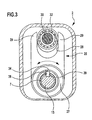
- rocker arms 25, 26 On the bearing sleeve 17 juxtaposed by a spacer ring 24 separately two rocker arms 25, 26 rotatably mounted, these rocker arms have a circular, the bearing sleeve 17 surrounding bearing ring 27 and two parallel, between them a unilaterally open driving opening 28 forming webs 29, which extend on both sides of the drive shaft 5.
- the drive shaft 5 In the region of the rocker arms 25 and 26, the drive shaft 5 each have an eccentric portion 30 and 31, the eccentricity of these eccentric portions 30 and 31 is different, the eccentric portions 30 and 31 are circumferentially offset by 180 ° from each other.
- Each eccentric portion 30, 31 carries a ball bearing 32 and 33, and these ball bearings 32 and 33 engage tightly in the driving openings 28 of the two rocker arms 25 and 26, so that when a rotation of the drive shaft 5, both rocker arms 25, 26 oscillating pivoted back and forth, in accordance with the different eccentricity of the eccentric portions 30 and 31 with different maximum swing angle.
- the tool 16 carries on its shaft 15 a radially projecting driver 39, which enters upon insertion of the shaft 15 in the bearing sleeve 17 in the slot 38 and experiences some guidance in this, the driver 39 occurs during complete insertion of the shaft 15 in the groove 34 or the groove 35 of the two rocker arms 25, 26 a.
- the driver 39 In which of the two grooves 34, 35 of the driver 39 enters, depends on the axial position of the driver 39 on the shaft 15 from.
- the driver 39 is arranged so that when completely inserted shaft 15 of the driver 39 engages in the groove 35 of the rear rocker arm 26, in the embodiment of Figure 2, however, the driver 39 is arranged more towards the front of the tool and thereby enters the groove 34 of the rocker arm 25.
Landscapes
- Health & Medical Sciences (AREA)
- Surgery (AREA)
- Life Sciences & Earth Sciences (AREA)
- Biomedical Technology (AREA)
- Medical Informatics (AREA)
- Orthopedic Medicine & Surgery (AREA)
- Oral & Maxillofacial Surgery (AREA)
- Engineering & Computer Science (AREA)
- Dentistry (AREA)
- Heart & Thoracic Surgery (AREA)
- Nuclear Medicine, Radiotherapy & Molecular Imaging (AREA)
- Molecular Biology (AREA)
- Animal Behavior & Ethology (AREA)
- General Health & Medical Sciences (AREA)
- Public Health (AREA)
- Veterinary Medicine (AREA)
- Surgical Instruments (AREA)
Claims (13)
- Instrument chirurgical (1) avec un outil (16) pouvant pivoter de manière oscillante autour d'un axe de rotation et avec un arbre d'entraînement (5) entraîné en rotation qui, par l'intermédiaire d'un excentrique (30, 31), fait pivoter de manière oscillante dans un sens et dans l'autre un levier oscillant (25, 26) relié à l'outil (16) de manière solidaire en rotation, caractérisé en ce que l'arbre d'entraînement (5) comporte côte à côte au moins deux excentriques (30, 31) d'excentricité différente, qu'à chaque excentrique (30, 31) est associé un levier oscillant (25, 26) pouvant pivoter autour de l'axe de rotation de l'outil (16) et que l'outil (16) n'est relié de manière solidaire en rotation qu'à l'un des deux leviers oscillants (25, 26).
- Instrument selon la revendication 1 caractérisé en ce que différents outils (16) peuvent être reliés de manière solidaire en rotation avec différents leviers oscillants (25, 26).
- Instrument selon la revendication 1 ou 2 caractérisé en ce que l'outil (16) est relié dans une position de travail de manière réversible avec un levier oscillant (25 ou 26) et peut être retiré de l'instrument à partir de cette position de travail.
- Instrument selon la revendication 3 caractérisé en ce que l'outil (16) peut être fixé dans l'instrument dans la position de travail insérée à l'encontre d'un déplacement axial.
- Instrument selon l'une des revendications précédentes caractérisé en ce que la liaison solidaire en rotation est formée par des retraits radiaux coopérants (34, 35) et par des saillies (39) pénétrant dans les précédents et contigus de ceux-ci dans la direction périphérique, qui permet un déplacement axial de l'outil (16) par rapport à l'arbre d'entraînement (5).
- Instrument selon la revendication 5 caractérisé en ce que que la saillie (39) est formée par une nervure parallèle à l'axe en retrait radialement.
- Instrument selon l'une des revendications 5 ou 6 caractérisé en ce que le retrait (34, 35) est formé par une rainure parallèle à l'axe.
- Instrument selon la revendication 7 caractérisé en ce que chaque levier oscillant (25, 26) porte un retrait (34, 35) et en ce que chaque outil (16) ne comporte qu'une saillie (39) qui est agencée en direction axiale le long de l'outil (16) de telle manière qu'elle ne forme une liaison à rotation qu'avec un levier oscillant (25 ou 26).
- Instrument selon l'une des revendications 5 à 8 caractérisé en ce que les saillies et les retraits (34, 35) présentent la même position angulaire sur les leviers oscillants (25, 26).
- Instrument selon la revendication 9 caractérisé en ce qu'il est prévu dans la direction d'insertion de l'outil (16) des moyens de guidage (38) qui se rétrécissent, qui soumettent l'outil (16) à une torsion de telle manière que les saillies (39) et les retraits (34, 35) sont orientés de manière alignée.
- Instrument selon la revendication 10 caractérisé en ce que les moyens de guidage sont formés par une rainure longitudinale (38) qui se rétrécit dans une douille de logement (17) entourant l'outil (16).
- Instrument selon l'une des revendications précédentes caractérisé en ce que les excentriques (30, 31) sont disposés dans une position angulaire différente.
- Instrument selon la revendication 12 caractérisé en ce que, dans le cas de deux excentriques (30, 31), ceux-ci sont décalés en direction opposée.
Applications Claiming Priority (3)
| Application Number | Priority Date | Filing Date | Title |
|---|---|---|---|
| DE10240655 | 2002-09-04 | ||
| DE10240655A DE10240655B3 (de) | 2002-09-04 | 2002-09-04 | Chirurgisches Instrument |
| PCT/EP2003/009664 WO2004021896A1 (fr) | 2002-09-04 | 2003-08-30 | Instrument chirurgical |
Publications (2)
| Publication Number | Publication Date |
|---|---|
| EP1534150A1 EP1534150A1 (fr) | 2005-06-01 |
| EP1534150B1 true EP1534150B1 (fr) | 2006-02-01 |
Family
ID=31969023
Family Applications (1)
| Application Number | Title | Priority Date | Filing Date |
|---|---|---|---|
| EP03793779A Expired - Lifetime EP1534150B1 (fr) | 2002-09-04 | 2003-08-30 | Instrument chirurgical |
Country Status (4)
| Country | Link |
|---|---|
| EP (1) | EP1534150B1 (fr) |
| AU (1) | AU2003258693A1 (fr) |
| DE (1) | DE10240655B3 (fr) |
| WO (1) | WO2004021896A1 (fr) |
Families Citing this family (1)
| Publication number | Priority date | Publication date | Assignee | Title |
|---|---|---|---|---|
| DE102007060493A1 (de) * | 2007-12-05 | 2009-06-10 | Aesculap Ag | Aufsatzvorrichtung für eine chirurgische Vorrichtung sowie chirurgische Vorrichtung zum Durchschneiden eines Knochens |
Family Cites Families (5)
| Publication number | Priority date | Publication date | Assignee | Title |
|---|---|---|---|---|
| FR1441557A (fr) * | 1965-04-01 | 1966-06-10 | Austenal Europa Inc Zweigniede | Moteur universel à main à usage chirurgical |
| US3472081A (en) * | 1967-04-28 | 1969-10-14 | Austenal Europa Inc Zweigniede | Hand motor to drive tools for surgical purposes at different speeds or oscillation frequencies |
| EP0829237A3 (fr) * | 1996-09-12 | 1998-08-12 | Ricana Ag | Appareil de coupe avec outil de coupe sur un essieu moteur oscillant |
| DE19905804C1 (de) * | 1999-02-12 | 2000-02-24 | Aesculap Ag & Co Kg | Verfahren und Vorrichtung zur Zerspanung von Knochenmaterial |
| JP2002102235A (ja) * | 2000-10-02 | 2002-04-09 | Bristol-Myers Squibb Kk | 動力式手術器械 |
-
2002
- 2002-09-04 DE DE10240655A patent/DE10240655B3/de not_active Expired - Fee Related
-
2003
- 2003-08-30 EP EP03793779A patent/EP1534150B1/fr not_active Expired - Lifetime
- 2003-08-30 AU AU2003258693A patent/AU2003258693A1/en not_active Abandoned
- 2003-08-30 WO PCT/EP2003/009664 patent/WO2004021896A1/fr not_active Ceased
Also Published As
| Publication number | Publication date |
|---|---|
| EP1534150A1 (fr) | 2005-06-01 |
| DE10240655B3 (de) | 2004-04-29 |
| WO2004021896A1 (fr) | 2004-03-18 |
| AU2003258693A1 (en) | 2004-03-29 |
Similar Documents
| Publication | Publication Date | Title |
|---|---|---|
| DE19937560B4 (de) | Orbital hin- und hergehende Säge | |
| DE69102579T2 (de) | Kraftwerkzeug. | |
| DE69629895T2 (de) | Schlüsselloser Spannfutter für chirurgisches Blatt | |
| DE102005024370B4 (de) | Antidrehungs-Antriebsmechanismus für Sägen mit Hin- und Herbewegung | |
| DE3711377C2 (de) | Chirurgisches Instrument | |
| EP3528688A1 (fr) | Dispositif médical | |
| DE102006041430B4 (de) | Werkzeugmaschine mit Motorantrieb | |
| EP0142611B1 (fr) | Outil de perçage pour usiner des surfaces de détalonnage dans des perçages préfabriqués | |
| EP1694477B1 (fr) | Dispositif d'accouplement | |
| EP1163980B1 (fr) | Outil portatif | |
| DE4330728A1 (de) | Zweifach-Werkzeugträger für Handbohrmaschinen | |
| WO2002032342A1 (fr) | Brosse a dents electrique | |
| DE602004012977T2 (de) | Kraftwerkzeug mit einem Betriebsartauswahlmechanismus | |
| EP1621294B1 (fr) | Manche d'outil | |
| DE4445677A1 (de) | Schlagbohrmaschineneinstellmechanik | |
| DE8304917U1 (de) | Bohrmaschine | |
| EP2655018A1 (fr) | Machine-outil à main | |
| EP1534150B1 (fr) | Instrument chirurgical | |
| DE3500445C2 (fr) | ||
| EP0293654A2 (fr) | Appareil à détartrer les dents | |
| DE20213571U1 (de) | Chirurgisches Instrument | |
| EP1627611B1 (fr) | Tête pour une pièce à main médicale de transmission d'un mouvement va-et-vient à un outil de traitement | |
| EP2621700A1 (fr) | Dispositif de coupe pour un granulateur permettant d'obtenir des granulés par découpe de joncs de matière plastique sortant de filières et doté d'un rotor à lames | |
| EP1459857B1 (fr) | Outil à main avec protection ajustable pour fraise circulaire | |
| EP0218831B1 (fr) | Entraînement pour un outil oscillant |
Legal Events
| Date | Code | Title | Description |
|---|---|---|---|
| PUAI | Public reference made under article 153(3) epc to a published international application that has entered the european phase |
Free format text: ORIGINAL CODE: 0009012 |
|
| 17P | Request for examination filed |
Effective date: 20041221 |
|
| AK | Designated contracting states |
Kind code of ref document: A1 Designated state(s): AT BE BG CH CY CZ DE DK EE ES FI FR GB GR HU IE IT LI LU MC NL PT RO SE SI SK TR |
|
| AX | Request for extension of the european patent |
Extension state: AL LT LV MK |
|
| GRAP | Despatch of communication of intention to grant a patent |
Free format text: ORIGINAL CODE: EPIDOSNIGR1 |
|
| RBV | Designated contracting states (corrected) |
Designated state(s): FR GB |
|
| REG | Reference to a national code |
Ref country code: DE Ref legal event code: 8566 |
|
| GRAS | Grant fee paid |
Free format text: ORIGINAL CODE: EPIDOSNIGR3 |
|
| GRAA | (expected) grant |
Free format text: ORIGINAL CODE: 0009210 |
|
| DAX | Request for extension of the european patent (deleted) | ||
| AK | Designated contracting states |
Kind code of ref document: B1 Designated state(s): FR GB |
|
| REG | Reference to a national code |
Ref country code: GB Ref legal event code: FG4D Free format text: NOT ENGLISH |
|
| GBT | Gb: translation of ep patent filed (gb section 77(6)(a)/1977) |
Effective date: 20060329 |
|
| ET | Fr: translation filed | ||
| PLBE | No opposition filed within time limit |
Free format text: ORIGINAL CODE: 0009261 |
|
| STAA | Information on the status of an ep patent application or granted ep patent |
Free format text: STATUS: NO OPPOSITION FILED WITHIN TIME LIMIT |
|
| 26N | No opposition filed |
Effective date: 20061103 |
|
| PGFP | Annual fee paid to national office [announced via postgrant information from national office to epo] |
Ref country code: FR Payment date: 20140819 Year of fee payment: 12 Ref country code: GB Payment date: 20140821 Year of fee payment: 12 |
|
| GBPC | Gb: european patent ceased through non-payment of renewal fee |
Effective date: 20150830 |
|
| REG | Reference to a national code |
Ref country code: FR Ref legal event code: ST Effective date: 20160429 |
|
| PG25 | Lapsed in a contracting state [announced via postgrant information from national office to epo] |
Ref country code: GB Free format text: LAPSE BECAUSE OF NON-PAYMENT OF DUE FEES Effective date: 20150830 |
|
| PG25 | Lapsed in a contracting state [announced via postgrant information from national office to epo] |
Ref country code: FR Free format text: LAPSE BECAUSE OF NON-PAYMENT OF DUE FEES Effective date: 20150831 |