EP1535523A2 - Dispositifs et procédé pour la separation de tabac d'une bale de tabac - Google Patents
Dispositifs et procédé pour la separation de tabac d'une bale de tabac Download PDFInfo
- Publication number
- EP1535523A2 EP1535523A2 EP04090463A EP04090463A EP1535523A2 EP 1535523 A2 EP1535523 A2 EP 1535523A2 EP 04090463 A EP04090463 A EP 04090463A EP 04090463 A EP04090463 A EP 04090463A EP 1535523 A2 EP1535523 A2 EP 1535523A2
- Authority
- EP
- European Patent Office
- Prior art keywords
- separating
- drive
- tobacco
- drives
- knife
- Prior art date
- Legal status (The legal status is an assumption and is not a legal conclusion. Google has not performed a legal analysis and makes no representation as to the accuracy of the status listed.)
- Granted
Links
Images


Classifications
-
- A—HUMAN NECESSITIES
- A24—TOBACCO; CIGARS; CIGARETTES; SIMULATED SMOKING DEVICES; SMOKERS' REQUISITES
- A24B—MANUFACTURE OR PREPARATION OF TOBACCO FOR SMOKING OR CHEWING; TOBACCO; SNUFF
- A24B7/00—Cutting tobacco
- A24B7/04—Cutting tobacco by machines with revolving knives
- A24B7/08—Cutting tobacco by machines with revolving knives with several knives which act one after the other
- A24B7/12—Cutting tobacco by machines with revolving knives with several knives which act one after the other with cutter axes transverse to the feeding direction
Definitions
- the invention relates to a device for separating tobacco from a Tobacco cake comprising a rotationally drivable release agent with at least one Separating element, and a drive for driving the release agent.
- the invention further relates to a device for separating tobacco from a tobacco cake, comprising a rotationally drivable release agent with at least one separating element, and a plurality of drives, wherein a first drive for driving the release agent and a second drive for moving the separating element is used.
- the Invention a method for separating tobacco from a tobacco cake, comprising the steps: feeding the tobacco cake to at least one separating element having release agent, and driving the release agent to separate the tobacco from the tobacco cake through each separator.
- Such devices that are part of a so-called tobacco cutter come especially in the tobacco processing industry in cigarette manufacturing for Commitment.
- the device is for separating tobacco and / or ribs or else suitable for other products. This is a previously formed from compressed tobacco Tobacco cake from a compressor led to the cutting device.
- the Cutting device then portioned by rotation of the release agent with the Separators the tobacco cake. This also leads to wear of the separating elements, why they are advanced continuously or intermittently to the Compensate for wear. When fully worn, the dividing elements must be replaced.
- the drive is an electromechanical direct drive.
- the inventive design is achieved a particularly compact design, as on a variety of components can be dispensed with.
- the drive can be easily encapsulated, so that the Noise pollution is reduced by the drive.
- the reduction of components and Components leads at the same time to a reduced maintenance and Cleaning effort.
- Another advantage is that the to be transmitted Moment exclusively depends on the drive. Slippage between the drive and the Release agent is thereby avoided.
- the direct drive is a torque motor, the direct and immediate the separating means is coupled, wherein the torque motor as a bearing-free hollow shaft motor is trained.
- the torque motor as a bearing-free hollow shaft motor is trained.
- a stator of the drive is stationary arranged on an axis while a corresponding rotor of the drive via a hub is connected to the release agent.
- stator and the rotor are in arranged a recess of the hub, creating a particularly compact and rigid Arrangement is achieved.
- the object is achieved by a device which thereby is characterized in that at least one of the two drives as electromechanical Direct drive is formed. This is a simple and compact design of Device guaranteed.
- both drives are designed as electromechanical direct drives, wherein the second direct drive for synchronously advancing or retracting all Separating elements or of separating knives, which are part of the separating elements, is trained. This enables a particularly effective and simple way Continuous adjustment of the cutting blades in online operation.
- the second direct drive is directly and directly to a Ring gear coupled, which is movable relative to the release agent. This makes it possible depending on customer wishes or production or operating requirements, one Stepless and exact adjustment of the synchronous movement of all cutting blades reach, online.
- each separating element in addition to the Cutting knife a knife holder, liners, one held in the liners Bridge, spindles on which the liners are movable, guide rails as well Transmission elements and a drive pinion, wherein the sprocket each in Engage with the drive pinion of each separator.
- the object is also achieved by a method with the steps mentioned above achieved in that the release agent with the or each separator directly through an electromechanical direct drive is driven.
- the torque to be transmitted depends exclusively on the direct drive, as on Transmission links can be dispensed with.
- the method allows one slip-free drive of the release agent, whereby an exact adjustment of Ensures separating elements or the separating knife as part of the separating elements is.
- the rotational movement of the release agent a rotational movement of a ring gear for moving the separating elements or of Overlaid cutting blades.
- a continuous adjustment of the separating elements or the cutting knife allows.
- the method ensures a high adjustment range of the separating elements or the separating knife.
- the devices shown and the described method for separating Tobacco from the tobacco cake is used in the production of cigarettes or the like for use.
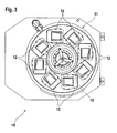
- FIG. 1 shows a device 10 for separating tobacco from one Tobacco cake.
- the device 10 is part of a tobacco cutter and has a Release agent 11 with at least one separating element 12 and a drive 13.
- the release agent 11 is a cutting plate 14
- Am Cutting plates 14 are several, preferably eight evenly and concentrically around the Rotary axis 15 arranged separating elements 12 are arranged. The number and location of However, dividers 12 may vary. Also, the release agent 11 may alternatively as Cutting drum to be formed.
- the drive 13 is an electromechanical direct drive.
- the direct drive is as Torque motor formed and connected directly to the cutting plate 14 or at attached to this.
- the torque motor is designed as a hollow shaft motor, the self is stock-free.
- the torque motor is within a concentric about the axis of rotation 15th extending recess 16 of a hub 17, wherein the hub 17 by means of usual bearing 18, e.g. Ball bearing, rotatably mounted on a stationary shaft 19 is.
- the axis 19 is hollow, so that they as a cable gland or can serve the same.
- the torque motor comprises a stator 20 and a rotor 21.
- the stator 20 is fixed to the axis 19 is arranged.
- the stator 20 on a flange, as Washer 22 is formed, attached, which in turn in the region of the hub 17 on the the cutting plate 14 facing side is arranged.
- the annular disc 22 serves the Stator 20 also as a centering and is on a cover 23, which serves as a base plate is formed, fastened,
- the interior of the hub 17 is by means of a labyrinth seal sealed against the base plate.
- the rotor 21 is fixed to the hub 17th connected so that a rotational movement of the rotor 21 directly and directly on the Hub 17 is transferable.
- the rotor 21 is clutch-free directly and stiffly over the hub 17 connected to the cutting plate 14.
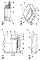
- the device 10 has two drives, namely the drive 13 for driving the Separating means 11 and a drive 24 for moving separating blades 35, which as Knife blades are part of the separating elements 12.
- Both drives 13, 24 are as Direct drives trained as a torque motors.
- drive 24 can also be conventional indirect drive can be used. Other standard direct drives However, they are also usable.
- the drives 13, 24 are preferably in succession the same axis 19, arranged. Alternatively, however, each drive 13, 24 on be arranged on its own axis.
- the drives 13, 24 are separately controllable, so that a differential speed is adjustable. However, the drives 13, 24 at a common (not shown) control and / or regulating unit be connected on the one hand to set a desired differential speed or on the other hand, to synchronize the drives 13, 24.
- the drive 13 is designed and arranged according to the above description, so that a renewed description is omitted.
- the drive 24 is used for Driving a ring gear 25 or the like, in operative connection with the Separating elements 12 is.
- the ring gear 25 extends concentrically about the axis of rotation 15th and is fixedly connected to a cylindrical member 26, which via the hub 17th is slipped.
- the element 26 is designed to be movable relative to the hub 17 and arranged.
- the drive 24 also includes a stator 27 and a rotor 28.
- the stator 27 is firmly arranged on a support element 29.
- the support member 29 is fixed and non-rotatable attached to the axle 19.
- the rotor 28 is fixedly connected to the element 26, thus, that a rotation of the rotor 28 to a rotation of the element 26 and thus of the Sprocket 25 leads.
- the element 26 is rotatable by means of conventional bearings 30, e.g. Ball bearing, mounted on the axle 19.
- Preferably in the region of the axis 19 are Rotary encoder 31, 32 arranged by means of which the rotational speed or the rotational angle position of the Drives 13, 24 can be detected.
- a first rotary encoder 31 is on the one hand on the axis 19th arranged and detected via a rotational position transfer frame 50, the rotational angle position of the drive 24.
- the second rotary encoder 32 is on the cover 23, as Base plate is formed, mounted and detected by a pinion the Rotation angle position of the hub 17 and thus that of the drive 13th
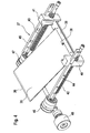
- the separating elements 12 are detachably connected arranged the cutting plate 14.
- Each separating element 12 has a housing 33. Within the housing 33, the at least by means of a removable cover 34th is accessible, the actual separating knife 35 is arranged.
- the plate-like Cutting knife 35 is radially aligned with its cutting edge 36 and releasably connected to a Knife holder 37 is arranged.
- the separating knife 35 is preferably for this purpose with at least one screw 38, a snap or the like on a web 39 attached.
- the web 39 is fixed but detachable at opposite ends Bushings 40, 41 held, wherein the liners 40, 41 on the one hand on one Spindle 42, 43, namely a so-called feed screw, arranged movable are. On the other hand, the liners 40, 41 guided on guide rails 44, 45.
- the guide rails 44, 45 are parallel to each other and are on the housing 33rd attached.
- the separating knife 35 is inclined inside arranged the housing 33, such that the separating knife 35, starting from the web 39, on which the cutting knife 35 is fixed, with respect to the spindles 42, 43 obliquely goes up.
- the spindles 42, 43 are on the cutting edge 36 side facing with a Transmission element 46, 47 provided, each for transmitting the rotation of a Drive pinion 48 on the spindles 42, 43 are formed.
- the drive pinion 48 is meshing with the ring gear 25.
- Extending movement means in this Context, that the separating knife 35 in the direction of a (not shown) Move grinding device.
- the liners 40, 41 from their in Figure 4 shown starting position in the direction of the transmission elements 46, 47 movable, so that the cutting knife 35 is thereby advanceable.
- the speed of the Drive 24 higher than the speed of the drive 13, this causes Retracting the separating knife 35 in the opposite direction.
- Words determines the phase position of the drives 13, 24, the position of the separating knife 35th Alternatively, however, other common drive mechanisms for transmission the rotation of the ring gear 25 in a linear movement of the cutting blade 35th used.
- the release agent 11, which carries a plurality of separating elements 12, is directly driven by the first drive 13.
- the hub 17, which transmits the torque from the rotor 21 to the cutting plate 14 is mounted on the axis 19 and thus absorbs the tilting moments and axial forces.
- the advantages of this method are that the moments that can be transmitted depend exclusively on the drive 13. On a lower or translation can be omitted, since the cutting plate speed corresponds to the drive speed.
- the movement of the separating blade 35 is achieved in that the drive 13 the Rotation of the cutting plate 14 and the drive 24, the rotation of the ring gear 25th realized with respect to the cutting plate 14.
- the spindles 42, 43 By the rotation of the ring gear 25 opposite the cutting plate 14, the spindles 42, 43 in a rotary motion added.
- the differential speed between the drive 13 and the drive 24th becomes the movement, namely the advance or retraction of the cutting knife 35th certainly.
- This method thus enables a central and synchronous movement the separating knife 35.
- the required differential speed is very low, so that the Drives 13, 24 run almost synchronously.
- the rotational speeds of the cutting plate 14 and the ring gear 25 are each directly from the rotor 21 and 28 of the drive 13 and 24 in the corresponding Function unit, namely once the unit for driving the cutting plate 14 and on the other hand, the unit for driving the cutting blade 35, initiated.
Landscapes
- Manufacturing Of Cigar And Cigarette Tobacco (AREA)
- Manufacture Of Tobacco Products (AREA)
- Connection Of Motors, Electrical Generators, Mechanical Devices, And The Like (AREA)
- Retarders (AREA)
Priority Applications (1)
| Application Number | Priority Date | Filing Date | Title |
|---|---|---|---|
| PL04090463T PL1535523T3 (pl) | 2003-11-25 | 2004-11-25 | Urządzenie i sposób cięcia tytoniu z placka tytoniowego |
Applications Claiming Priority (2)
| Application Number | Priority Date | Filing Date | Title |
|---|---|---|---|
| DE10355874A DE10355874A1 (de) | 2003-11-25 | 2003-11-25 | Vorrichtungen und Verfahren zum Trennen von Tabak von einem Tabakkuchen |
| DE10355874 | 2003-11-25 |
Publications (3)
| Publication Number | Publication Date |
|---|---|
| EP1535523A2 true EP1535523A2 (fr) | 2005-06-01 |
| EP1535523A3 EP1535523A3 (fr) | 2005-06-08 |
| EP1535523B1 EP1535523B1 (fr) | 2007-11-14 |
Family
ID=34442357
Family Applications (1)
| Application Number | Title | Priority Date | Filing Date |
|---|---|---|---|
| EP04090463A Expired - Lifetime EP1535523B1 (fr) | 2003-11-25 | 2004-11-25 | Dispositifs et procédé pour la separation de tabac d'une bale de tabac |
Country Status (6)
| Country | Link |
|---|---|
| EP (1) | EP1535523B1 (fr) |
| JP (1) | JP2005160478A (fr) |
| CN (1) | CN100584226C (fr) |
| AT (1) | ATE377966T1 (fr) |
| DE (2) | DE10355874A1 (fr) |
| PL (1) | PL1535523T3 (fr) |
Family Cites Families (9)
| Publication number | Priority date | Publication date | Assignee | Title |
|---|---|---|---|---|
| US2835299A (en) * | 1953-02-16 | 1958-05-20 | Koerber & Co Kg | Removable drum type tobacco cutting machine with fixed grinding means |
| GB750639A (en) * | 1953-02-16 | 1956-06-20 | Kurt Koerber | Improvements in tobacco cutting machines |
| DE966859C (de) * | 1953-06-28 | 1957-09-12 | Und Eisengiesserei A Heinen G | Tabakschneidmaschine |
| DE961337C (de) * | 1954-07-13 | 1957-04-04 | Wilh Quester Maschinenfabrik | Schneidmaschine fuer Tabak, Textilfasern u. dgl. |
| GB2105578B (en) * | 1981-07-14 | 1985-02-06 | Sagemueller Franz Gmbh | Apparatus for cutting plant materials in particular tobacco |
| DE8625194U1 (de) * | 1986-09-20 | 1988-01-21 | Robert Bosch Gmbh, 7000 Stuttgart | Elektrische Maschine, insbesondere elektrischer Motor |
| DE10021614A1 (de) * | 2000-05-04 | 2001-11-08 | Hauni Maschinenbau Ag | Verfahren und Vorrichtung zum automatischen Nachschleifen von Tabakschneidemessern |
| FR2811034A1 (fr) * | 2000-06-29 | 2002-01-04 | Technofan | Ventilateur a moteur axial |
| PL204715B1 (pl) * | 2002-05-08 | 2010-02-26 | Int Tobacco Machinery Poland | Krajarka do materiałów pochodzenia roślinnego, zwłaszcza do tytoniu |
-
2003
- 2003-11-25 DE DE10355874A patent/DE10355874A1/de not_active Ceased
-
2004
- 2004-11-24 JP JP2004338248A patent/JP2005160478A/ja not_active Withdrawn
- 2004-11-25 PL PL04090463T patent/PL1535523T3/pl unknown
- 2004-11-25 EP EP04090463A patent/EP1535523B1/fr not_active Expired - Lifetime
- 2004-11-25 AT AT04090463T patent/ATE377966T1/de not_active IP Right Cessation
- 2004-11-25 CN CN200410096202A patent/CN100584226C/zh not_active Expired - Fee Related
- 2004-11-25 DE DE502004005485T patent/DE502004005485D1/de not_active Expired - Lifetime
Also Published As
| Publication number | Publication date |
|---|---|
| CN1620944A (zh) | 2005-06-01 |
| EP1535523A3 (fr) | 2005-06-08 |
| JP2005160478A (ja) | 2005-06-23 |
| DE502004005485D1 (de) | 2007-12-27 |
| DE10355874A1 (de) | 2005-06-30 |
| PL1535523T3 (pl) | 2008-02-29 |
| DE10355874A8 (de) | 2006-06-01 |
| EP1535523B1 (fr) | 2007-11-14 |
| CN100584226C (zh) | 2010-01-27 |
| ATE377966T1 (de) | 2007-11-15 |
Similar Documents
| Publication | Publication Date | Title |
|---|---|---|
| EP2258522B1 (fr) | Procédé et dispositif pour couper une tige guidée continûment dans des articles en forme de tige | |
| DE3784270T2 (de) | Rotationsstanze und ihr getriebe. | |
| EP0527317B1 (fr) | Dispositif de sortie dans la plieuse d'une rotative | |
| EP2329931A1 (fr) | Dispositif de découpage de produits alimentaires | |
| DE3416664C2 (de) | Einrichtung zum Steuern der Schneidgeschwindigkeit des Sägeblattes einer Bandsägemaschine | |
| DE3934673C2 (fr) | ||
| EP0302489B1 (fr) | Dispositif à plier | |
| DE102018004651A1 (de) | Trennmaschine | |
| DE1511269B1 (de) | Vorrichtung zum radialen Schneiden rollenfoermiger Koerper | |
| DE2921665A1 (de) | Vorrichtung zum selbsttaetigen vorschub von schneidmessern an tabakschneidmaschinen | |
| DE60317713T2 (de) | Schneidemaschine für organisches pflanzenmaterial, insbesondere für tabak | |
| DE102012207304A1 (de) | Antriebsvorrichtung | |
| WO2003072477A1 (fr) | Appareils de pliage | |
| EP1099502B1 (fr) | Cisaille volante pour couper des bandes métalliques | |
| DE2931970C2 (de) | Schneidvorrichtung zum Längsschneiden einer Papierbahn | |
| DE4114341C2 (de) | Maschine zur Bearbeitung umlaufender Werkstücke mittels eines in bestimmtem Drehzahlverhältnis synchron dazu umlaufenden Werkzeugs | |
| EP1535523B1 (fr) | Dispositifs et procédé pour la separation de tabac d'une bale de tabac | |
| DE3423275A1 (de) | Vorrichtung zur einstellung des messerspaltes an trommelscheren | |
| EP1594663A1 (fr) | Dispositif de decoupage dans le sens de la longueur pour decouper des bandes de matieres en mouvement | |
| DE2607901A1 (de) | Umlaufender werkzeugkopf fuer schaelmaschinen | |
| DE2908925C2 (de) | Pelzschneidevorrichtung | |
| EP0456962B1 (fr) | Dispositif pour vider la matrice d'une extrudeuse pour le traitement de matières céramiques | |
| DE1045638B (de) | Vorrichtung zum fortlaufenden Schneiden von Baendern, Streifen und Faeden aus Zylindern aus elastischem Material, wie Schaumkunststoffen, Kork od. dgl. | |
| DE2053948A1 (en) | Bale opener - with rotary cutting units to process series of bales arranged in a circle | |
| DE486386C (de) | Schere zum Schneiden breiter Streifen laufenden Walzgutes mit an zwei sich gegenlaeufig drehenden Traegern angeordneten umlaufenden Messern |
Legal Events
| Date | Code | Title | Description |
|---|---|---|---|
| PUAI | Public reference made under article 153(3) epc to a published international application that has entered the european phase |
Free format text: ORIGINAL CODE: 0009012 |
|
| PUAL | Search report despatched |
Free format text: ORIGINAL CODE: 0009013 |
|
| AK | Designated contracting states |
Kind code of ref document: A2 Designated state(s): AT BE BG CH CY CZ DE DK EE ES FI FR GB GR HU IE IS IT LI LU MC NL PL PT RO SE SI SK TR |
|
| AX | Request for extension of the european patent |
Extension state: AL HR LT LV MK YU |
|
| AK | Designated contracting states |
Kind code of ref document: A3 Designated state(s): AT BE BG CH CY CZ DE DK EE ES FI FR GB GR HU IE IS IT LI LU MC NL PL PT RO SE SI SK TR |
|
| AX | Request for extension of the european patent |
Extension state: AL HR LT LV MK YU |
|
| 17P | Request for examination filed |
Effective date: 20051203 |
|
| AKX | Designation fees paid |
Designated state(s): AT BE BG CH CY CZ DE DK EE ES FI FR GB GR HU IE IS IT LI LU MC NL PL PT RO SE SI SK TR |
|
| RAP1 | Party data changed (applicant data changed or rights of an application transferred) |
Owner name: HAUNI PRIMARY GMBH |
|
| RAP1 | Party data changed (applicant data changed or rights of an application transferred) |
Owner name: HAUNI PRIMARY GMBH |
|
| 17Q | First examination report despatched |
Effective date: 20061005 |
|
| GRAP | Despatch of communication of intention to grant a patent |
Free format text: ORIGINAL CODE: EPIDOSNIGR1 |
|
| GRAS | Grant fee paid |
Free format text: ORIGINAL CODE: EPIDOSNIGR3 |
|
| GRAA | (expected) grant |
Free format text: ORIGINAL CODE: 0009210 |
|
| AK | Designated contracting states |
Kind code of ref document: B1 Designated state(s): AT BE BG CH CY CZ DE DK EE ES FI FR GB GR HU IE IS IT LI LU MC NL PL PT RO SE SI SK TR |
|
| REG | Reference to a national code |
Ref country code: GB Ref legal event code: FG4D Free format text: NOT ENGLISH |
|
| REG | Reference to a national code |
Ref country code: CH Ref legal event code: EP |
|
| REG | Reference to a national code |
Ref country code: IE Ref legal event code: FG4D Free format text: LANGUAGE OF EP DOCUMENT: GERMAN |
|
| REF | Corresponds to: |
Ref document number: 502004005485 Country of ref document: DE Date of ref document: 20071227 Kind code of ref document: P |
|
| REG | Reference to a national code |
Ref country code: PL Ref legal event code: T3 |
|
| PG25 | Lapsed in a contracting state [announced via postgrant information from national office to epo] |
Ref country code: SE Free format text: LAPSE BECAUSE OF FAILURE TO SUBMIT A TRANSLATION OF THE DESCRIPTION OR TO PAY THE FEE WITHIN THE PRESCRIBED TIME-LIMIT Effective date: 20080214 Ref country code: ES Free format text: LAPSE BECAUSE OF FAILURE TO SUBMIT A TRANSLATION OF THE DESCRIPTION OR TO PAY THE FEE WITHIN THE PRESCRIBED TIME-LIMIT Effective date: 20080225 |
|
| PG25 | Lapsed in a contracting state [announced via postgrant information from national office to epo] |
Ref country code: BG Free format text: LAPSE BECAUSE OF FAILURE TO SUBMIT A TRANSLATION OF THE DESCRIPTION OR TO PAY THE FEE WITHIN THE PRESCRIBED TIME-LIMIT Effective date: 20080214 Ref country code: FI Free format text: LAPSE BECAUSE OF FAILURE TO SUBMIT A TRANSLATION OF THE DESCRIPTION OR TO PAY THE FEE WITHIN THE PRESCRIBED TIME-LIMIT Effective date: 20071114 Ref country code: SI Free format text: LAPSE BECAUSE OF FAILURE TO SUBMIT A TRANSLATION OF THE DESCRIPTION OR TO PAY THE FEE WITHIN THE PRESCRIBED TIME-LIMIT Effective date: 20071114 Ref country code: IS Free format text: LAPSE BECAUSE OF FAILURE TO SUBMIT A TRANSLATION OF THE DESCRIPTION OR TO PAY THE FEE WITHIN THE PRESCRIBED TIME-LIMIT Effective date: 20080314 |
|
| BERE | Be: lapsed |
Owner name: HAUNI PRIMARY G.M.B.H. Effective date: 20071130 |
|
| PG25 | Lapsed in a contracting state [announced via postgrant information from national office to epo] |
Ref country code: MC Free format text: LAPSE BECAUSE OF NON-PAYMENT OF DUE FEES Effective date: 20071130 |
|
| PG25 | Lapsed in a contracting state [announced via postgrant information from national office to epo] |
Ref country code: CZ Free format text: LAPSE BECAUSE OF FAILURE TO SUBMIT A TRANSLATION OF THE DESCRIPTION OR TO PAY THE FEE WITHIN THE PRESCRIBED TIME-LIMIT Effective date: 20071114 Ref country code: DK Free format text: LAPSE BECAUSE OF FAILURE TO SUBMIT A TRANSLATION OF THE DESCRIPTION OR TO PAY THE FEE WITHIN THE PRESCRIBED TIME-LIMIT Effective date: 20071114 |
|
| EN | Fr: translation not filed | ||
| PG25 | Lapsed in a contracting state [announced via postgrant information from national office to epo] |
Ref country code: RO Free format text: LAPSE BECAUSE OF FAILURE TO SUBMIT A TRANSLATION OF THE DESCRIPTION OR TO PAY THE FEE WITHIN THE PRESCRIBED TIME-LIMIT Effective date: 20071114 Ref country code: SK Free format text: LAPSE BECAUSE OF FAILURE TO SUBMIT A TRANSLATION OF THE DESCRIPTION OR TO PAY THE FEE WITHIN THE PRESCRIBED TIME-LIMIT Effective date: 20071114 |
|
| PLBE | No opposition filed within time limit |
Free format text: ORIGINAL CODE: 0009261 |
|
| STAA | Information on the status of an ep patent application or granted ep patent |
Free format text: STATUS: NO OPPOSITION FILED WITHIN TIME LIMIT |
|
| PG25 | Lapsed in a contracting state [announced via postgrant information from national office to epo] |
Ref country code: BE Free format text: LAPSE BECAUSE OF NON-PAYMENT OF DUE FEES Effective date: 20071130 Ref country code: PT Free format text: LAPSE BECAUSE OF FAILURE TO SUBMIT A TRANSLATION OF THE DESCRIPTION OR TO PAY THE FEE WITHIN THE PRESCRIBED TIME-LIMIT Effective date: 20080414 |
|
| 26N | No opposition filed |
Effective date: 20080815 |
|
| PG25 | Lapsed in a contracting state [announced via postgrant information from national office to epo] |
Ref country code: FR Free format text: LAPSE BECAUSE OF FAILURE TO SUBMIT A TRANSLATION OF THE DESCRIPTION OR TO PAY THE FEE WITHIN THE PRESCRIBED TIME-LIMIT Effective date: 20080829 Ref country code: IE Free format text: LAPSE BECAUSE OF NON-PAYMENT OF DUE FEES Effective date: 20071126 |
|
| PG25 | Lapsed in a contracting state [announced via postgrant information from national office to epo] |
Ref country code: GR Free format text: LAPSE BECAUSE OF FAILURE TO SUBMIT A TRANSLATION OF THE DESCRIPTION OR TO PAY THE FEE WITHIN THE PRESCRIBED TIME-LIMIT Effective date: 20080215 Ref country code: EE Free format text: LAPSE BECAUSE OF FAILURE TO SUBMIT A TRANSLATION OF THE DESCRIPTION OR TO PAY THE FEE WITHIN THE PRESCRIBED TIME-LIMIT Effective date: 20071114 |
|
| PG25 | Lapsed in a contracting state [announced via postgrant information from national office to epo] |
Ref country code: AT Free format text: LAPSE BECAUSE OF NON-PAYMENT OF DUE FEES Effective date: 20071125 |
|
| REG | Reference to a national code |
Ref country code: CH Ref legal event code: PL |
|
| PG25 | Lapsed in a contracting state [announced via postgrant information from national office to epo] |
Ref country code: CY Free format text: LAPSE BECAUSE OF FAILURE TO SUBMIT A TRANSLATION OF THE DESCRIPTION OR TO PAY THE FEE WITHIN THE PRESCRIBED TIME-LIMIT Effective date: 20071114 |
|
| PG25 | Lapsed in a contracting state [announced via postgrant information from national office to epo] |
Ref country code: LU Free format text: LAPSE BECAUSE OF NON-PAYMENT OF DUE FEES Effective date: 20071125 |
|
| PG25 | Lapsed in a contracting state [announced via postgrant information from national office to epo] |
Ref country code: TR Free format text: LAPSE BECAUSE OF FAILURE TO SUBMIT A TRANSLATION OF THE DESCRIPTION OR TO PAY THE FEE WITHIN THE PRESCRIBED TIME-LIMIT Effective date: 20071114 Ref country code: HU Free format text: LAPSE BECAUSE OF FAILURE TO SUBMIT A TRANSLATION OF THE DESCRIPTION OR TO PAY THE FEE WITHIN THE PRESCRIBED TIME-LIMIT Effective date: 20080515 |
|
| PG25 | Lapsed in a contracting state [announced via postgrant information from national office to epo] |
Ref country code: LI Free format text: LAPSE BECAUSE OF NON-PAYMENT OF DUE FEES Effective date: 20081130 Ref country code: CH Free format text: LAPSE BECAUSE OF NON-PAYMENT OF DUE FEES Effective date: 20081130 |
|
| PGFP | Annual fee paid to national office [announced via postgrant information from national office to epo] |
Ref country code: GB Payment date: 20151123 Year of fee payment: 12 |
|
| GBPC | Gb: european patent ceased through non-payment of renewal fee |
Effective date: 20161125 |
|
| PG25 | Lapsed in a contracting state [announced via postgrant information from national office to epo] |
Ref country code: GB Free format text: LAPSE BECAUSE OF NON-PAYMENT OF DUE FEES Effective date: 20161125 |
|
| PGFP | Annual fee paid to national office [announced via postgrant information from national office to epo] |
Ref country code: DE Payment date: 20191128 Year of fee payment: 16 Ref country code: NL Payment date: 20191122 Year of fee payment: 16 |
|
| PGFP | Annual fee paid to national office [announced via postgrant information from national office to epo] |
Ref country code: PL Payment date: 20191024 Year of fee payment: 16 Ref country code: IT Payment date: 20191129 Year of fee payment: 16 |
|
| REG | Reference to a national code |
Ref country code: DE Ref legal event code: R119 Ref document number: 502004005485 Country of ref document: DE |
|
| REG | Reference to a national code |
Ref country code: NL Ref legal event code: MM Effective date: 20201201 |
|
| PG25 | Lapsed in a contracting state [announced via postgrant information from national office to epo] |
Ref country code: NL Free format text: LAPSE BECAUSE OF NON-PAYMENT OF DUE FEES Effective date: 20201201 |
|
| PG25 | Lapsed in a contracting state [announced via postgrant information from national office to epo] |
Ref country code: IT Free format text: LAPSE BECAUSE OF NON-PAYMENT OF DUE FEES Effective date: 20201125 |
|
| PG25 | Lapsed in a contracting state [announced via postgrant information from national office to epo] |
Ref country code: DE Free format text: LAPSE BECAUSE OF NON-PAYMENT OF DUE FEES Effective date: 20210601 |
|
| PG25 | Lapsed in a contracting state [announced via postgrant information from national office to epo] |
Ref country code: PL Free format text: LAPSE BECAUSE OF NON-PAYMENT OF DUE FEES Effective date: 20201125 |