EP1536033B1 - Dépôt en phase vapeur - Google Patents
Dépôt en phase vapeur Download PDFInfo
- Publication number
- EP1536033B1 EP1536033B1 EP03027389A EP03027389A EP1536033B1 EP 1536033 B1 EP1536033 B1 EP 1536033B1 EP 03027389 A EP03027389 A EP 03027389A EP 03027389 A EP03027389 A EP 03027389A EP 1536033 B1 EP1536033 B1 EP 1536033B1
- Authority
- EP
- European Patent Office
- Prior art keywords
- component
- coating
- turbine
- process according
- activator
- Prior art date
- Legal status (The legal status is an assumption and is not a legal conclusion. Google has not performed a legal analysis and makes no representation as to the accuracy of the status listed.)
- Expired - Lifetime
Links
- 238000001947 vapour-phase growth Methods 0.000 title 1
- 238000000576 coating method Methods 0.000 claims description 41
- 238000000034 method Methods 0.000 claims description 41
- 239000011248 coating agent Substances 0.000 claims description 25
- 239000000463 material Substances 0.000 claims description 18
- PXHVJJICTQNCMI-UHFFFAOYSA-N Nickel Chemical compound [Ni] PXHVJJICTQNCMI-UHFFFAOYSA-N 0.000 claims description 11
- 239000012190 activator Substances 0.000 claims description 11
- XAGFODPZIPBFFR-UHFFFAOYSA-N aluminium Chemical compound [Al] XAGFODPZIPBFFR-UHFFFAOYSA-N 0.000 claims description 11
- 229910052782 aluminium Inorganic materials 0.000 claims description 10
- 238000006243 chemical reaction Methods 0.000 claims description 9
- 239000003795 chemical substances by application Substances 0.000 claims description 9
- 239000010941 cobalt Substances 0.000 claims description 9
- GUTLYIVDDKVIGB-UHFFFAOYSA-N cobalt atom Chemical compound [Co] GUTLYIVDDKVIGB-UHFFFAOYSA-N 0.000 claims description 9
- 229910017052 cobalt Inorganic materials 0.000 claims description 8
- 238000002485 combustion reaction Methods 0.000 claims description 7
- 229910052751 metal Inorganic materials 0.000 claims description 6
- 239000002184 metal Substances 0.000 claims description 6
- VYZAMTAEIAYCRO-UHFFFAOYSA-N Chromium Chemical compound [Cr] VYZAMTAEIAYCRO-UHFFFAOYSA-N 0.000 claims description 5
- 239000011651 chromium Substances 0.000 claims description 5
- 238000010438 heat treatment Methods 0.000 claims description 5
- 229910052804 chromium Inorganic materials 0.000 claims description 4
- 229910052759 nickel Inorganic materials 0.000 claims description 4
- 229910052736 halogen Inorganic materials 0.000 claims description 3
- 150000002367 halogens Chemical class 0.000 claims description 3
- 230000008018 melting Effects 0.000 claims description 3
- 238000002844 melting Methods 0.000 claims description 3
- PXGOKWXKJXAPGV-UHFFFAOYSA-N Fluorine Chemical compound FF PXGOKWXKJXAPGV-UHFFFAOYSA-N 0.000 claims description 2
- 150000001875 compounds Chemical class 0.000 claims description 2
- 229910052731 fluorine Inorganic materials 0.000 claims description 2
- 239000011737 fluorine Substances 0.000 claims description 2
- 230000008021 deposition Effects 0.000 claims 3
- 239000004411 aluminium Substances 0.000 claims 2
- 150000004820 halides Chemical class 0.000 claims 1
- 239000007789 gas Substances 0.000 description 27
- 239000002002 slurry Substances 0.000 description 10
- 239000000758 substrate Substances 0.000 description 6
- 239000000470 constituent Substances 0.000 description 5
- 239000013078 crystal Substances 0.000 description 5
- TWNQGVIAIRXVLR-UHFFFAOYSA-N oxo(oxoalumanyloxy)alumane Chemical compound O=[Al]O[Al]=O TWNQGVIAIRXVLR-UHFFFAOYSA-N 0.000 description 4
- 239000000956 alloy Substances 0.000 description 3
- 229910045601 alloy Inorganic materials 0.000 description 3
- VSCWAEJMTAWNJL-UHFFFAOYSA-K aluminium trichloride Chemical compound Cl[Al](Cl)Cl VSCWAEJMTAWNJL-UHFFFAOYSA-K 0.000 description 3
- 230000015572 biosynthetic process Effects 0.000 description 3
- 239000000919 ceramic Substances 0.000 description 3
- 238000005260 corrosion Methods 0.000 description 3
- 238000007711 solidification Methods 0.000 description 3
- 230000008023 solidification Effects 0.000 description 3
- 229910000601 superalloy Inorganic materials 0.000 description 3
- 239000012720 thermal barrier coating Substances 0.000 description 3
- YPFNIPKMNMDDDB-UHFFFAOYSA-K 2-[2-[bis(carboxylatomethyl)amino]ethyl-(2-hydroxyethyl)amino]acetate;iron(3+) Chemical compound [Fe+3].OCCN(CC([O-])=O)CCN(CC([O-])=O)CC([O-])=O YPFNIPKMNMDDDB-UHFFFAOYSA-K 0.000 description 2
- 239000011230 binding agent Substances 0.000 description 2
- 238000005266 casting Methods 0.000 description 2
- 230000007797 corrosion Effects 0.000 description 2
- 239000012530 fluid Substances 0.000 description 2
- 239000007788 liquid Substances 0.000 description 2
- 230000000873 masking effect Effects 0.000 description 2
- 239000000155 melt Substances 0.000 description 2
- 239000000843 powder Substances 0.000 description 2
- 239000002244 precipitate Substances 0.000 description 2
- 239000000047 product Substances 0.000 description 2
- 239000010703 silicon Substances 0.000 description 2
- 239000007787 solid Substances 0.000 description 2
- 239000000126 substance Substances 0.000 description 2
- XLYOFNOQVPJJNP-UHFFFAOYSA-N water Substances O XLYOFNOQVPJJNP-UHFFFAOYSA-N 0.000 description 2
- CURLTUGMZLYLDI-UHFFFAOYSA-N Carbon dioxide Chemical compound O=C=O CURLTUGMZLYLDI-UHFFFAOYSA-N 0.000 description 1
- ZAMOUSCENKQFHK-UHFFFAOYSA-N Chlorine atom Chemical compound [Cl] ZAMOUSCENKQFHK-UHFFFAOYSA-N 0.000 description 1
- LFQSCWFLJHTTHZ-UHFFFAOYSA-N Ethanol Chemical compound CCO LFQSCWFLJHTTHZ-UHFFFAOYSA-N 0.000 description 1
- XEEYBQQBJWHFJM-UHFFFAOYSA-N Iron Chemical compound [Fe] XEEYBQQBJWHFJM-UHFFFAOYSA-N 0.000 description 1
- XUIMIQQOPSSXEZ-UHFFFAOYSA-N Silicon Chemical compound [Si] XUIMIQQOPSSXEZ-UHFFFAOYSA-N 0.000 description 1
- YKTSYUJCYHOUJP-UHFFFAOYSA-N [O--].[Al+3].[Al+3].[O-][Si]([O-])([O-])[O-] Chemical compound [O--].[Al+3].[Al+3].[O-][Si]([O-])([O-])[O-] YKTSYUJCYHOUJP-UHFFFAOYSA-N 0.000 description 1
- 239000008186 active pharmaceutical agent Substances 0.000 description 1
- PNEYBMLMFCGWSK-UHFFFAOYSA-N aluminium oxide Inorganic materials [O-2].[O-2].[O-2].[Al+3].[Al+3] PNEYBMLMFCGWSK-UHFFFAOYSA-N 0.000 description 1
- QVGXLLKOCUKJST-UHFFFAOYSA-N atomic oxygen Chemical compound [O] QVGXLLKOCUKJST-UHFFFAOYSA-N 0.000 description 1
- 238000005422 blasting Methods 0.000 description 1
- 239000011449 brick Substances 0.000 description 1
- BRPQOXSCLDDYGP-UHFFFAOYSA-N calcium oxide Chemical compound [O-2].[Ca+2] BRPQOXSCLDDYGP-UHFFFAOYSA-N 0.000 description 1
- 239000000292 calcium oxide Substances 0.000 description 1
- ODINCKMPIJJUCX-UHFFFAOYSA-N calcium oxide Inorganic materials [Ca]=O ODINCKMPIJJUCX-UHFFFAOYSA-N 0.000 description 1
- 235000011089 carbon dioxide Nutrition 0.000 description 1
- 238000005524 ceramic coating Methods 0.000 description 1
- 229910052801 chlorine Inorganic materials 0.000 description 1
- 239000000460 chlorine Substances 0.000 description 1
- 229910000423 chromium oxide Inorganic materials 0.000 description 1
- 238000005254 chromizing Methods 0.000 description 1
- 229910000428 cobalt oxide Inorganic materials 0.000 description 1
- 239000002826 coolant Substances 0.000 description 1
- 238000001816 cooling Methods 0.000 description 1
- 150000004696 coordination complex Chemical class 0.000 description 1
- 238000009792 diffusion process Methods 0.000 description 1
- 230000005611 electricity Effects 0.000 description 1
- 238000005566 electron beam evaporation Methods 0.000 description 1
- 238000010894 electron beam technology Methods 0.000 description 1
- 230000009969 flowable effect Effects 0.000 description 1
- APURLPHDHPNUFL-UHFFFAOYSA-M fluoroaluminum Chemical compound [Al]F APURLPHDHPNUFL-UHFFFAOYSA-M 0.000 description 1
- 238000005242 forging Methods 0.000 description 1
- 239000000446 fuel Substances 0.000 description 1
- -1 halogen compounds aluminum chloride Chemical class 0.000 description 1
- 238000007654 immersion Methods 0.000 description 1
- 238000009434 installation Methods 0.000 description 1
- 239000000395 magnesium oxide Substances 0.000 description 1
- CPLXHLVBOLITMK-UHFFFAOYSA-N magnesium oxide Inorganic materials [Mg]=O CPLXHLVBOLITMK-UHFFFAOYSA-N 0.000 description 1
- AXZKOIWUVFPNLO-UHFFFAOYSA-N magnesium;oxygen(2-) Chemical compound [O-2].[Mg+2] AXZKOIWUVFPNLO-UHFFFAOYSA-N 0.000 description 1
- 238000004519 manufacturing process Methods 0.000 description 1
- 229910001092 metal group alloy Inorganic materials 0.000 description 1
- 239000007769 metal material Substances 0.000 description 1
- 238000003801 milling Methods 0.000 description 1
- 239000000203 mixture Substances 0.000 description 1
- 229910000480 nickel oxide Inorganic materials 0.000 description 1
- 230000003647 oxidation Effects 0.000 description 1
- 238000007254 oxidation reaction Methods 0.000 description 1
- SIWVEOZUMHYXCS-UHFFFAOYSA-N oxo(oxoyttriooxy)yttrium Chemical compound O=[Y]O[Y]=O SIWVEOZUMHYXCS-UHFFFAOYSA-N 0.000 description 1
- 239000001301 oxygen Substances 0.000 description 1
- 229910052760 oxygen Inorganic materials 0.000 description 1
- RVTZCBVAJQQJTK-UHFFFAOYSA-N oxygen(2-);zirconium(4+) Chemical compound [O-2].[O-2].[Zr+4] RVTZCBVAJQQJTK-UHFFFAOYSA-N 0.000 description 1
- 239000002245 particle Substances 0.000 description 1
- 238000009419 refurbishment Methods 0.000 description 1
- 238000005488 sandblasting Methods 0.000 description 1
- 229910052710 silicon Inorganic materials 0.000 description 1
- 229910052814 silicon oxide Inorganic materials 0.000 description 1
- 230000035882 stress Effects 0.000 description 1
- 230000008646 thermal stress Effects 0.000 description 1
- 230000007704 transition Effects 0.000 description 1
- 238000005019 vapor deposition process Methods 0.000 description 1
- 229910052727 yttrium Inorganic materials 0.000 description 1
- VWQVUPCCIRVNHF-UHFFFAOYSA-N yttrium atom Chemical compound [Y] VWQVUPCCIRVNHF-UHFFFAOYSA-N 0.000 description 1
- 229910001928 zirconium oxide Inorganic materials 0.000 description 1
Images
Classifications
-
- C—CHEMISTRY; METALLURGY
- C23—COATING METALLIC MATERIAL; COATING MATERIAL WITH METALLIC MATERIAL; CHEMICAL SURFACE TREATMENT; DIFFUSION TREATMENT OF METALLIC MATERIAL; COATING BY VACUUM EVAPORATION, BY SPUTTERING, BY ION IMPLANTATION OR BY CHEMICAL VAPOUR DEPOSITION, IN GENERAL; INHIBITING CORROSION OF METALLIC MATERIAL OR INCRUSTATION IN GENERAL
- C23C—COATING METALLIC MATERIAL; COATING MATERIAL WITH METALLIC MATERIAL; SURFACE TREATMENT OF METALLIC MATERIAL BY DIFFUSION INTO THE SURFACE, BY CHEMICAL CONVERSION OR SUBSTITUTION; COATING BY VACUUM EVAPORATION, BY SPUTTERING, BY ION IMPLANTATION OR BY CHEMICAL VAPOUR DEPOSITION, IN GENERAL
- C23C26/00—Coating not provided for in groups C23C2/00 - C23C24/00
-
- C—CHEMISTRY; METALLURGY
- C23—COATING METALLIC MATERIAL; COATING MATERIAL WITH METALLIC MATERIAL; CHEMICAL SURFACE TREATMENT; DIFFUSION TREATMENT OF METALLIC MATERIAL; COATING BY VACUUM EVAPORATION, BY SPUTTERING, BY ION IMPLANTATION OR BY CHEMICAL VAPOUR DEPOSITION, IN GENERAL; INHIBITING CORROSION OF METALLIC MATERIAL OR INCRUSTATION IN GENERAL
- C23C—COATING METALLIC MATERIAL; COATING MATERIAL WITH METALLIC MATERIAL; SURFACE TREATMENT OF METALLIC MATERIAL BY DIFFUSION INTO THE SURFACE, BY CHEMICAL CONVERSION OR SUBSTITUTION; COATING BY VACUUM EVAPORATION, BY SPUTTERING, BY ION IMPLANTATION OR BY CHEMICAL VAPOUR DEPOSITION, IN GENERAL
- C23C10/00—Solid state diffusion of only metal elements or silicon into metallic material surfaces
- C23C10/18—Solid state diffusion of only metal elements or silicon into metallic material surfaces using liquids, e.g. salt baths, liquid suspensions
-
- C—CHEMISTRY; METALLURGY
- C23—COATING METALLIC MATERIAL; COATING MATERIAL WITH METALLIC MATERIAL; CHEMICAL SURFACE TREATMENT; DIFFUSION TREATMENT OF METALLIC MATERIAL; COATING BY VACUUM EVAPORATION, BY SPUTTERING, BY ION IMPLANTATION OR BY CHEMICAL VAPOUR DEPOSITION, IN GENERAL; INHIBITING CORROSION OF METALLIC MATERIAL OR INCRUSTATION IN GENERAL
- C23C—COATING METALLIC MATERIAL; COATING MATERIAL WITH METALLIC MATERIAL; SURFACE TREATMENT OF METALLIC MATERIAL BY DIFFUSION INTO THE SURFACE, BY CHEMICAL CONVERSION OR SUBSTITUTION; COATING BY VACUUM EVAPORATION, BY SPUTTERING, BY ION IMPLANTATION OR BY CHEMICAL VAPOUR DEPOSITION, IN GENERAL
- C23C10/00—Solid state diffusion of only metal elements or silicon into metallic material surfaces
- C23C10/28—Solid state diffusion of only metal elements or silicon into metallic material surfaces using solids, e.g. powders, pastes
- C23C10/30—Solid state diffusion of only metal elements or silicon into metallic material surfaces using solids, e.g. powders, pastes using a layer of powder or paste on the surface
-
- Y—GENERAL TAGGING OF NEW TECHNOLOGICAL DEVELOPMENTS; GENERAL TAGGING OF CROSS-SECTIONAL TECHNOLOGIES SPANNING OVER SEVERAL SECTIONS OF THE IPC; TECHNICAL SUBJECTS COVERED BY FORMER USPC CROSS-REFERENCE ART COLLECTIONS [XRACs] AND DIGESTS
- Y02—TECHNOLOGIES OR APPLICATIONS FOR MITIGATION OR ADAPTATION AGAINST CLIMATE CHANGE
- Y02T—CLIMATE CHANGE MITIGATION TECHNOLOGIES RELATED TO TRANSPORTATION
- Y02T50/00—Aeronautics or air transport
- Y02T50/60—Efficient propulsion technologies, e.g. for aircraft
Definitions
- the invention relates to a gas phase coating method according to claim 1.
- the CVD or PVD methods are known.
- a component to be coated and a source material that is vaporized are present in an elaborate vacuum system.
- the source material is vaporized by means of appropriate means (laser, electron beams) or supplied as a gas product and forms a cloud of vapor which propagates in a direction towards the component and there precipitates as a coating.
- the component must be rotated during the coating. This can be done continuously or discontinuously. In any case, however, a complex mechanical adjusting device within the vacuum system is necessary to make this possible.
- US 6,569,492 discloses aluminising or chromising a component.
- the object is achieved by a gas phase coating method according to claim 1.
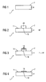
- FIG. 1 shows a component 1 which is to be coated with the gas phase coating method according to the invention.
- the component 1 has a substrate 4 with a surface 7 which is to be at least partially coated.
- the substrate 4 may be metallic or ceramic.
- the component 1 is in particular a component 1 of a turbomachine, ie a gas turbine of an aircraft or an installation for generating electric current 100 (FIG. 6), a steam turbine 300, 3003 (FIG. 7) or a compressor (for example 105, FIG ).
- the component 1 is a turbine blade 120, 130, 342, 354 (FIGS. 6, 7) or a combustor liner 155 (FIG. 6).
- the thermally highly stressed components of a turbomachine consist in particular of an iron-, cobalt- or nickel-based superalloy.
- the coating method according to the invention can be applied to newly produced components or components 1 to be reworked.
- FIG. 2 shows a method step of the method according to the invention.
- a multicomponent application agent 19 is applied in the form of a layer by means of a slurry 19 or a paste 19.
- the slip 19 can be applied at room temperature.
- the adhesion of the slip 19 on the component 1 can be effected in that the slip 19 contains a binder (for example, organic or inorganic).
- the slip 19 can also be mixed with a carrier liquid (water, alcohol, ..) with or without binder and brushed onto the component 1 or the component 1 is coated by immersion in a flowable mass of the slurry 19.
- a localized application is possible in any case.
- the slurry 19 contains an activator and at least one constituent of the coating material which is to form a layer 16 (FIG. 4) on the surface 7, 10.
- the activator can react with at least one constituent of the application agent to form a gas 13 (FIG. 3), which precipitates on the surface 7, 10.
- This process is described in US 6,217,668 which is intended to be part of this disclosure. This reaction takes place only from an elevated temperature.
- FIG. 3 shows a further method step of the method according to the invention.
- the temperature of the slurry 19 and, for example, that of the substrate 4 is increased so that a reaction of activator and a constituent of the slip 19, ie the application agent, takes place in the slurry 19.
- gaseous particles 13 form due to the reaction of the activator with a constituent of the slip 19, no material is melted, so that the process temperature and thus process costs can be kept correspondingly lower.
- halogens fluorine and / or chlorine or other gases
- the coating material (aluminum) and the activator (F) form a compound.
- the rate of formation of the gas 13 can be controlled by adding a carrier substance, for example a chemically inert material, for example a ceramic, in particular aluminum oxide or aluminum silicate, to the slurry 19, whereby the formation of the gas 13 is controlled and equalized. Only by reaching the reaction temperature which is below the melting temperature of the at least one constituent of the slip 19, the reaction and thus the gas phase coating is started. By falling below the reaction temperature, the process of gas phase formation and thereby also the coating process itself is stopped. This ensures the coating and control (layer thickness) of the process with high precision.
- a carrier substance for example a chemically inert material, for example a ceramic, in particular aluminum oxide or aluminum silicate
- the layer thickness determined from the proportion of the gas phase, which is evenly distributed due to their aggregate state. Moreover, the layer thickness depends on the residence time of the component 1 above the reaction temperature. After a certain time, the process can be stopped and possibly existing residues of the slip 19 are removed. What remains is then a desired coating 16 (FIG. 4).
- a diffusion treatment By a diffusion treatment, the connection of the layer 16 to the substrate 4 can be improved. In this case, material of the layer 16 diffuses into the substrate 4. An easy to apply and removable masking of the non-coated surfaces 11 is possible.
- the slurry 19 may contain as coating material a metal and / or a ceramic, such as aluminum, cobalt, chromium, nickel, silicon or zirconium oxide. Likewise, the slurry 19 may contain two coating materials to be deposited. This is, for example, aluminum and cobalt, or nickel and cobalt, cobalt and chromium or aluminum and chromium. Likewise, an alloy such as an MCrAlX alloy may be present in the slurry 19 and deposited.
- a metal and / or a ceramic such as aluminum, cobalt, chromium, nickel, silicon or zirconium oxide.
- the slurry 19 may contain two coating materials to be deposited. This is, for example, aluminum and cobalt, or nickel and cobalt, cobalt and chromium or aluminum and chromium.
- an alloy such as an MCrAlX alloy may be present in the slurry 19 and deposited.
- a metal or alloy may be present in the slurry 19 in the form of a metal complex.
- the component 1 must be introduced for the coating in an oven, in which the temperature can be increased.
- a vacuum does not necessarily exist.
- a reactive gas may be introduced into the furnace or into the vacuum to utilize a reactive vapor deposition process.
- React aluminum with oxygen as a reactive gas to gaseous alumina which then deposits as an aluminum oxide layer on the component 1 or the reactive gas reacts with the deposited metallic aluminum to aluminum oxide and also forms an aluminum oxide layer on the component.
- FIG. 5 shows an application example for the method according to the invention.
- the component is here a hollow component 1 ', as is the case for example with internally cooled turbine blades.
- a gas phase in particular in a CVD or PVD process according to the prior art, can penetrate only poorly into the interior of the component 1 '.
- the slip 19 is applied by pouring or simple application to the inner surface 25 of the component 1.
- By a heat treatment is carried out an inner coating.
- the possibly existing residues of the slip 19 can be removed by simple water jets, air jets and dry ice blasting.
- Even hard to reach areas of a hollow component 1 'as well as undercuts or hard to reach places are coated on a surface of the component.
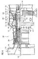
- FIG. 6 shows by way of example a gas turbine 100 in a longitudinal partial section.
- the gas turbine 100 has inside a rotatably mounted about a rotation axis 102 rotor 103, which is also referred to as a turbine runner.
- a suction housing 104 Along the rotor 103 follow one another a suction housing 104, a compressor 105, for example, a toroidal combustion chamber 110, in particular annular combustion chamber 106, with a plurality of coaxially arranged burners 107, a turbine 108 and the exhaust housing 109th
- the annular combustion chamber 106 communicates with an annular annular hot gas channel 111, for example.
- Each turbine stage 112 is formed, for example, from two blade rings. As seen in the direction of flow of a working medium 113, in the hot gas channel 111 of a row of guide vanes 115, a series 125 formed of rotor blades 120 follows.
- the guide vanes 130 are fastened to an inner housing 138 of a stator 143, whereas the moving blades 120 of a row 125 are attached to the rotor 103 by means of a turbine disk 133, for example.
- air 105 is sucked in and compressed by the compressor 105 through the intake housing 104.
- the compressed air provided at the turbine-side end of the compressor 105 is supplied to the burners 107 where it is mixed with a fuel.
- the mixture is then burned to form the working fluid 113 in the combustion chamber 110. From there, the working fluid 113 flows along the hot gas passage 111 past the vanes 130 and the blades 120.
- the working medium 113 expands in a pulse-transmitting manner, so that the rotor blades 120 drive the rotor 103 and drive the rotor coupled thereto.
- the components exposed to the hot working medium 113 are subject to thermal loads during operation of the gas turbine 100.
- the guide vanes 130 and rotor blades 120 of the first turbine stage 112, viewed in the direction of flow of the working medium 113, are subjected to the greatest thermal stress in addition to the heat shield bricks lining the annular combustion chamber 106. To withstand the prevailing temperatures, they can be cooled by means of a coolant.
- substrates of the components can have a directional structure, ie they are monocrystalline (SX structure) or have only longitudinal grains (DS structure).
- As the material for the components, in particular for the turbine blade 120, 130 and components of the combustion chamber 110 for example, iron-, nickel- or cobalt-based superalloys are used. Such superalloys are known, for example, from EP 1204776, EP 1306454, EP 1319729, WO 99/67435 or WO 00/44949; These documents are part of the disclosure of the present invention.
- the blades 120, 130 may be anti-corrosion coatings (MCrAlX; M is at least one element of the group iron (Fe), cobalt (Co), nickel (Ni), X is an active element and is yttrium (Y) and / or silicon and / or at least one element of the rare earths) and heat through a thermal barrier coating.
- M is at least one element of the group iron (Fe), cobalt (Co), nickel (Ni)
- X is an active element and is yttrium (Y) and / or silicon and / or at least one element of the rare earths
- the thermal barrier coating consists for example of ZrO 2 , Y 2 O 4 -ZrO 2 , ie it is not, partially or completely stabilized by yttrium oxide and / or calcium oxide and / or magnesium oxide.
- suitable coating processes such as electron beam evaporation (EB-PVD), stalk-shaped grains are produced in the thermal barrier coating.
- the turbine blades 120, 130 have an inner alkalization, which can be produced by means of the coating method according to the invention.
- the vane 130 has a guide vane foot (not shown here) facing the inner housing 138 of the turbine 108 and a vane head opposite the vane foot.
- the vane head faces the rotor 103 and fixed to a mounting ring 140 of the stator 143.
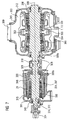
- FIG. 7 shows by way of example a steam turbine 300, 303 with a turbine shaft 309 extending along a rotation axis 306.
- the steam turbine has a high-pressure turbine section 300 and a medium-pressure turbine section 303, each having an inner housing 312 and an outer housing 315 enclosing this.
- the high-pressure turbine part 300 is designed, for example, in Topfbauart.
- the medium-pressure turbine section 303 is double-flow. It is also possible for the medium-pressure turbine section 303 to be single-flow.
- a bearing 318 is arranged between the high-pressure turbine section 300 and the medium-pressure turbine section 303, the turbine shaft 309 having a bearing region 321 in the bearing 318.
- the turbine shaft 309 is deposited on another bearing 324 adjacent to the high pressure turbine 300. In the area of this bearing 324, the high-pressure turbine section 300 has a shaft seal 345.
- the turbine shaft 309 is sealed from the outer housing 315 of the medium-pressure turbine section 303 by two further shaft seals 345. Between a high-pressure steam inflow region 348 and a steam outlet region 351, the turbine shaft 309 in the high-pressure turbine section 300 has the high-pressure impeller blade 354, 357. This high-pressure bladed runner 354, 357, together with the associated blades, not shown, represents a first blading region 360.
- the middle-pressure blast turbine 303 has a central steam inflow region 333.
- the turbine shaft 309 Associated with the steam inflow region 333, the turbine shaft 309 has a radially symmetrical shaft shield 363, a cover plate, on the one hand for dividing the steam flow into the two flows of the medium-pressure turbine section 303 and for preventing direct contact of the hot steam with the turbine shaft 309.
- the turbine shaft 309 has in the medium-pressure turbine section 303 a second blading area 366 with the medium-pressure blades 354, 342.
- the hot steam flowing through the second blading area 366 flows out of the medium-pressure turbine section 303 from a discharge connection 369 to a downstream low-pressure turbine, not shown.
- the turbine shaft 309 is composed of two sub-turbine shafts 309a and 309b, which are fixedly connected to one another in the region of the bearing 318.
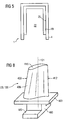
- FIG. 8 shows a perspective view of a blade 120, 130 which extends along a longitudinal axis 121.
- the blade 120 may be a blade 120 or stator 130 of a turbomachine.
- the turbomachine may be a gas turbine of an aircraft or a power plant for Electricity generation, a steam turbine or a compressor.
- the blade 120, 130 has along the longitudinal axis 121 consecutively a fastening region 400, a blade platform 403 adjoining thereto and an airfoil 406.
- As a guide blade 130, the blade at its blade tip 415 may have another platform (not shown).
- a blade root 183 is formed, which serves for attachment of the blades 120, 130 to a shaft or a disc (not shown).
- the blade root 183 is designed, for example, as a hammer head.
- the blade 120, 130 has a leading edge 409 and a trailing edge 412 for a medium flowing past the airfoil 406.
- blade 120, 130 for example, solid metallic materials are used in all regions 400, 403, 406 of the blade 120, 130.
- the blade 120, 130 may in this case be produced by a casting process, also by directional solidification, by a forging process, by a milling process.
- directionally solidified microstructures which means both single crystals that have no grain boundaries or at most small angle grain boundaries, and stem crystal structures that have probably longitudinal grain boundaries but no transverse grain boundaries. These second-mentioned crystalline structures are also known as directionally solidified structures.
- Refurbishment means that components 120, 130 may need to be deprotected after use (e.g., by sandblasting). This is followed by removal of the corrosion and / or oxidation layers or products. Optionally, even cracks in the component 120, 130 are repaired. This is followed by a recoating (for example with the method according to the invention) of the component 120, 130 and a renewed use of the component 120, 130.
- the blade 120, 130 may be hollow or solid. When the blade 120, 130 is to be cooled, it is hollow and may still have film cooling holes (not shown).
- the blade 120, 130 for example, corresponding mostly metallic coatings (eg. With the inventive method) and as protection against heat usually still a ceramic coating.
Landscapes
- Chemical & Material Sciences (AREA)
- Chemical Kinetics & Catalysis (AREA)
- Engineering & Computer Science (AREA)
- Materials Engineering (AREA)
- Mechanical Engineering (AREA)
- Metallurgy (AREA)
- Organic Chemistry (AREA)
- Turbine Rotor Nozzle Sealing (AREA)
- Other Surface Treatments For Metallic Materials (AREA)
Claims (8)
- Procédé de dépôt en phase gazeuse,
notamment pour le dépôt local en phase gazeuse,
d'un composant (1) à l'aide d'un agent (19) de dépôt à plusieurs constituants qui contient,
un activateur et
une matière de revêtement,
qui a deux constituants métalliques,
qui doivent être déposés,
l'activateur formant par échauffement, par réaction sur au moins un constituant de l'agent (19) de dépôt, une phase (13) gazeuse,
de sorte que la au moins une matière de revêtement recouvre le composant (1),
l'activateur et le au moins une matière de revêtement représentant une liaison MeHa,
Me étant un métal et Ha étant un halogène,
notamment le fluor,
qui sert d'activateur et,
l'agent (19) de dépôt contenant
deux matières de revêtement,
qui sont déposées,
qui sont choisies dans le groupe
de l'aluminium et du cobalt,
du nickel et du cobalt,
du cobalt et du chrome ou
de l'aluminium et du chrome. - Procédé suivant la revendication 1, dans lequel l'activateur est un halogène ou un halogénure.
- Procédé suivant la revendication 1 ou 2, dans lequel on effectue le procédé en-dessous d'un point de fusion de la au moins une matière de revêtement.
- Procédé suivant la revendication 1, dans lequel on effectue le procédé pour revêtir intérieurement un composant (1') creux.
- Procédé suivant la revendication 1,
dans lequel on dépose l'agent (19) de dépôt sur l'élément (1), et
on échauffe l'agent (19) de dépôt dans un stade supplémentaire de procédé,
de manière à former une phase (13) gazeuse
qui donne le revêtement en phase gazeuse ayant la matière de revêtement souhaitée,
et dans lequel, dans le dernier stade du procédé, on abaisse la température pour arrêter la réaction et on élimine, dans l'un des stades finaux de procédés, le cas échéant des restes de l'agent (19) de dépôt. - Procédé suivant l'une ou plusieurs des revendications précédentes
dans lequel on effectue le procédé sur un composant (1) nouvellement produit. - Procédé suivant l'une ou plusieurs des revendications précédentes
dans lequel on effectue le procédé sur un composant (1) à retraiter. - Procédé suivant la revendication 7, dans lequel le composant (1, 1') est un composant d'une turbine à vapeur (300, 303) ou d'une turbine à gaz (100), notamment une aube (120, 130, 342, 354) de turbine ou un revêtement (155) de chambre de combustion.
Priority Applications (2)
| Application Number | Priority Date | Filing Date | Title |
|---|---|---|---|
| DE50306397T DE50306397D1 (de) | 2003-11-27 | 2003-11-27 | Gasphasenbeschichtungsverfahren |
| EP03027389A EP1536033B1 (fr) | 2003-11-27 | 2003-11-27 | Dépôt en phase vapeur |
Applications Claiming Priority (1)
| Application Number | Priority Date | Filing Date | Title |
|---|---|---|---|
| EP03027389A EP1536033B1 (fr) | 2003-11-27 | 2003-11-27 | Dépôt en phase vapeur |
Publications (2)
| Publication Number | Publication Date |
|---|---|
| EP1536033A1 EP1536033A1 (fr) | 2005-06-01 |
| EP1536033B1 true EP1536033B1 (fr) | 2007-01-24 |
Family
ID=34442901
Family Applications (1)
| Application Number | Title | Priority Date | Filing Date |
|---|---|---|---|
| EP03027389A Expired - Lifetime EP1536033B1 (fr) | 2003-11-27 | 2003-11-27 | Dépôt en phase vapeur |
Country Status (2)
| Country | Link |
|---|---|
| EP (1) | EP1536033B1 (fr) |
| DE (1) | DE50306397D1 (fr) |
Family Cites Families (4)
| Publication number | Priority date | Publication date | Assignee | Title |
|---|---|---|---|---|
| US5100486A (en) * | 1989-04-14 | 1992-03-31 | The United States Of America As Represented By The United States Department Of Energy | Method of coating metal surfaces to form protective metal coating thereon |
| US5366765A (en) * | 1993-05-17 | 1994-11-22 | United Technologies Corporation | Aqueous slurry coating system for aluminide coatings |
| US6110262A (en) * | 1998-08-31 | 2000-08-29 | Sermatech International, Inc. | Slurry compositions for diffusion coatings |
| US6497920B1 (en) * | 2000-09-06 | 2002-12-24 | General Electric Company | Process for applying an aluminum-containing coating using an inorganic slurry mix |
-
2003
- 2003-11-27 DE DE50306397T patent/DE50306397D1/de not_active Expired - Lifetime
- 2003-11-27 EP EP03027389A patent/EP1536033B1/fr not_active Expired - Lifetime
Also Published As
| Publication number | Publication date |
|---|---|
| DE50306397D1 (de) | 2007-03-15 |
| EP1536033A1 (fr) | 2005-06-01 |
Similar Documents
| Publication | Publication Date | Title |
|---|---|---|
| EP2458025B1 (fr) | Alliage, couche de protection et composant | |
| EP2612949B1 (fr) | Alliage, couche de protection et composant | |
| EP1708829B1 (fr) | Procede pour eliminer une couche | |
| EP1666625A1 (fr) | Procédé de revêtement d'un composant a l'interieur d'un aparat | |
| EP1693473B1 (fr) | Alliage-MCrAlX, couche protectrice en cet alliage et son procédé de fabrication | |
| EP2710167B1 (fr) | Alliage, couche de protection et composant | |
| EP1722901B1 (fr) | Procede de nettoyage au plasma d'un composant | |
| EP2474413A1 (fr) | Alliage, couche de protection et composant | |
| EP1798299B1 (fr) | Alliage, couche de protection et élément de construction | |
| EP1536033B1 (fr) | Dépôt en phase vapeur | |
| EP2611949B1 (fr) | Alliage a base nickel, couche de protection et élément de construction | |
| EP1586675B1 (fr) | Procédé de revêtement de l'intérieur d'un corps creux | |
| EP1772531A1 (fr) | Procédé et appareil de revêtement intérieur. | |
| EP1681374B1 (fr) | Système de revêtement comprenant une couche barrière et procédé de fabrication | |
| WO2007085512A1 (fr) | Procede de fabrication d'un composant dote de trous | |
| EP1676938A1 (fr) | Methode de fabrication d'un component d'une turbine et le component d'une turbine | |
| EP1772529A1 (fr) | Composition chimique sèche, utilisation de celle-ci composition pour fabriquer un revêtement multicouche et méthode pour fabriquer ce revêtement | |
| DE202005020695U1 (de) | Schichtsystem | |
| EP1806419B1 (fr) | Alliage, couche protectrice pour proteger un élément structurel contre la corrosion et l'oxydation aux temperatures hautes, et élément structurel | |
| EP1808236A1 (fr) | Procédé pour masquer des trous de refroidissement, en particulier d'aubes de turbine | |
| EP1783243A1 (fr) | Composition sèche, son utilisation, système de couches et procédé de revêtement | |
| WO2007042396A1 (fr) | Dispositif et procédé d'enduction intérieure, cornue | |
| EP2345748A1 (fr) | Alliage, couche de protection et composant | |
| EP1731628A1 (fr) | Procédé pour augmenter l'épaisseur de la paroi d'une pièce à base d'un alliage résistant aux températures élevées | |
| WO2006053838A2 (fr) | Procede de coulee et piece coulee |
Legal Events
| Date | Code | Title | Description |
|---|---|---|---|
| PUAI | Public reference made under article 153(3) epc to a published international application that has entered the european phase |
Free format text: ORIGINAL CODE: 0009012 |
|
| AK | Designated contracting states |
Kind code of ref document: A1 Designated state(s): AT BE BG CH CY CZ DE DK EE ES FI FR GB GR HU IE IT LI LU MC NL PT RO SE SI SK TR |
|
| AX | Request for extension of the european patent |
Extension state: AL LT LV MK |
|
| 17P | Request for examination filed |
Effective date: 20050620 |
|
| GRAP | Despatch of communication of intention to grant a patent |
Free format text: ORIGINAL CODE: EPIDOSNIGR1 |
|
| AKX | Designation fees paid |
Designated state(s): CH DE GB IT LI |
|
| GRAS | Grant fee paid |
Free format text: ORIGINAL CODE: EPIDOSNIGR3 |
|
| GRAA | (expected) grant |
Free format text: ORIGINAL CODE: 0009210 |
|
| AK | Designated contracting states |
Kind code of ref document: B1 Designated state(s): CH DE GB IT LI |
|
| REG | Reference to a national code |
Ref country code: GB Ref legal event code: FG4D Free format text: NOT ENGLISH |
|
| REG | Reference to a national code |
Ref country code: CH Ref legal event code: EP Ref country code: CH Ref legal event code: NV Representative=s name: SIEMENS SCHWEIZ AG |
|
| REF | Corresponds to: |
Ref document number: 50306397 Country of ref document: DE Date of ref document: 20070315 Kind code of ref document: P |
|
| GBT | Gb: translation of ep patent filed (gb section 77(6)(a)/1977) |
Effective date: 20070410 |
|
| PLBE | No opposition filed within time limit |
Free format text: ORIGINAL CODE: 0009261 |
|
| STAA | Information on the status of an ep patent application or granted ep patent |
Free format text: STATUS: NO OPPOSITION FILED WITHIN TIME LIMIT |
|
| 26N | No opposition filed |
Effective date: 20071025 |
|
| REG | Reference to a national code |
Ref country code: CH Ref legal event code: PCAR Free format text: SIEMENS SCHWEIZ AG;INTELLECTUAL PROPERTY FREILAGERSTRASSE 40;8047 ZUERICH (CH) |
|
| PGFP | Annual fee paid to national office [announced via postgrant information from national office to epo] |
Ref country code: IT Payment date: 20101125 Year of fee payment: 8 Ref country code: GB Payment date: 20101111 Year of fee payment: 8 |
|
| PGFP | Annual fee paid to national office [announced via postgrant information from national office to epo] |
Ref country code: CH Payment date: 20120206 Year of fee payment: 9 |
|
| PGFP | Annual fee paid to national office [announced via postgrant information from national office to epo] |
Ref country code: DE Payment date: 20120120 Year of fee payment: 9 |
|
| REG | Reference to a national code |
Ref country code: CH Ref legal event code: PL |
|
| GBPC | Gb: european patent ceased through non-payment of renewal fee |
Effective date: 20121127 |
|
| PG25 | Lapsed in a contracting state [announced via postgrant information from national office to epo] |
Ref country code: CH Free format text: LAPSE BECAUSE OF NON-PAYMENT OF DUE FEES Effective date: 20121130 Ref country code: LI Free format text: LAPSE BECAUSE OF NON-PAYMENT OF DUE FEES Effective date: 20121130 |
|
| PG25 | Lapsed in a contracting state [announced via postgrant information from national office to epo] |
Ref country code: IT Free format text: LAPSE BECAUSE OF NON-PAYMENT OF DUE FEES Effective date: 20121127 |
|
| REG | Reference to a national code |
Ref country code: DE Ref legal event code: R119 Ref document number: 50306397 Country of ref document: DE Effective date: 20130601 |
|
| PG25 | Lapsed in a contracting state [announced via postgrant information from national office to epo] |
Ref country code: DE Free format text: LAPSE BECAUSE OF NON-PAYMENT OF DUE FEES Effective date: 20130601 |
|
| PG25 | Lapsed in a contracting state [announced via postgrant information from national office to epo] |
Ref country code: GB Free format text: LAPSE BECAUSE OF NON-PAYMENT OF DUE FEES Effective date: 20121127 |