EP1536079A2 - Conduit de lumière - Google Patents
Conduit de lumière Download PDFInfo
- Publication number
- EP1536079A2 EP1536079A2 EP04257222A EP04257222A EP1536079A2 EP 1536079 A2 EP1536079 A2 EP 1536079A2 EP 04257222 A EP04257222 A EP 04257222A EP 04257222 A EP04257222 A EP 04257222A EP 1536079 A2 EP1536079 A2 EP 1536079A2
- Authority
- EP
- European Patent Office
- Prior art keywords
- duct
- end portion
- light directing
- hinge
- light
- Prior art date
- Legal status (The legal status is an assumption and is not a legal conclusion. Google has not performed a legal analysis and makes no representation as to the accuracy of the status listed.)
- Withdrawn
Links
- 238000005452 bending Methods 0.000 description 1
- 230000003313 weakening effect Effects 0.000 description 1
Images


Classifications
-
- E—FIXED CONSTRUCTIONS
- E04—BUILDING
- E04D—ROOF COVERINGS; SKY-LIGHTS; GUTTERS; ROOF-WORKING TOOLS
- E04D13/00—Special arrangements or devices in connection with roof coverings; Protection against birds; Roof drainage ; Sky-lights
- E04D13/03—Sky-lights; Domes; Ventilating sky-lights
-
- E—FIXED CONSTRUCTIONS
- E04—BUILDING
- E04F—FINISHING WORK ON BUILDINGS, e.g. STAIRS, FLOORS
- E04F17/00—Vertical ducts; Channels, e.g. for drainage
- E04F17/06—Light shafts, e.g. for cellars
-
- F—MECHANICAL ENGINEERING; LIGHTING; HEATING; WEAPONS; BLASTING
- F16—ENGINEERING ELEMENTS AND UNITS; GENERAL MEASURES FOR PRODUCING AND MAINTAINING EFFECTIVE FUNCTIONING OF MACHINES OR INSTALLATIONS; THERMAL INSULATION IN GENERAL
- F16L—PIPES; JOINTS OR FITTINGS FOR PIPES; SUPPORTS FOR PIPES, CABLES OR PROTECTIVE TUBING; MEANS FOR THERMAL INSULATION IN GENERAL
- F16L27/00—Adjustable joints; Joints allowing movement
- F16L27/02—Universal joints, i.e. with mechanical connection allowing angular movement or adjustment of the axes of the parts in any direction
-
- E—FIXED CONSTRUCTIONS
- E04—BUILDING
- E04D—ROOF COVERINGS; SKY-LIGHTS; GUTTERS; ROOF-WORKING TOOLS
- E04D13/00—Special arrangements or devices in connection with roof coverings; Protection against birds; Roof drainage ; Sky-lights
- E04D13/03—Sky-lights; Domes; Ventilating sky-lights
- E04D2013/034—Daylight conveying tubular skylights
- E04D2013/0345—Daylight conveying tubular skylights with skylight shafts extending from roof to ceiling
-
- F—MECHANICAL ENGINEERING; LIGHTING; HEATING; WEAPONS; BLASTING
- F21—LIGHTING
- F21S—NON-PORTABLE LIGHTING DEVICES; SYSTEMS THEREOF; VEHICLE LIGHTING DEVICES SPECIALLY ADAPTED FOR VEHICLE EXTERIORS
- F21S11/00—Non-electric lighting devices or systems using daylight
Definitions
- This invention relates to light directing ducts, for example, as used to direct light from a skylight into a room of a building.
- sun-pipes Light directing ducts, or "sun-pipes" are widely used to bring natural light into a living or working space.
- the sun-pipe is a tube running from the roof of the building to the ceiling of the living or working space, the inside of which is made from a light reflective material.
- Commonly known sun-pipes are straight tubes, running from roof to ceiling, so that the light inlet must be positioned directly above the light outlet. This necessitates the tube being cut down to fit against the slope of a roof, and means that the location one can choose to have a natural light opening in their living or work space is limited by where it is possible to make the light inlet in the roof.
- US Patent Application No. 10/619753 discloses apparatus for illuminating the interior of a building.
- a light directing duct comprising a first end portion and a second end portion, the first end portion and second end portion being interconnected by a hinge.
- the hinge is provided across only one side of the duct.
- the first end portion comprises a tongue which extends into the second end portion.
- the tongue extends into the second end portion on a side of the duct opposite to the hinge.
- the tongue is made from a flexible material, so that when the first end portion is rotated relative to the second end portion, the tongue is able to bend.
- the two sides of one of the end portions adjacent to the side of the duct with the hinge comprise projections having curved guide surfaces along which the other end portion tracks.
- the internal surfaces of the duct are adapted to reflect light.
- the duct has a rectangular cross section.
- the duct has a square cross section.
- the duct is adapted for use between a skylight and a room of a building.
- the hinge comprises a living hinge.
- the living hinge may be formed by scoring or otherwise weakening a sheet of material along a desired hinge line.
- the living hinge could be made from the same material as a wall of the duct.
- the living hinge is formed from flexible material attached to a wall of the duct.
- Figures 1 to 5 show a light directing duct adapted for use between a sky light and a room of a building to bring natural light into the room.
- the light directing duct comprises a first end portion 2 connected to a second end portion 4 by a hinge 30.
- the internal surfaces of the duct are made from a light reflecting material so that light is reflected down the duct from the skylight to the room below.
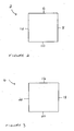
- Figure 2 shows a cross section of the first end portion 2, comprising four side walls 6, 8, 10 and 12.
- Figure 3 shows a cross section of the second end portion comprising four side walls 16, 18, 20 and 22.
- the hinge 30 connects walls 10 and 20.
- a tongue 32 is fixed inside wall 16 of the second end portion and projects into the first end portion adjacent to wall 6.
- Fixed inside wall 18 of the second end portion is a projection comprising a first guide plate 34 which projects into the first end portion adjacent to wall 8
- fixed inside wall 22 of the second portion is another projection comprising a second guide plate 36 which projects into the first end portion adjacent to wall 12.
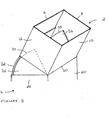
- the first and second guide plates 34, 36 have the shape of a segment of a circle, centred on hinge 30 such that the edges 35, 37 of the first and second guide plates adjacent to the tongue 32 are curved.
- the wall 6 of the first end portion of the duct rides up the tongue 32 and the curved edges 35, 37 of the first and second guide plates 34, 36, so that the duct becomes bent.
- the degree of the bend can be adjusted to match the pitch of the roof to which the duct is to be fitted.
- the second end portion 4 can be fitted first, and then the first end portion can be rotated about the hinge until the first end portion 2 abuts the roof evenly.
- the wall 6, opposites the hinge rides up the tongue 32, which is fixed to the wall 16 of the second end portion 4, and slides against the inside of wall 6.
- the tongue 32 is preferably made of a flexible material. The tongue is thus able to bend to seal off the gap between walls 6 and 16.
- the first and second guide plates serve to seal off the gap between walls 8 and 18 and 12 and 22 respectively, as the first end portion 2 pivots relative to the second end portion 4 about the hinge 30.
- Figure 5 shows a 3-dimensional representation of the light directing duct in the bent position. Clearly shown are the tongue 32 bending with the first end portion 2 and the guide plates 34 and 36 guiding the tongue.
- the hinge 30 may comprise a living hinge. This may be formed from the same material as the sides of the duct, or may be formed from a flexible material such as duct tape attached to the side of the duct.
Landscapes
- Engineering & Computer Science (AREA)
- Architecture (AREA)
- Civil Engineering (AREA)
- Structural Engineering (AREA)
- General Engineering & Computer Science (AREA)
- Mechanical Engineering (AREA)
- Non-Portable Lighting Devices Or Systems Thereof (AREA)
- Duct Arrangements (AREA)
Applications Claiming Priority (2)
| Application Number | Priority Date | Filing Date | Title |
|---|---|---|---|
| GB0327712A GB2408522B (en) | 2003-11-28 | 2003-11-28 | Light directing duct |
| GB0327712 | 2003-11-28 |
Publications (2)
| Publication Number | Publication Date |
|---|---|
| EP1536079A2 true EP1536079A2 (fr) | 2005-06-01 |
| EP1536079A3 EP1536079A3 (fr) | 2007-09-19 |
Family
ID=29798014
Family Applications (1)
| Application Number | Title | Priority Date | Filing Date |
|---|---|---|---|
| EP04257222A Withdrawn EP1536079A3 (fr) | 2003-11-28 | 2004-11-22 | Conduit de lumière |
Country Status (3)
| Country | Link |
|---|---|
| US (1) | US20050115172A1 (fr) |
| EP (1) | EP1536079A3 (fr) |
| GB (1) | GB2408522B (fr) |
Citations (1)
| Publication number | Priority date | Publication date | Assignee | Title |
|---|---|---|---|---|
| US689894A (en) | 1901-05-23 | 1901-12-31 | Emmett D Page | Elbow for conduits for electric wires. |
Family Cites Families (17)
| Publication number | Priority date | Publication date | Assignee | Title |
|---|---|---|---|---|
| DE121157C (fr) * | ||||
| US3520245A (en) * | 1969-08-19 | 1970-07-14 | Jenn Air Corp | Relief and intake air vent for building roofs |
| US3742659A (en) * | 1971-06-14 | 1973-07-03 | H Drew | Apparatus for mounting equipment on a roof |
| US3934383A (en) * | 1973-07-09 | 1976-01-27 | Perry Loren L | Roof vent |
| DE2436122A1 (de) * | 1974-07-26 | 1976-02-12 | Vladimir Smetana | Beleuchtungstubus mit innenspiegel |
| US4339900A (en) * | 1980-09-29 | 1982-07-20 | Freeman William T | Sky-light structure having a flexible-tube shaft |
| US4399900A (en) * | 1980-12-22 | 1983-08-23 | Allis-Chalmers Corporation | Centrifugal hydraulic head relief valve |
| US4526091A (en) * | 1984-08-02 | 1985-07-02 | Reynalda Clack | Adjustable roof jack |
| DE8507135U1 (de) * | 1985-03-12 | 1985-05-15 | Fischbach GmbH & Co KG Verwaltungsgesellschaft, 5908 Neunkirchen | Sockel zur Montage eines Lüftungsgerätes auf einem Dach |
| FR2621940A1 (fr) * | 1987-10-19 | 1989-04-21 | Siplast Sa | Conduit souple utilisable pour relier deux ouvertures et notamment pour canaliser un flux lumineux d'une ouverture captant la lumiere vers une ouverture diffusant la lumiere et systeme d'eclairement naturel d'une piece d'un batiment utilisant ledit conduit souple |
| US5409266A (en) * | 1994-03-15 | 1995-04-25 | Skyline Metal Products, Inc. | Adjustable roof jack |
| US5502935A (en) * | 1994-07-18 | 1996-04-02 | Demmer; Albert J. | Roof to ceiling skylight apparatus |
| US5546712A (en) * | 1994-11-03 | 1996-08-20 | Bixby; Joseph A. | System and method of constructing a skylight |
| PL111432U1 (en) * | 2000-09-20 | 2002-03-25 | Studio Dom Sp Z Oo | Skylight |
| US7146768B2 (en) * | 2001-03-30 | 2006-12-12 | Solatube International, Inc. | Skylight tube with reflective film and surface irregularities |
| US6585195B2 (en) * | 2001-04-25 | 2003-07-01 | Adc Telecommunications, Inc. | Cable management system including variable segments |
| US20030066254A1 (en) * | 2001-10-04 | 2003-04-10 | Deblock David A. | Tubular skylight with improved one-piece curb and tube |
-
2003
- 2003-11-28 GB GB0327712A patent/GB2408522B/en not_active Expired - Lifetime
-
2004
- 2004-11-22 EP EP04257222A patent/EP1536079A3/fr not_active Withdrawn
- 2004-11-27 US US10/998,236 patent/US20050115172A1/en not_active Abandoned
Patent Citations (1)
| Publication number | Priority date | Publication date | Assignee | Title |
|---|---|---|---|---|
| US689894A (en) | 1901-05-23 | 1901-12-31 | Emmett D Page | Elbow for conduits for electric wires. |
Also Published As
| Publication number | Publication date |
|---|---|
| GB0327712D0 (en) | 2003-12-31 |
| US20050115172A1 (en) | 2005-06-02 |
| GB2408522A (en) | 2005-06-01 |
| EP1536079A3 (fr) | 2007-09-19 |
| GB2408522B (en) | 2008-07-23 |
Similar Documents
| Publication | Publication Date | Title |
|---|---|---|
| CN102803627B (zh) | 具有多段的天窗准直管 | |
| EP1040236B1 (fr) | Systeme de grille pour la suspension de panneaux secs | |
| US4690192A (en) | Replaceable awning | |
| WO1995035515A3 (fr) | Composite utilise pour la regulation lumineuse ou pour assurer la confidentialite | |
| US12140282B2 (en) | Recessed curved channel light system | |
| WO2000043815A1 (fr) | Conducteur de lumiere utilisant des feuilles de plastique | |
| US5010709A (en) | Bendable channel construction element | |
| US5885153A (en) | Eave ventilation system | |
| US20090011696A1 (en) | Ventilation device and frame system | |
| US20050115172A1 (en) | Light directing duct | |
| GB2400885A (en) | Lighting apparatus | |
| US4008654A (en) | Adjustable air blade for air handling luminaires | |
| JP3190926B1 (ja) | 天井埋込型空気調和装置用の天井パネル構造体 | |
| JP2001216821A (ja) | 導光ダクト用光導入装置 | |
| JPS6238254Y2 (fr) | ||
| US12241602B1 (en) | Articulated lighting channel | |
| US2348148A (en) | Ventilator | |
| ATE136637T1 (de) | Dachflächenentlüfter | |
| JP3635533B2 (ja) | 配管カバー | |
| JP2021057206A (ja) | 導光ダクト | |
| JP3130011U (ja) | 光ダクト装置 | |
| JPH08109718A (ja) | 竪樋接続具 | |
| GB2376698A (en) | Gutter corner piece | |
| JPH0345176B2 (fr) | ||
| EP0859189A1 (fr) | Dispositif d'éclairage avec conduit de ventilation |
Legal Events
| Date | Code | Title | Description |
|---|---|---|---|
| PUAI | Public reference made under article 153(3) epc to a published international application that has entered the european phase |
Free format text: ORIGINAL CODE: 0009012 |
|
| AK | Designated contracting states |
Kind code of ref document: A2 Designated state(s): AT BE BG CH CY CZ DE DK EE ES FI FR GB GR HU IE IS IT LI LU MC NL PL PT RO SE SI SK TR |
|
| AX | Request for extension of the european patent |
Extension state: AL HR LT LV MK YU |
|
| PUAL | Search report despatched |
Free format text: ORIGINAL CODE: 0009013 |
|
| AK | Designated contracting states |
Kind code of ref document: A3 Designated state(s): AT BE BG CH CY CZ DE DK EE ES FI FR GB GR HU IE IS IT LI LU MC NL PL PT RO SE SI SK TR |
|
| AX | Request for extension of the european patent |
Extension state: AL HR LT LV MK YU |
|
| 17P | Request for examination filed |
Effective date: 20080318 |
|
| AKX | Designation fees paid |
Designated state(s): AT BE BG CH CY CZ DE DK EE ES FI FR GB GR HU IE IS IT LI LU MC NL PL PT RO SE SI SK TR |
|
| RIN1 | Information on inventor provided before grant (corrected) |
Inventor name: SKUSE, TONYC/O LITEFORME LIMITED |
|
| 17Q | First examination report despatched |
Effective date: 20080902 |
|
| STAA | Information on the status of an ep patent application or granted ep patent |
Free format text: STATUS: THE APPLICATION IS DEEMED TO BE WITHDRAWN |
|
| 18D | Application deemed to be withdrawn |
Effective date: 20100601 |