EP1536113A2 - Silencieux d'échappement avec catalyseur intégré - Google Patents
Silencieux d'échappement avec catalyseur intégré Download PDFInfo
- Publication number
- EP1536113A2 EP1536113A2 EP04105619A EP04105619A EP1536113A2 EP 1536113 A2 EP1536113 A2 EP 1536113A2 EP 04105619 A EP04105619 A EP 04105619A EP 04105619 A EP04105619 A EP 04105619A EP 1536113 A2 EP1536113 A2 EP 1536113A2
- Authority
- EP
- European Patent Office
- Prior art keywords
- chamber
- inlet
- housing
- outlet
- catalyst
- Prior art date
- Legal status (The legal status is an assumption and is not a legal conclusion. Google has not performed a legal analysis and makes no representation as to the accuracy of the status listed.)
- Granted
Links
Images


Classifications
-
- F—MECHANICAL ENGINEERING; LIGHTING; HEATING; WEAPONS; BLASTING
- F01—MACHINES OR ENGINES IN GENERAL; ENGINE PLANTS IN GENERAL; STEAM ENGINES
- F01N—GAS-FLOW SILENCERS OR EXHAUST APPARATUS FOR MACHINES OR ENGINES IN GENERAL; GAS-FLOW SILENCERS OR EXHAUST APPARATUS FOR INTERNAL-COMBUSTION ENGINES
- F01N1/00—Silencing apparatus characterised by method of silencing
- F01N1/02—Silencing apparatus characterised by method of silencing by using resonance
- F01N1/04—Silencing apparatus characterised by method of silencing by using resonance having sound-absorbing materials in resonance chambers
-
- F—MECHANICAL ENGINEERING; LIGHTING; HEATING; WEAPONS; BLASTING
- F01—MACHINES OR ENGINES IN GENERAL; ENGINE PLANTS IN GENERAL; STEAM ENGINES
- F01N—GAS-FLOW SILENCERS OR EXHAUST APPARATUS FOR MACHINES OR ENGINES IN GENERAL; GAS-FLOW SILENCERS OR EXHAUST APPARATUS FOR INTERNAL-COMBUSTION ENGINES
- F01N3/00—Exhaust or silencing apparatus having means for purifying, rendering innocuous, or otherwise treating exhaust
- F01N3/08—Exhaust or silencing apparatus having means for purifying, rendering innocuous, or otherwise treating exhaust for rendering innocuous
- F01N3/10—Exhaust or silencing apparatus having means for purifying, rendering innocuous, or otherwise treating exhaust for rendering innocuous by thermal or catalytic conversion of noxious components of exhaust
- F01N3/24—Exhaust or silencing apparatus having means for purifying, rendering innocuous, or otherwise treating exhaust for rendering innocuous by thermal or catalytic conversion of noxious components of exhaust characterised by constructional aspects of converting apparatus
- F01N3/28—Construction of catalytic reactors
- F01N3/2882—Catalytic reactors combined or associated with other devices, e.g. exhaust silencers or other exhaust purification devices
- F01N3/2885—Catalytic reactors combined or associated with other devices, e.g. exhaust silencers or other exhaust purification devices with exhaust silencers in a single housing
-
- F—MECHANICAL ENGINEERING; LIGHTING; HEATING; WEAPONS; BLASTING
- F01—MACHINES OR ENGINES IN GENERAL; ENGINE PLANTS IN GENERAL; STEAM ENGINES
- F01N—GAS-FLOW SILENCERS OR EXHAUST APPARATUS FOR MACHINES OR ENGINES IN GENERAL; GAS-FLOW SILENCERS OR EXHAUST APPARATUS FOR INTERNAL-COMBUSTION ENGINES
- F01N3/00—Exhaust or silencing apparatus having means for purifying, rendering innocuous, or otherwise treating exhaust
- F01N3/08—Exhaust or silencing apparatus having means for purifying, rendering innocuous, or otherwise treating exhaust for rendering innocuous
- F01N3/10—Exhaust or silencing apparatus having means for purifying, rendering innocuous, or otherwise treating exhaust for rendering innocuous by thermal or catalytic conversion of noxious components of exhaust
- F01N3/24—Exhaust or silencing apparatus having means for purifying, rendering innocuous, or otherwise treating exhaust for rendering innocuous by thermal or catalytic conversion of noxious components of exhaust characterised by constructional aspects of converting apparatus
- F01N3/28—Construction of catalytic reactors
- F01N3/2892—Exhaust flow directors or the like, e.g. upstream of catalytic device
-
- F—MECHANICAL ENGINEERING; LIGHTING; HEATING; WEAPONS; BLASTING
- F01—MACHINES OR ENGINES IN GENERAL; ENGINE PLANTS IN GENERAL; STEAM ENGINES
- F01N—GAS-FLOW SILENCERS OR EXHAUST APPARATUS FOR MACHINES OR ENGINES IN GENERAL; GAS-FLOW SILENCERS OR EXHAUST APPARATUS FOR INTERNAL-COMBUSTION ENGINES
- F01N2450/00—Methods or apparatus for fitting, inserting or repairing different elements
- F01N2450/22—Methods or apparatus for fitting, inserting or repairing different elements by welding or brazing
-
- F—MECHANICAL ENGINEERING; LIGHTING; HEATING; WEAPONS; BLASTING
- F01—MACHINES OR ENGINES IN GENERAL; ENGINE PLANTS IN GENERAL; STEAM ENGINES
- F01N—GAS-FLOW SILENCERS OR EXHAUST APPARATUS FOR MACHINES OR ENGINES IN GENERAL; GAS-FLOW SILENCERS OR EXHAUST APPARATUS FOR INTERNAL-COMBUSTION ENGINES
- F01N2470/00—Structure or shape of exhaust gas passages, pipes or tubes
- F01N2470/02—Tubes being perforated
-
- F—MECHANICAL ENGINEERING; LIGHTING; HEATING; WEAPONS; BLASTING
- F01—MACHINES OR ENGINES IN GENERAL; ENGINE PLANTS IN GENERAL; STEAM ENGINES
- F01N—GAS-FLOW SILENCERS OR EXHAUST APPARATUS FOR MACHINES OR ENGINES IN GENERAL; GAS-FLOW SILENCERS OR EXHAUST APPARATUS FOR INTERNAL-COMBUSTION ENGINES
- F01N2470/00—Structure or shape of exhaust gas passages, pipes or tubes
- F01N2470/14—Plurality of outlet tubes, e.g. in parallel or with different length
-
- F—MECHANICAL ENGINEERING; LIGHTING; HEATING; WEAPONS; BLASTING
- F01—MACHINES OR ENGINES IN GENERAL; ENGINE PLANTS IN GENERAL; STEAM ENGINES
- F01N—GAS-FLOW SILENCERS OR EXHAUST APPARATUS FOR MACHINES OR ENGINES IN GENERAL; GAS-FLOW SILENCERS OR EXHAUST APPARATUS FOR INTERNAL-COMBUSTION ENGINES
- F01N2490/00—Structure, disposition or shape of gas-chambers
- F01N2490/02—Two or more expansion chambers in series connected by means of tubes
- F01N2490/04—Two or more expansion chambers in series connected by means of tubes the gases flowing longitudinally from inlet to outlet only in one direction
-
- F—MECHANICAL ENGINEERING; LIGHTING; HEATING; WEAPONS; BLASTING
- F01—MACHINES OR ENGINES IN GENERAL; ENGINE PLANTS IN GENERAL; STEAM ENGINES
- F01N—GAS-FLOW SILENCERS OR EXHAUST APPARATUS FOR MACHINES OR ENGINES IN GENERAL; GAS-FLOW SILENCERS OR EXHAUST APPARATUS FOR INTERNAL-COMBUSTION ENGINES
- F01N2490/00—Structure, disposition or shape of gas-chambers
- F01N2490/14—Dead or resonance chambers connected to gas flow tube by relatively short side-tubes
-
- F—MECHANICAL ENGINEERING; LIGHTING; HEATING; WEAPONS; BLASTING
- F01—MACHINES OR ENGINES IN GENERAL; ENGINE PLANTS IN GENERAL; STEAM ENGINES
- F01N—GAS-FLOW SILENCERS OR EXHAUST APPARATUS FOR MACHINES OR ENGINES IN GENERAL; GAS-FLOW SILENCERS OR EXHAUST APPARATUS FOR INTERNAL-COMBUSTION ENGINES
- F01N2610/00—Adding substances to exhaust gases
- F01N2610/02—Adding substances to exhaust gases the substance being ammonia or urea
-
- Y—GENERAL TAGGING OF NEW TECHNOLOGICAL DEVELOPMENTS; GENERAL TAGGING OF CROSS-SECTIONAL TECHNOLOGIES SPANNING OVER SEVERAL SECTIONS OF THE IPC; TECHNICAL SUBJECTS COVERED BY FORMER USPC CROSS-REFERENCE ART COLLECTIONS [XRACs] AND DIGESTS
- Y02—TECHNOLOGIES OR APPLICATIONS FOR MITIGATION OR ADAPTATION AGAINST CLIMATE CHANGE
- Y02A—TECHNOLOGIES FOR ADAPTATION TO CLIMATE CHANGE
- Y02A50/00—TECHNOLOGIES FOR ADAPTATION TO CLIMATE CHANGE in human health protection, e.g. against extreme weather
- Y02A50/20—Air quality improvement or preservation, e.g. vehicle emission control or emission reduction by using catalytic converters
Definitions
- the present invention relates to a muffler with integrated catalytic converter for an exhaust system of an internal combustion engine, especially in a motor vehicle.
- An exhaust system of an internal combustion engine is regularly provided with at least one muffler to reduce the noise emission of the internal combustion engine through the exhaust system. Furthermore, at least one catalytic converter is regularly arranged in the exhaust system of the internal combustion engine in order to reduce the pollutant emissions of the internal combustion engine.
- a catalyst space-saving within a muffler. Expediently, this may be a catalyst which is to be additionally installed in an exhaust system which is per se, such as, for example, a so-called SCR catalytic converter.
- SCR catalytic converter By means of such an SCR catalyst, NO x contents of the exhaust gases can be reduced to H 2 O and N 2 if urea or ammonia is metered in upstream of the SCR catalyst.
- the present invention deals with the problem for a silencer of the type mentioned an improved Specify embodiment, in particular the Efficiency of the integrated catalyst is improved.
- the present invention is based on the general idea an inlet chamber into which the muffler supplied exhaust gases enter and from which the exhaust gases in at least one catalyst element enter, otherwise hermetically seal.
- the exhaust gases can Entry chamber only through the at least one catalyst element leave.
- this is a flow around or a bypass of the at least one catalyst element avoided.
- a leak-free inlet chamber provided by the exhaust gas flow inevitably through the at least one catalyst element is guided through. That way is ensures that in at least one catalyst element the highest possible conversion of pollutants takes place can.
- the effectiveness of integrated into the muffler Catalyst is thereby significantly improved.
- the inventive Muffler is thus fundamentally different of conventional mufflers, where one hermetic sealing of the entry area is not required is.
- the inlet chamber be formed in an inlet chamber housing, the used as a separate component in the housing of the muffler is.
- a separate inlet chamber housing can be easily prefabricated and with the required Provided tightness. For the silencer thus results a simplified design with improved sealing effect.
- an outlet pipe which at the Output side of the housing is led out of this.
- this extends Outlet tube in the housing within a different plane than that at least one catalyst element.
- an inlet bottom or an outlet bottom by crimping or by individual Welding points is connected to a jacket of the housing, may be the inlet chamber in a preferred embodiment the present invention by means of solder joints and / or welded joints sealing the inlet funnel and / or each catalyst element and / or the Enclose the inlet chamber in an annular manner relative to the housing.
- the sealing of the inlet chamber is here by a realized more complex connection technology, whereby the used However, the connection gets a double function, so that the muffler is economically producible overall.
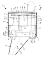
- an inventive silencer 1 a housing 2, in particular a cylindrical Has shape.
- the housing 2 comprises a jacket 3 as well an inlet bottom 4 and an outlet bottom 5.
- the housing 2 with an inlet funnel 6, extending from a Not shown exhaust pipe to the housing 2 expands out.
- the output side is the case 2 equipped with an outlet pipe 7, which also can lead to an exhaust pipe or its outlet end 8 (see Fig. 5) the exhaust gas outlet of an exhaust line, not shown forms, in which the muffler 1 is installed.
- This exhaust line belongs to an internal combustion engine and discharges their exhaust gases from their combustion chambers into the environment.
- this internal combustion engine is in one Motor vehicle, in particular in a commercial vehicle arranged.
- a catalyst 9 is integrated. To This purpose includes the muffler 1 in its housing. 2 at least one catalyst element 10. In the illustrated preferred Exemplary embodiments are several, here by way of example six, catalyst elements 10 are provided, in their entirety form the catalyst 9. Accordingly, the Catalyst 9 in the figures, each with a curly Bracket marked. These catalyst elements 10 can as carrier material optionally a ceramic or metal substrate exhibit.
- the catalyst elements 10 are arranged in the housing 2, that they can be flowed through in parallel.
- an inlet chamber 11 is formed, which via the inlet funnel 6, the exhaust gases are supplied.
- the Catalyst elements 10 are each with their inlet ends 12 connected to the inlet chamber 11.
- the catalyst elements 10 In the present Fall penetrate the catalyst elements 10 with their Inlet ends 12 a partition 13, which the inlet chamber 11 at a the inlet funnel 6 opposite Side closes.
- the catalyst elements 10 passed through this partition 13.
- This implementation through the partition 13 is designed gas-tight and in particular by means of a solder joint, not shown here or welded joint realized, the annular and closed the respective catalyst element 10 along the Partition 13 includes.
- Each catalyst element 10 opens with its respective Exit end 14 in an outlet chamber 15, on the one hand from the outlet bottom 5 and this opposite of another Partition 16 is limited.
- the catalyst elements 10 have at their outlet ends 14 each have an annular Perforation 17 up. This construction causes a damping of Gas pulsations in the outlet chamber 15. This succeeds it is to reduce the structure-borne sound excitation at the outlet bottom 5.
- the inlet chamber 11 is designed gas-tight, so that via the inlet funnel 6 supplied exhaust exclusively through the catalyst elements 10 again emerge from the inlet chamber 11 can. Due to the gas-tight design of the inlet chamber 11th may be the leakage of exhaust gas into the environment of the muffler 1 and a bypass of the catalyst elements 10, So escape into the collection chamber 18 can be avoided.
- Such a hermetically sealed inlet chamber 11 is for a preferred application form of the muffler 1 of particular Meaning, namely, if the integrated therein Catalyst 9 is designed as an SCR catalyst and the Conversion of urea or ammonia is used upstream of the muffler 1 is introduced into the exhaust system. For the design of an SCR catalyst 9 are accordingly SCR catalyst elements 10 used.
- the SCR technique that is to say by selective catalytic reaction or reduction, can reduce the NO x components in the exhaust gas to H 2 O and N 2 .
- the inlet chamber 11 is configured leak-free in the invention. This is achieved for example by the fact that in the embodiments of FIGS. 1 and 2, the inlet funnel 6 is connected to the inlet bottom 4 with at least one annular and closed circumferential along the inlet bottom 4, not shown here weld or solder joint.
- the partition wall 13 arranged between the inlet chamber 11 and the collection chamber 18 is sealed in a ring-shaped manner and is circumferentially sealed to the outside.
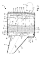
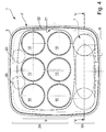
- the inlet chamber 11 in a separate inlet chamber housing 21st formed, which also in the cross section of FIG. 4 recognizable is.
- This separate inlet chamber housing 21 is as such completely inserted into the housing 2 of the muffler 1.
- the inlet chamber housing 21 also has a Jacket 22 and the output side through the partition 13th locked.
- On the input side is the inlet chamber housing 21 closed by the inlet bottom 4, with the rest Inlet bottom 4 'of the housing 2 connected, in particular tight is inserted therein.
- For the input-side closing of the Housing 2 is thus an additional, correspondingly shaped Inlet bottom 4 ⁇ required.
- an embodiment possible, in which the inlet chamber housing 21 and the housing 2 is closed by a common inlet bottom are and / or in the inlet chamber housing 21 a own outlet bottom has.
- the separately produced inlet chamber housing 21 leaves In particular, simply prefabricate, whereby the desired Tightness for the inlet chamber 11 relatively inexpensive is feasible.
- the inlet funnel 6 is on this inlet chamber housing 21 is grown, so that an outlet end 23 of the inlet funnel 6 in the inlet chamber 11 opens.
- the catalyst elements 10 extend with their entry ends 12 to the outlet end 23 of the inlet funnel 6.
- the inlet funnel 6 quasi the inlet bottom of the inlet chamber housing 21 make or dispensable.
- a distributor and / or mixing element 25 may be arranged, the shown here with a broken line.
- This distributor and / or mixing element 25 supports, for example the expansion of the incoming exhaust gas flow and allows a uniform flow of the individual inlet ends 12 of the catalyst elements 10. It is clear that Such a distribution and / or mixing element 25 also at the embodiments of FIGS. 1 and 2 in the inlet funnel. 6 can be arranged.
- the inlet chamber 11 designed comparatively large volume, which in the Entry chamber 11 a relatively homogeneous mixing and a comparatively even distribution of the incoming Exhaust gases on the individual catalyst elements 10 can be realized is.
- the inlet chamber 11 may be smaller in size.
- Damping chamber 26 is formed in the one through a Hatching indicated damping material 27 is arranged. This damping chamber 26 is e.g. between the inlet chamber 11 and the outlet chamber 15 and also appropriate disposed between the inlet chamber 11 and the collection chamber 18.
- a further partition wall 28 is provided, which the collection chamber 18 of the damping chamber 26 separates. If - as in the embodiment of FIG. 2 - An inlet chamber housing 21 is provided, can the damping chamber 26 within the housing 2 also side of the inlet chamber housing 21 to the inlet bottom 4 ⁇ extend.
- FIG. 4 This is exemplified by a multi-layered Construction of the muffler 2 allows for what special clearly apparent from Fig. 4.
- the housing 2 at least in the region of the inlet chamber housing 21 in two levels, namely in a catalyst plane 29 and in a Outlet tube level 30, divided.
- the catalyst 9 or are its catalyst elements 10 Within the catalyst level 29 is the catalyst 9 or are its catalyst elements 10, while in the outlet tube 30th the outlet pipe 7 is arranged. 4 extends the outlet tube 7 thus below the catalyst 9 and below the catalyst elements 10 and thus also below the inlet chamber housing 21, if any is.
- This design results in greater freedom for the design and installation of the outlet tube 7, so that this be optimized in particular with regard to its length can.
- the outlet pipe 7 extends starting at its entry end 19 with a first section 31 in the collection chamber 18, in a second section 32 in the damping chamber 26 and with a third portion 33rd again in the collection chamber 18 and in the exit chamber 15, from where the outlet pipe 7 from the housing 2, through the Outlet bottom 5 exits and ends at the outlet end 8.
- the in arranged the collection chamber 18 and the entrance end 19th having first portion 31 is with a perforation 34th provided here schematically indicated with few breakthroughs is.
- This perforation 34 allows the inflow of exhaust gas from the collection chamber 18 in the outlet pipe. 7 in addition to the open entrance end 19.
- the entrance end 19 is relatively close to the partition wall 16 between the collection chamber 18 and outlet chamber 15 positioned, whereby a particularly large outlet tube length can be achieved, which is the Damping effect of the muffler 1 in the low-frequency range improved.
- the extending in the damping chamber 26 is also second section 32 of the outlet tube 7 with a Perforation 35 provided, which also only by some Breakthroughs is indicated. It is remarkable that the perforation 35 of the outlet tube 7 in the damping chamber 26 is not for a gas exchange, but for a Sound exit from the outlet pipe 7 in the damping chamber 26 is provided. In this way, the entrained in the exhaust gas Airborne sound in the damping chamber 26 and there in the Damper material 27 penetrate, resulting in an effective Can achieve damping of airborne sound. According to her different functions are the perforations 34 and 35 of the two pipe sections 31 and 32 different dimensioned. So are the opening cross sections at the perforation 34 of the first pipe section 31 within the collection chamber 18 larger dimensions than those of the perforation 35 of the second pipe section 32 within the damping chamber 26th
- the muffler 1 according to the invention also has a reduced structure-borne sound radiation to the outside and one improved heat balance.
- This is achieved by a double-walled design of the housing 2.
- the jacket 3 double-walled, so with two individual walls 3a and 3b configured, wherein between the individual walls 3a, 3b a Insulation liner 36 is arranged.
- This insulation insert 36 is mainly used for thermal insulation and can additionally be designed sound-absorbing.
- Analogous is also the inlet bottom 4 double-walled, so with two individual walls 4a and 4b configured. It is also between the Single walls 4a and 4b of the inlet floor 4 a corresponding Insulation insert 36 introduced.
- FIGS. 1 and 2 and the jacket 22nd the inlet chamber housing 21 designed double-walled. Between the individual walls 22a and 22b of the shell 22 is located then again a corresponding insulation insert 36.
- Figs. 1 to 3 is further the inlet funnel 6 double-walled designed so that a jacket 37 of the Inlet funnel 6 between its individual walls 37a and 37b again receives a suitable insulating liner 36.
- the housing 2 in addition to the Entry chamber housing 21, that is substantially in the Auslressebene 30 contain a further chamber 39, the of the adjacent damping chamber 26 by another Partition 38 is separated.
- this additional chamber 39 it can be another damping chamber, the Accordingly, it can be filled with damping material 27.
- the partition wall 38 may be perforated. It essentially serves for fixing the position of the outlet tube 7 and the inlet chamber housing 21 in the housing 2.
- the silencer 1 according to the invention with integrated catalyst 9 works as follows:
- the exhaust gases flow through the inlet funnel 6 in the inlet chamber 11 a.
- the exhaust gases can be treated with urea or be enriched with ammonia.
- the exhaust gases are distributed as evenly as possible on the inlet ends 12 of the catalyst elements 10. Since the Entry chamber 11 according to the invention designed leak-free is, there is no other possibility for the exhaust gases Leave entry chamber 11. Thus, all flow through Exhaust gases, the catalyst elements 10th
- the exhaust gases get into the Exit chamber 15. From the outlet chamber 15 enter the Exhaust gases through the partition 16 into the collection chamber 18. Von the collection chamber 18 pass the exhaust gases through the inlet end 19 and through the perforation 34 in the outlet pipe. 7 Through the outlet pipe 7, the exhaust gases from the housing. 2 led out.
- the perforation 35 within the sound attenuation chamber 26 allows a sound in the Damping material 27, which in particular higher interference frequencies be absorbed.
Landscapes
- Chemical & Material Sciences (AREA)
- Engineering & Computer Science (AREA)
- Chemical Kinetics & Catalysis (AREA)
- Combustion & Propulsion (AREA)
- Mechanical Engineering (AREA)
- General Engineering & Computer Science (AREA)
- Health & Medical Sciences (AREA)
- Toxicology (AREA)
- Exhaust Gas After Treatment (AREA)
- Exhaust Silencers (AREA)
Applications Claiming Priority (2)
| Application Number | Priority Date | Filing Date | Title |
|---|---|---|---|
| DE10356000A DE10356000B4 (de) | 2003-11-27 | 2003-11-27 | Schalldämpfer mit integriertem Katalysator |
| DE10356000 | 2003-11-27 |
Publications (3)
| Publication Number | Publication Date |
|---|---|
| EP1536113A2 true EP1536113A2 (fr) | 2005-06-01 |
| EP1536113A3 EP1536113A3 (fr) | 2006-03-15 |
| EP1536113B1 EP1536113B1 (fr) | 2008-08-13 |
Family
ID=34442371
Family Applications (1)
| Application Number | Title | Priority Date | Filing Date |
|---|---|---|---|
| EP04105619A Expired - Lifetime EP1536113B1 (fr) | 2003-11-27 | 2004-11-09 | Silencieux d'échappement avec catalyseur intégré |
Country Status (4)
| Country | Link |
|---|---|
| US (1) | US7127884B2 (fr) |
| EP (1) | EP1536113B1 (fr) |
| AT (1) | ATE404781T1 (fr) |
| DE (2) | DE10356000B4 (fr) |
Cited By (6)
| Publication number | Priority date | Publication date | Assignee | Title |
|---|---|---|---|---|
| DE102005025738A1 (de) * | 2005-06-04 | 2006-12-21 | Daimlerchrysler Ag | Abgasnachbehandlungsvorrichtung |
| WO2008107151A1 (fr) * | 2007-03-03 | 2008-09-12 | Eberspächer Unna GmbH & Co. KG | Dispositif de post-traitement des gaz d'échappement d'un véhicule automobile |
| DE102008046222A1 (de) * | 2008-09-08 | 2010-04-08 | J. Eberspächer GmbH & Co. KG | Abgasnachbehandlungseinrichtung |
| US8763375B2 (en) | 2010-08-19 | 2014-07-01 | J. Eberspaecher Gmbh & Co. Kg | Exhaust gas cleaning device, exhaust system, removal method |
| US9222392B2 (en) | 2010-04-15 | 2015-12-29 | Eberspaecher Exhaust Technology Gmbh & Co. Kg | Exhaust gas treatment device |
| IT201700008995A1 (it) * | 2017-02-16 | 2018-08-16 | Xxl Marmitte Italiane S R L | Catalizzatore per mezzi pesanti |
Families Citing this family (31)
| Publication number | Priority date | Publication date | Assignee | Title |
|---|---|---|---|---|
| DE102004038188A1 (de) * | 2004-08-06 | 2006-03-16 | Robert Bosch Gmbh | Schalldämpfungseinrichtung, insbesondere für ein Heizgerät |
| US20060081416A1 (en) * | 2004-10-14 | 2006-04-20 | Nentrup Trent L | Exhaust silencer with acoustic damping mat |
| JP2006151298A (ja) * | 2004-11-30 | 2006-06-15 | Honda Motor Co Ltd | 燃料電池自動車 |
| KR100667028B1 (ko) * | 2005-10-04 | 2007-01-10 | 희성엥겔하드주식회사 | 환원제 무주입 scr 촉매컨버터 |
| US20070290510A1 (en) * | 2006-06-16 | 2007-12-20 | Aratari Robert | Combustion Generator Enhancement Device |
| US7717205B2 (en) * | 2006-11-28 | 2010-05-18 | Caterpillar Inc. | Engine hood assembly enclosure with exhaust aftertreatment device integrated therein, and machine using same |
| DE102008022081A1 (de) * | 2008-05-05 | 2009-11-12 | J. Eberspächer GmbH & Co. KG | Abgasbehandlungseinrichtung |
| US8071037B2 (en) | 2008-06-25 | 2011-12-06 | Cummins Filtration Ip, Inc. | Catalytic devices for converting urea to ammonia |
| US20100186394A1 (en) * | 2009-01-26 | 2010-07-29 | Caterpillar Inc. | Exhaust gas after treatment assembly |
| US20100186381A1 (en) * | 2009-01-26 | 2010-07-29 | Caterpillar Inc | Exhaust system thermal enclosure |
| DE102009024718A1 (de) * | 2009-06-12 | 2010-12-16 | Emitec Gesellschaft Für Emissionstechnologie Mbh | Abgasbehandlungsvorrichtung für den motornahen Einsatz |
| US8151556B2 (en) * | 2009-07-21 | 2012-04-10 | Navistar Canada, Inc. | Internal combustion engine exhaust after-treatment system and method |
| DE102010008999A1 (de) * | 2010-02-24 | 2011-08-25 | J. Eberspächer GmbH & Co. KG, 73730 | Abgasbehandlungseinrichtung |
| AT511548A1 (de) * | 2011-06-06 | 2012-12-15 | Avl List Gmbh | Brennkraftmaschine mit zumindest einer katalysatoreinheit |
| US9086007B2 (en) * | 2012-12-21 | 2015-07-21 | Caterpillar Inc. | System and method for accommodating aftertreatment bricks |
| US8978369B2 (en) | 2012-12-26 | 2015-03-17 | Caterpillar Inc. | Exhaust gas aftertreatment module |
| US9828898B2 (en) * | 2015-10-29 | 2017-11-28 | Hyundai Motor Company | Optimized structure for integrated catalytic muffler |
| JP6522032B2 (ja) * | 2017-03-23 | 2019-05-29 | 本田技研工業株式会社 | 排気装置 |
| US11136910B2 (en) | 2017-06-06 | 2021-10-05 | Cummins Emission Solutions Inc. | Systems and methods for mixing exhaust gases and reductant in an aftertreatment system |
| EP3688289A4 (fr) | 2017-09-25 | 2021-03-24 | Faurecia Emissions Control Technologies, USA, LLC | Volume acoustique au niveau de l'extrémité chaude de systèmes d'échappement |
| US10941693B2 (en) | 2018-01-18 | 2021-03-09 | Faurecia Emissions Control Technologies, Usa, Llc | Vehicle frame with acoustic volume for an exhaust system |
| EP4069954A4 (fr) | 2019-12-03 | 2023-08-09 | Cummins Emission Solutions Inc. | Système de distribution de réducteur pour système de post-traitement de gaz d'échappement |
| WO2021173357A1 (fr) | 2020-02-27 | 2021-09-02 | Cummins Emission Solutions Inc. | Mélangeurs destinés à être utilisés dans des systèmes de post-traitement |
| US12173632B2 (en) | 2020-10-22 | 2024-12-24 | Cummins Emission Solutions Inc. | Exhaust gas aftertreatment system |
| US12352196B2 (en) | 2021-02-02 | 2025-07-08 | Cummins Emission Solutions Inc. | Exhaust gas aftertreatment system |
| US12123337B2 (en) | 2021-03-18 | 2024-10-22 | Cummins Emission Solutions Inc. | Aftertreatment systems |
| CN117396668A (zh) | 2021-07-27 | 2024-01-12 | 康明斯排放处理公司 | 废气后处理系统 |
| CN119643152A (zh) | 2021-08-23 | 2025-03-18 | 康明斯排放处理公司 | 用于后处理系统的出口取样系统 |
| DE102021130365B8 (de) | 2021-11-19 | 2023-05-04 | Emission Partner GmbH & Co. KG | Abgasanlage |
| USD1042544S1 (en) | 2022-04-21 | 2024-09-17 | Cummins Emission Solutions Inc. | Aftertreatment system |
| USD1042545S1 (en) | 2022-04-21 | 2024-09-17 | Cummins Emission Solutions Inc. | Aftertreatment system |
Family Cites Families (16)
| Publication number | Priority date | Publication date | Assignee | Title |
|---|---|---|---|---|
| US4209493A (en) * | 1977-07-11 | 1980-06-24 | Nelson Industries, Inc. | Combination catalytic converter and muffler for an exhaust system |
| JPS60184919A (ja) * | 1984-03-01 | 1985-09-20 | Nissan Motor Co Ltd | 内燃機関用触媒マフラ−装置 |
| DE3729477C3 (de) * | 1987-09-03 | 1999-09-09 | Stihl Maschf Andreas | Abgasschalldämpfer für Zweitaktmotoren, insbesondere für tragbare Arbeitsgeräte wie Motorkettensägen |
| DE3940747C1 (fr) * | 1989-12-09 | 1990-07-12 | Mercedes-Benz Aktiengesellschaft, 7000 Stuttgart, De | |
| DE4219540B4 (de) * | 1991-06-28 | 2008-02-28 | Volkswagen Ag | Katalysatoranordnung für die Reinigung eines pulsierenden Abgasstromes |
| DE4219549C2 (de) | 1992-06-15 | 1994-07-28 | Fraunhofer Ges Forschung | Verfahren zum Schweißen von Werkstücken |
| US5285640A (en) * | 1992-07-21 | 1994-02-15 | Olivo John R | Integrated post-engine emissions heater, catalytic converter and muffler |
| DE4431484C2 (de) * | 1994-09-03 | 1997-04-17 | Eberspaecher J | Schalldämpfer mit integrierter Abgasreinigungsstufe |
| DK0835160T3 (da) * | 1995-06-28 | 2000-10-09 | Siemens Ag | Fremgangsmåde og indretning til katalytisk rensning af røggas fra et forbræningsanlæg |
| DE19626980A1 (de) * | 1996-07-04 | 1998-02-26 | Roth Technik Austria | Schalldämpfer für Kraftfahrzeuge |
| DE19952428A1 (de) * | 1999-10-30 | 2001-05-03 | Man Nutzfahrzeuge Ag | Verfahren und Vorrichtung zur kombinierten katalytischen NOx-Reduktion und Schalldämpfung von Abgas im Abgasstrang einer Brennkraftmaschine |
| DE10042542A1 (de) * | 2000-08-30 | 2002-03-14 | Eberspaecher J Gmbh & Co | Abgasreinigungssystem für Kraftfahrzeuge, insbesondere Diesel-Nutzfahrzeuge |
| EP1366274A1 (fr) * | 2001-02-07 | 2003-12-03 | Paulo T. Lage | Processeur d'echappement equipe d'un eliminateur de particules remplacable |
| JP2002256861A (ja) * | 2001-03-05 | 2002-09-11 | Honda Motor Co Ltd | 触媒付マフラー装置 |
| DE10123360A1 (de) * | 2001-05-14 | 2002-11-21 | Man Nutzfahrzeuge Ag | Kombinierte Abgasnachbehandlungs-/Schalldämpfungsvorrichtung im Abgasstrang einer Brennkraftmaschine |
| GB0113226D0 (en) * | 2001-06-01 | 2001-07-25 | Nelson Burgess Ltd | Catalytic converter |
-
2003
- 2003-11-27 DE DE10356000A patent/DE10356000B4/de not_active Expired - Fee Related
-
2004
- 2004-11-09 EP EP04105619A patent/EP1536113B1/fr not_active Expired - Lifetime
- 2004-11-09 AT AT04105619T patent/ATE404781T1/de not_active IP Right Cessation
- 2004-11-09 DE DE502004007827T patent/DE502004007827D1/de not_active Expired - Lifetime
- 2004-11-24 US US10/996,378 patent/US7127884B2/en not_active Expired - Lifetime
Cited By (9)
| Publication number | Priority date | Publication date | Assignee | Title |
|---|---|---|---|---|
| DE102005025738A1 (de) * | 2005-06-04 | 2006-12-21 | Daimlerchrysler Ag | Abgasnachbehandlungsvorrichtung |
| WO2008107151A1 (fr) * | 2007-03-03 | 2008-09-12 | Eberspächer Unna GmbH & Co. KG | Dispositif de post-traitement des gaz d'échappement d'un véhicule automobile |
| US8549844B2 (en) | 2007-03-03 | 2013-10-08 | Eberspächer Exhaust Technology GmbH & Co. KG | Exhaust gas after treatment apparatus of a motor vehicle |
| DE102008046222A1 (de) * | 2008-09-08 | 2010-04-08 | J. Eberspächer GmbH & Co. KG | Abgasnachbehandlungseinrichtung |
| US8388896B2 (en) | 2008-09-08 | 2013-03-05 | J. Eberspaecher Gmbh & Co. Kg | Exhaust gas retreatment device |
| DE102008046222B4 (de) | 2008-09-08 | 2024-06-06 | Purem GmbH | Abgasnachbehandlungseinrichtung |
| US9222392B2 (en) | 2010-04-15 | 2015-12-29 | Eberspaecher Exhaust Technology Gmbh & Co. Kg | Exhaust gas treatment device |
| US8763375B2 (en) | 2010-08-19 | 2014-07-01 | J. Eberspaecher Gmbh & Co. Kg | Exhaust gas cleaning device, exhaust system, removal method |
| IT201700008995A1 (it) * | 2017-02-16 | 2018-08-16 | Xxl Marmitte Italiane S R L | Catalizzatore per mezzi pesanti |
Also Published As
| Publication number | Publication date |
|---|---|
| EP1536113B1 (fr) | 2008-08-13 |
| DE10356000B4 (de) | 2006-01-12 |
| US7127884B2 (en) | 2006-10-31 |
| EP1536113A3 (fr) | 2006-03-15 |
| ATE404781T1 (de) | 2008-08-15 |
| US20050115229A1 (en) | 2005-06-02 |
| DE502004007827D1 (de) | 2008-09-25 |
| DE10356000A1 (de) | 2005-07-07 |
Similar Documents
| Publication | Publication Date | Title |
|---|---|---|
| DE10356000B4 (de) | Schalldämpfer mit integriertem Katalysator | |
| EP1691045B1 (fr) | Système de purification des gaz d'échappement | |
| DE112008002531B4 (de) | Abgasnachbehandlungssystem | |
| EP2233708B2 (fr) | Dispositif de traitement des gaz d'échappement | |
| EP1357267B1 (fr) | Système de ligne d'échappement avec silencieux pour un moteur diesel | |
| DE102008046222B4 (de) | Abgasnachbehandlungseinrichtung | |
| DE102005025045A1 (de) | Abgasanlage | |
| DE19900310B4 (de) | Katalytischer Konverter für einen Schalldämpfer eines Kleinmotors | |
| DE102007010486A1 (de) | Abgasnachbehandlungseinrichtung eines Kraftfahrzeugs | |
| DE19755126B4 (de) | Katalysatoranordnung mit zweisträngiger Abgasführung | |
| DE60018201T2 (de) | Vorrichtung zur selektiven kühlung von abgas eines kraftfahrzeugmotors | |
| DE19626980A1 (de) | Schalldämpfer für Kraftfahrzeuge | |
| EP3704360B1 (fr) | Installation de gaz d'échappement pour le post-traitement et l'atténuation des sons de gaz d'échappement, de manière compacte et efficace | |
| DE102011120221A1 (de) | Mischer für eine Abgasanlage und Abgasanlage | |
| DE10144015A1 (de) | Abgasanlage für mehrzylindrige Verbrennungsmotoren | |
| DE2022037A1 (de) | Schalldaempfer | |
| DE60214748T2 (de) | In einem abgassystem für einen verbrennungsmotor angeordnetes gehäuse | |
| DE1426198A1 (de) | Schalldaempfer | |
| DE10357941B4 (de) | Schalldämpfer für eine Abgasanlage | |
| EP4183986B1 (fr) | Système d'échappement | |
| DE29512732U1 (de) | Schalldämpfer für die Abgasanlage eines Verbrennungsmotors | |
| DE102018203300B4 (de) | Anordnung einer Brennkraftmaschine mit einem Abgastrakt, Kraftfahrzeug sowie Verfahren zum Steuern einer Abgasnachbehandlung | |
| EP3759327B1 (fr) | Dispositif pour le traitment des gaz d'échappement | |
| DE20116088U1 (de) | Abgasanlage | |
| EP1749686B1 (fr) | Système d'échappement pour véhicule automobile |
Legal Events
| Date | Code | Title | Description |
|---|---|---|---|
| PUAI | Public reference made under article 153(3) epc to a published international application that has entered the european phase |
Free format text: ORIGINAL CODE: 0009012 |
|
| AK | Designated contracting states |
Kind code of ref document: A2 Designated state(s): AT BE BG CH CY CZ DE DK EE ES FI FR GB GR HU IE IS IT LI LU MC NL PL PT RO SE SI SK TR |
|
| AX | Request for extension of the european patent |
Extension state: AL HR LT LV MK YU |
|
| PUAL | Search report despatched |
Free format text: ORIGINAL CODE: 0009013 |
|
| AK | Designated contracting states |
Kind code of ref document: A3 Designated state(s): AT BE BG CH CY CZ DE DK EE ES FI FR GB GR HU IE IS IT LI LU MC NL PL PT RO SE SI SK TR |
|
| AX | Request for extension of the european patent |
Extension state: AL HR LT LV MK YU |
|
| 17P | Request for examination filed |
Effective date: 20060330 |
|
| AKX | Designation fees paid |
Designated state(s): AT BE BG CH CY CZ DE DK EE ES FI FR GB GR HU IE IS IT LI LU MC NL PL PT RO SE SI SK TR |
|
| 17Q | First examination report despatched |
Effective date: 20061130 |
|
| GRAP | Despatch of communication of intention to grant a patent |
Free format text: ORIGINAL CODE: EPIDOSNIGR1 |
|
| GRAC | Information related to communication of intention to grant a patent modified |
Free format text: ORIGINAL CODE: EPIDOSCIGR1 |
|
| GRAS | Grant fee paid |
Free format text: ORIGINAL CODE: EPIDOSNIGR3 |
|
| GRAA | (expected) grant |
Free format text: ORIGINAL CODE: 0009210 |
|
| AK | Designated contracting states |
Kind code of ref document: B1 Designated state(s): AT BE BG CH CY CZ DE DK EE ES FI FR GB GR HU IE IS IT LI LU MC NL PL PT RO SE SI SK TR |
|
| REG | Reference to a national code |
Ref country code: GB Ref legal event code: FG4D Free format text: NOT ENGLISH |
|
| REG | Reference to a national code |
Ref country code: CH Ref legal event code: EP |
|
| REG | Reference to a national code |
Ref country code: IE Ref legal event code: FG4D Free format text: LANGUAGE OF EP DOCUMENT: GERMAN |
|
| REF | Corresponds to: |
Ref document number: 502004007827 Country of ref document: DE Date of ref document: 20080925 Kind code of ref document: P |
|
| REG | Reference to a national code |
Ref country code: SE Ref legal event code: TRGR |
|
| PG25 | Lapsed in a contracting state [announced via postgrant information from national office to epo] |
Ref country code: ES Free format text: LAPSE BECAUSE OF FAILURE TO SUBMIT A TRANSLATION OF THE DESCRIPTION OR TO PAY THE FEE WITHIN THE PRESCRIBED TIME-LIMIT Effective date: 20081124 Ref country code: IS Free format text: LAPSE BECAUSE OF FAILURE TO SUBMIT A TRANSLATION OF THE DESCRIPTION OR TO PAY THE FEE WITHIN THE PRESCRIBED TIME-LIMIT Effective date: 20081213 |
|
| PG25 | Lapsed in a contracting state [announced via postgrant information from national office to epo] |
Ref country code: SI Free format text: LAPSE BECAUSE OF FAILURE TO SUBMIT A TRANSLATION OF THE DESCRIPTION OR TO PAY THE FEE WITHIN THE PRESCRIBED TIME-LIMIT Effective date: 20080813 Ref country code: FI Free format text: LAPSE BECAUSE OF FAILURE TO SUBMIT A TRANSLATION OF THE DESCRIPTION OR TO PAY THE FEE WITHIN THE PRESCRIBED TIME-LIMIT Effective date: 20080813 |
|
| REG | Reference to a national code |
Ref country code: IE Ref legal event code: FD4D |
|
| PG25 | Lapsed in a contracting state [announced via postgrant information from national office to epo] |
Ref country code: BG Free format text: LAPSE BECAUSE OF FAILURE TO SUBMIT A TRANSLATION OF THE DESCRIPTION OR TO PAY THE FEE WITHIN THE PRESCRIBED TIME-LIMIT Effective date: 20081113 Ref country code: DK Free format text: LAPSE BECAUSE OF FAILURE TO SUBMIT A TRANSLATION OF THE DESCRIPTION OR TO PAY THE FEE WITHIN THE PRESCRIBED TIME-LIMIT Effective date: 20080813 Ref country code: IE Free format text: LAPSE BECAUSE OF FAILURE TO SUBMIT A TRANSLATION OF THE DESCRIPTION OR TO PAY THE FEE WITHIN THE PRESCRIBED TIME-LIMIT Effective date: 20080813 |
|
| PG25 | Lapsed in a contracting state [announced via postgrant information from national office to epo] |
Ref country code: RO Free format text: LAPSE BECAUSE OF FAILURE TO SUBMIT A TRANSLATION OF THE DESCRIPTION OR TO PAY THE FEE WITHIN THE PRESCRIBED TIME-LIMIT Effective date: 20080813 Ref country code: PT Free format text: LAPSE BECAUSE OF FAILURE TO SUBMIT A TRANSLATION OF THE DESCRIPTION OR TO PAY THE FEE WITHIN THE PRESCRIBED TIME-LIMIT Effective date: 20090113 Ref country code: CZ Free format text: LAPSE BECAUSE OF FAILURE TO SUBMIT A TRANSLATION OF THE DESCRIPTION OR TO PAY THE FEE WITHIN THE PRESCRIBED TIME-LIMIT Effective date: 20080813 Ref country code: SK Free format text: LAPSE BECAUSE OF FAILURE TO SUBMIT A TRANSLATION OF THE DESCRIPTION OR TO PAY THE FEE WITHIN THE PRESCRIBED TIME-LIMIT Effective date: 20080813 |
|
| BERE | Be: lapsed |
Owner name: J. EBERSPACHER G.M.B.H. & CO. KG Effective date: 20081130 |
|
| PLBE | No opposition filed within time limit |
Free format text: ORIGINAL CODE: 0009261 |
|
| STAA | Information on the status of an ep patent application or granted ep patent |
Free format text: STATUS: NO OPPOSITION FILED WITHIN TIME LIMIT |
|
| PG25 | Lapsed in a contracting state [announced via postgrant information from national office to epo] |
Ref country code: MC Free format text: LAPSE BECAUSE OF NON-PAYMENT OF DUE FEES Effective date: 20081130 |
|
| REG | Reference to a national code |
Ref country code: CH Ref legal event code: PL |
|
| 26N | No opposition filed |
Effective date: 20090514 |
|
| PG25 | Lapsed in a contracting state [announced via postgrant information from national office to epo] |
Ref country code: EE Free format text: LAPSE BECAUSE OF FAILURE TO SUBMIT A TRANSLATION OF THE DESCRIPTION OR TO PAY THE FEE WITHIN THE PRESCRIBED TIME-LIMIT Effective date: 20080813 |
|
| PG25 | Lapsed in a contracting state [announced via postgrant information from national office to epo] |
Ref country code: IT Free format text: LAPSE BECAUSE OF FAILURE TO SUBMIT A TRANSLATION OF THE DESCRIPTION OR TO PAY THE FEE WITHIN THE PRESCRIBED TIME-LIMIT Effective date: 20080813 |
|
| PG25 | Lapsed in a contracting state [announced via postgrant information from national office to epo] |
Ref country code: BE Free format text: LAPSE BECAUSE OF NON-PAYMENT OF DUE FEES Effective date: 20081130 |
|
| PG25 | Lapsed in a contracting state [announced via postgrant information from national office to epo] |
Ref country code: CH Free format text: LAPSE BECAUSE OF NON-PAYMENT OF DUE FEES Effective date: 20081130 Ref country code: LI Free format text: LAPSE BECAUSE OF NON-PAYMENT OF DUE FEES Effective date: 20081130 |
|
| PG25 | Lapsed in a contracting state [announced via postgrant information from national office to epo] |
Ref country code: AT Free format text: LAPSE BECAUSE OF NON-PAYMENT OF DUE FEES Effective date: 20081109 |
|
| PG25 | Lapsed in a contracting state [announced via postgrant information from national office to epo] |
Ref country code: PL Free format text: LAPSE BECAUSE OF FAILURE TO SUBMIT A TRANSLATION OF THE DESCRIPTION OR TO PAY THE FEE WITHIN THE PRESCRIBED TIME-LIMIT Effective date: 20080813 |
|
| PG25 | Lapsed in a contracting state [announced via postgrant information from national office to epo] |
Ref country code: LU Free format text: LAPSE BECAUSE OF NON-PAYMENT OF DUE FEES Effective date: 20081109 Ref country code: CY Free format text: LAPSE BECAUSE OF FAILURE TO SUBMIT A TRANSLATION OF THE DESCRIPTION OR TO PAY THE FEE WITHIN THE PRESCRIBED TIME-LIMIT Effective date: 20080813 Ref country code: HU Free format text: LAPSE BECAUSE OF FAILURE TO SUBMIT A TRANSLATION OF THE DESCRIPTION OR TO PAY THE FEE WITHIN THE PRESCRIBED TIME-LIMIT Effective date: 20090214 |
|
| PG25 | Lapsed in a contracting state [announced via postgrant information from national office to epo] |
Ref country code: TR Free format text: LAPSE BECAUSE OF FAILURE TO SUBMIT A TRANSLATION OF THE DESCRIPTION OR TO PAY THE FEE WITHIN THE PRESCRIBED TIME-LIMIT Effective date: 20080813 |
|
| PG25 | Lapsed in a contracting state [announced via postgrant information from national office to epo] |
Ref country code: GR Free format text: LAPSE BECAUSE OF FAILURE TO SUBMIT A TRANSLATION OF THE DESCRIPTION OR TO PAY THE FEE WITHIN THE PRESCRIBED TIME-LIMIT Effective date: 20081114 |
|
| REG | Reference to a national code |
Ref country code: GB Ref legal event code: 732E Free format text: REGISTERED BETWEEN 20130905 AND 20130911 |
|
| REG | Reference to a national code |
Ref country code: DE Ref legal event code: R082 Ref document number: 502004007827 Country of ref document: DE Representative=s name: BRP RENAUD & PARTNER, DE |
|
| REG | Reference to a national code |
Ref country code: DE Ref legal event code: R081 Ref document number: 502004007827 Country of ref document: DE Owner name: EBERSPAECHER EXHAUST TECHNOLOGY GMBH & CO. KG, DE Free format text: FORMER OWNER: J. EBERSPAECHER GMBH & CO. KG, 73730 ESSLINGEN, DE Effective date: 20131022 Ref country code: DE Ref legal event code: R082 Ref document number: 502004007827 Country of ref document: DE Representative=s name: BRP RENAUD & PARTNER, DE Effective date: 20131022 Ref country code: DE Ref legal event code: R082 Ref document number: 502004007827 Country of ref document: DE Representative=s name: BRP RENAUD UND PARTNER MBB RECHTSANWAELTE PATE, DE Effective date: 20131022 Ref country code: DE Ref legal event code: R082 Ref document number: 502004007827 Country of ref document: DE Representative=s name: BRP RENAUD UND PARTNER MBB, DE Effective date: 20131022 |
|
| REG | Reference to a national code |
Ref country code: FR Ref legal event code: CD Owner name: EBERSPACHER CLIMATE CONTROL SYSTEMS GMBH & CO. KG Effective date: 20131129 |
|
| REG | Reference to a national code |
Ref country code: FR Ref legal event code: TP Owner name: EBERSPACHER EXHAUST TECHNOLOGY GMBH & CO. KG, DE Effective date: 20140204 |
|
| REG | Reference to a national code |
Ref country code: NL Ref legal event code: TD Effective date: 20150609 Ref country code: NL Ref legal event code: SD Effective date: 20150609 |
|
| REG | Reference to a national code |
Ref country code: FR Ref legal event code: PLFP Year of fee payment: 12 |
|
| REG | Reference to a national code |
Ref country code: FR Ref legal event code: PLFP Year of fee payment: 13 |
|
| REG | Reference to a national code |
Ref country code: FR Ref legal event code: PLFP Year of fee payment: 14 |
|
| REG | Reference to a national code |
Ref country code: DE Ref legal event code: R081 Ref document number: 502004007827 Country of ref document: DE Owner name: PUREM GMBH, DE Free format text: FORMER OWNER: EBERSPAECHER EXHAUST TECHNOLOGY GMBH & CO. KG, 66539 NEUNKIRCHEN, DE |
|
| PGFP | Annual fee paid to national office [announced via postgrant information from national office to epo] |
Ref country code: SE Payment date: 20211123 Year of fee payment: 18 Ref country code: NL Payment date: 20211119 Year of fee payment: 18 |
|
| REG | Reference to a national code |
Ref country code: NL Ref legal event code: PD Owner name: EBERSPAECHER EXHAUST TECHNOLOGY GMBH; DE Free format text: DETAILS ASSIGNMENT: CHANGE OF OWNER(S), CHANGE OF LEGAL ENTITY; FORMER OWNER NAME: EBERSPAECHER EXHAUST TECHNOLOGY GMBH & CO. KG Effective date: 20221110 Ref country code: NL Ref legal event code: HC Owner name: PUREM GMBH; DE Free format text: DETAILS ASSIGNMENT: CHANGE OF OWNER(S), CHANGE OF OWNER(S) NAME; FORMER OWNER NAME: EBERSPAECHER EXHAUST TECHNOLOGY GMBH Effective date: 20221110 |
|
| REG | Reference to a national code |
Ref country code: SE Ref legal event code: EUG |
|
| REG | Reference to a national code |
Ref country code: NL Ref legal event code: MM Effective date: 20221201 |
|
| PG25 | Lapsed in a contracting state [announced via postgrant information from national office to epo] |
Ref country code: SE Free format text: LAPSE BECAUSE OF NON-PAYMENT OF DUE FEES Effective date: 20221110 Ref country code: NL Free format text: LAPSE BECAUSE OF NON-PAYMENT OF DUE FEES Effective date: 20221201 |
|
| PGFP | Annual fee paid to national office [announced via postgrant information from national office to epo] |
Ref country code: GB Payment date: 20231123 Year of fee payment: 20 |
|
| PGFP | Annual fee paid to national office [announced via postgrant information from national office to epo] |
Ref country code: FR Payment date: 20231124 Year of fee payment: 20 Ref country code: DE Payment date: 20231120 Year of fee payment: 20 |
|
| REG | Reference to a national code |
Ref country code: DE Ref legal event code: R071 Ref document number: 502004007827 Country of ref document: DE |
|
| REG | Reference to a national code |
Ref country code: GB Ref legal event code: PE20 Expiry date: 20241108 |
|
| PG25 | Lapsed in a contracting state [announced via postgrant information from national office to epo] |
Ref country code: GB Free format text: LAPSE BECAUSE OF EXPIRATION OF PROTECTION Effective date: 20241108 |
|
| PG25 | Lapsed in a contracting state [announced via postgrant information from national office to epo] |
Ref country code: GB Free format text: LAPSE BECAUSE OF EXPIRATION OF PROTECTION Effective date: 20241108 |