EP1536117A2 - Moteur à explosion par impulsion et installation avec pré-conditionnement de combustible - Google Patents
Moteur à explosion par impulsion et installation avec pré-conditionnement de combustible Download PDFInfo
- Publication number
- EP1536117A2 EP1536117A2 EP04257274A EP04257274A EP1536117A2 EP 1536117 A2 EP1536117 A2 EP 1536117A2 EP 04257274 A EP04257274 A EP 04257274A EP 04257274 A EP04257274 A EP 04257274A EP 1536117 A2 EP1536117 A2 EP 1536117A2
- Authority
- EP
- European Patent Office
- Prior art keywords
- fuel
- power system
- pulse detonation
- conditioner
- turbine
- Prior art date
- Legal status (The legal status is an assumption and is not a legal conclusion. Google has not performed a legal analysis and makes no representation as to the accuracy of the status listed.)
- Withdrawn
Links
- 239000000446 fuel Substances 0.000 title claims abstract description 156
- 238000005474 detonation Methods 0.000 title claims abstract description 101
- 230000001143 conditioned effect Effects 0.000 claims abstract description 29
- 239000007800 oxidant agent Substances 0.000 claims abstract description 26
- 239000000203 mixture Substances 0.000 claims abstract description 25
- 238000004891 communication Methods 0.000 claims abstract description 8
- 239000012530 fluid Substances 0.000 claims description 13
- 239000003054 catalyst Substances 0.000 claims description 10
- 229930195733 hydrocarbon Natural products 0.000 claims description 8
- 150000002430 hydrocarbons Chemical class 0.000 claims description 8
- 239000004215 Carbon black (E152) Substances 0.000 claims description 6
- 238000011084 recovery Methods 0.000 claims description 6
- 238000000197 pyrolysis Methods 0.000 claims description 3
- VNWKTOKETHGBQD-UHFFFAOYSA-N methane Chemical compound C VNWKTOKETHGBQD-UHFFFAOYSA-N 0.000 description 26
- XLYOFNOQVPJJNP-UHFFFAOYSA-N water Substances O XLYOFNOQVPJJNP-UHFFFAOYSA-N 0.000 description 22
- QVGXLLKOCUKJST-UHFFFAOYSA-N atomic oxygen Chemical compound [O] QVGXLLKOCUKJST-UHFFFAOYSA-N 0.000 description 18
- 239000001301 oxygen Substances 0.000 description 18
- 229910052760 oxygen Inorganic materials 0.000 description 18
- 239000003345 natural gas Substances 0.000 description 11
- 238000002485 combustion reaction Methods 0.000 description 8
- IJGRMHOSHXDMSA-UHFFFAOYSA-N Atomic nitrogen Chemical compound N#N IJGRMHOSHXDMSA-UHFFFAOYSA-N 0.000 description 7
- 238000000034 method Methods 0.000 description 6
- 239000001257 hydrogen Substances 0.000 description 5
- 229910052739 hydrogen Inorganic materials 0.000 description 5
- 239000007788 liquid Substances 0.000 description 5
- UFHFLCQGNIYNRP-UHFFFAOYSA-N Hydrogen Chemical compound [H][H] UFHFLCQGNIYNRP-UHFFFAOYSA-N 0.000 description 4
- 229910052757 nitrogen Inorganic materials 0.000 description 4
- 238000002407 reforming Methods 0.000 description 4
- 238000001816 cooling Methods 0.000 description 3
- 238000005516 engineering process Methods 0.000 description 3
- 238000010438 heat treatment Methods 0.000 description 3
- 239000000463 material Substances 0.000 description 3
- 239000004449 solid propellant Substances 0.000 description 3
- CURLTUGMZLYLDI-UHFFFAOYSA-N Carbon dioxide Chemical compound O=C=O CURLTUGMZLYLDI-UHFFFAOYSA-N 0.000 description 2
- 239000003245 coal Substances 0.000 description 2
- 239000002360 explosive Substances 0.000 description 2
- 238000010348 incorporation Methods 0.000 description 2
- 230000000977 initiatory effect Effects 0.000 description 2
- 230000003647 oxidation Effects 0.000 description 2
- 238000007254 oxidation reaction Methods 0.000 description 2
- BASFCYQUMIYNBI-UHFFFAOYSA-N platinum Chemical compound [Pt] BASFCYQUMIYNBI-UHFFFAOYSA-N 0.000 description 2
- 238000000926 separation method Methods 0.000 description 2
- 230000035939 shock Effects 0.000 description 2
- UGFAIRIUMAVXCW-UHFFFAOYSA-N Carbon monoxide Chemical compound [O+]#[C-] UGFAIRIUMAVXCW-UHFFFAOYSA-N 0.000 description 1
- 229910021536 Zeolite Inorganic materials 0.000 description 1
- 238000000429 assembly Methods 0.000 description 1
- 230000000712 assembly Effects 0.000 description 1
- 229910002092 carbon dioxide Inorganic materials 0.000 description 1
- 239000001569 carbon dioxide Substances 0.000 description 1
- 229910002091 carbon monoxide Inorganic materials 0.000 description 1
- 230000003197 catalytic effect Effects 0.000 description 1
- 238000006243 chemical reaction Methods 0.000 description 1
- 238000004200 deflagration Methods 0.000 description 1
- HNPSIPDUKPIQMN-UHFFFAOYSA-N dioxosilane;oxo(oxoalumanyloxy)alumane Chemical compound O=[Si]=O.O=[Al]O[Al]=O HNPSIPDUKPIQMN-UHFFFAOYSA-N 0.000 description 1
- 230000002708 enhancing effect Effects 0.000 description 1
- 239000000284 extract Substances 0.000 description 1
- -1 for example Substances 0.000 description 1
- 239000007789 gas Substances 0.000 description 1
- 238000002309 gasification Methods 0.000 description 1
- 150000002431 hydrogen Chemical class 0.000 description 1
- 239000012528 membrane Substances 0.000 description 1
- 150000002829 nitrogen Chemical class 0.000 description 1
- 229910052697 platinum Inorganic materials 0.000 description 1
- 239000010970 precious metal Substances 0.000 description 1
- 238000006057 reforming reaction Methods 0.000 description 1
- VEMKTZHHVJILDY-UHFFFAOYSA-N resmethrin Chemical compound CC1(C)C(C=C(C)C)C1C(=O)OCC1=COC(CC=2C=CC=CC=2)=C1 VEMKTZHHVJILDY-UHFFFAOYSA-N 0.000 description 1
- 239000002918 waste heat Substances 0.000 description 1
- 239000002023 wood Substances 0.000 description 1
- 239000010457 zeolite Substances 0.000 description 1
Images





Classifications
-
- F—MECHANICAL ENGINEERING; LIGHTING; HEATING; WEAPONS; BLASTING
- F02—COMBUSTION ENGINES; HOT-GAS OR COMBUSTION-PRODUCT ENGINE PLANTS
- F02C—GAS-TURBINE PLANTS; AIR INTAKES FOR JET-PROPULSION PLANTS; CONTROLLING FUEL SUPPLY IN AIR-BREATHING JET-PROPULSION PLANTS
- F02C5/00—Gas-turbine plants characterised by the working fluid being generated by intermittent combustion
- F02C5/10—Gas-turbine plants characterised by the working fluid being generated by intermittent combustion the working fluid forming a resonating or oscillating gas column, i.e. the combustion chambers having no positively actuated valves, e.g. using Helmholtz effect
- F02C5/11—Gas-turbine plants characterised by the working fluid being generated by intermittent combustion the working fluid forming a resonating or oscillating gas column, i.e. the combustion chambers having no positively actuated valves, e.g. using Helmholtz effect using valveless combustion chambers
-
- Y—GENERAL TAGGING OF NEW TECHNOLOGICAL DEVELOPMENTS; GENERAL TAGGING OF CROSS-SECTIONAL TECHNOLOGIES SPANNING OVER SEVERAL SECTIONS OF THE IPC; TECHNICAL SUBJECTS COVERED BY FORMER USPC CROSS-REFERENCE ART COLLECTIONS [XRACs] AND DIGESTS
- Y02—TECHNOLOGIES OR APPLICATIONS FOR MITIGATION OR ADAPTATION AGAINST CLIMATE CHANGE
- Y02E—REDUCTION OF GREENHOUSE GAS [GHG] EMISSIONS, RELATED TO ENERGY GENERATION, TRANSMISSION OR DISTRIBUTION
- Y02E20/00—Combustion technologies with mitigation potential
- Y02E20/16—Combined cycle power plant [CCPP], or combined cycle gas turbine [CCGT]
-
- Y—GENERAL TAGGING OF NEW TECHNOLOGICAL DEVELOPMENTS; GENERAL TAGGING OF CROSS-SECTIONAL TECHNOLOGIES SPANNING OVER SEVERAL SECTIONS OF THE IPC; TECHNICAL SUBJECTS COVERED BY FORMER USPC CROSS-REFERENCE ART COLLECTIONS [XRACs] AND DIGESTS
- Y02—TECHNOLOGIES OR APPLICATIONS FOR MITIGATION OR ADAPTATION AGAINST CLIMATE CHANGE
- Y02E—REDUCTION OF GREENHOUSE GAS [GHG] EMISSIONS, RELATED TO ENERGY GENERATION, TRANSMISSION OR DISTRIBUTION
- Y02E20/00—Combustion technologies with mitigation potential
- Y02E20/16—Combined cycle power plant [CCPP], or combined cycle gas turbine [CCGT]
- Y02E20/18—Integrated gasification combined cycle [IGCC], e.g. combined with carbon capture and storage [CCS]
Definitions
- the invention relates generally to simple and combined cycle power systems and, more particularly, to simple and combined cycle power systems using pulse detonations.
- a primary objective in power system design is increased efficiency, for both simple cycle and combined cycle systems.
- both the pressure ratio and the working temperature must be as high as materials and cooling technology permit.
- high-pressure ratios are achieved using complex high-pressure compressors and turbines, which help to compensate for the four to seven percent (4-7%) pressure loss that results from conventional combustion processes.
- these systems involve numerous pieces of complex rotating machinery.
- pulse detonation engines produce a pressure rise from a series of repeating detonations.
- fuels burned in conventional power plants such as natural gas and distillate fuels, are difficult to detonate. Accordingly, using existing pulse detonation technology, such fuels would typically require the use of pre-detonation tubes, explosive charges or high-energy capacitive spark discharges to initiate detonation.
- a power system embodiment includes a fuel pre-conditioner adapted to convert a fuel to at least one conditioned fuel.
- a pulse detonation combustor is adapted to receive the conditioned fuel and a primary oxidizer and to detonate a mixture comprising the conditioned fuel and the primary oxidizer and exhaust a plurality of detonation products.
- a turbine is positioned downstream from the pulse detonation combustor, the turbine being in flow communication with the pulse detonation combustor.
- a power plant embodiment is also provided.
- the power plant includes at least one fuel pre-conditioner and a number of power systems.
- Each of the power systems includes a pulse detonation combustor and a turbine positioned downstream from the respective pulse detonation combustor, the turbine being in flow communication with the pulse detonation combustor.
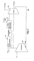
- the power system 100 includes a fuel pre-conditioner 20, which is adapted to convert a fuel to at least one conditioned fuel.
- the "Q" in Figure 1 indicates the addition of energy to the pre-conditioner 20 via combustion/partial oxidation, electrical power, and/or heat.
- the power system 100 further includes a pulse detonation combustor 10, which is adapted to receive the conditioned fuel and a primary oxidizer, to detonate a mixture comprising the conditioned fuel and the primary oxidizer and to exhaust a number of detonation products.
- Exemplary oxidizers include air and compressed air.
- the power system 100 further includes a turbine 30 positioned downstream from the pulse detonation combustor 10 and in flow communication with the pulse detonation combustor 10.
- pulse detonation combustor (or pulse detonation engine) is understood to mean any device or system that produces both a pressure rise and velocity increase from a series of repeating detonations or quasi-detonations within the device.
- a "quasi-detonation” is a supersonic turbulent combustion process that produces a pressure rise and velocity increase higher than the pressure rise and velocity increase produced by a deflagration wave.
- Typical embodiments of pulse detonation combustors include a means of igniting a fuel/oxidizer mixture, for example a fuel/air mixture, and a detonation chamber, in which pressure wave fronts initiated by the ignition process coalesce to produce a detonation wave.
- Each detonation or quasi-detonation is initiated either by external ignition, such as spark discharge or laser pulse, or by gas dynamic processes, such as shock focusing, auto-ignition or by another detonation (cross-fire).
- the geometry of the detonation chamber is such that the pressure rise of the detonation wave expels combustion products out the pulse detonation combustor exhaust to produce a thrust force.
- pulse detonation may be accomplished in a number of types of detonation chambers, including detonation tubes, shock tubes, resonating detonation cavities and annular detonation chambers.
- a primary objective in power system design is increased efficiency, for both simple cycle and combined cycle systems.
- both the pressure ratio and the working temperature must be as high as materials and cooling technology permit.
- high-pressure ratios are achieved using complex high-pressure compressors and turbines, which help to compensate for the four to seven percent (4-7%) pressure loss that results from conventional combustion processes.
- the power system 100 described above achieves pressure rise combustion by performing repeat detonations, in contrast to conventional constant pressure combustion processes. Consequently, high-pressure compressors are not needed to achieve the desired high pressures.
- power system 100 includes a fuel pre-conditioner 20 for converting a fuel to at least one conditioned fuel, that is a more detonable fuel.
- a fuel pre-conditioner 20 for converting a fuel to at least one conditioned fuel, that is a more detonable fuel.
- liquid hydrocarbon fuels may be converted to lighter fuels by fuel pre-conditioner 20.
- Exemplary fuels include hydrocarbon fuels, for example natural gas.
- One of the issues for natural gas is its large cell size.
- preconditioning natural gas for example by reforming (reacting steam and natural gas to produce H2 or a combination of H2 and CO), enhances detonation initiation, thereby facilitating the direct use of natural gas, which is a readily available fuel.
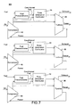
- a number of preconditioning techniques may be employed to convert the fuel to a conditioned fuel, and Figure 2 illustrates several fuel preconditioning techniques.
- the use of air in the pre-conditioner 20 is optional, depending on the specific preconditioning technique being used.
- pyrolysis excludes the use of air.
- the fuel pre-conditioner 20 includes a heat source 22, which is configured to heat the fuel in a vessel 22 so as to pyrolyze the fuel.
- the heat source may be a separate heater.
- the pulse detonation combustor 10 may be used as the heat source 22.
- either direct heating from the pulse detonation combustor 10 may be employed or heat may be supplied by an intermediate fluid that is heated by the pulse detonation combustor 10.
- Another exemplary heat source is an exhaust stream from a turbine 30, which is discussed in greater detail below.
- the fuel pre-conditioner 20 includes both the heat source 22 and a catalyst 26, which is adapted to enhance the pyrolysis of the fuel.
- the particular catalyst employed will vary depending on the type of fuel being pyrolyzed, and exemplary catalysts include a zeolite catalyst or a precious metal, such as platinum.
- the fuel pre-conditioner 20 includes a plasma source 24, which is configured to pyrolyze the fuel in a vessel 28.
- the fuel pre-conditioner 20 comprises a catalyst 26, which is adapted to pyrolyze the fuel in vessel 28. Exemplary catalysts are described above.
- the pulse detonation combustor 10 may be adapted to detonate a mixture consisting of a primary oxidizer and the conditioned fuel from the fuel pre-conditioner 20.
- the mixture may consist of the primary oxidizer, for example compressed air, the conditioned fuel, and a second oxidizer, for example oxygen or an oxygen enriched stream, as discussed below with respect to Figure 10.
- the oxygen reduces the detonation energy of the overall mixture, thereby enhancing the detonation thereof.
- the pulse detonation combustor 10 is further adapted to receive a primary fuel and to detonate a mixture comprising the conditioned fuel, the primary fuel and the primary oxidizer and to exhaust the resulting detonation products.
- Exemplary primary fuels include hydrocabon fuels, such as natural gas, distillate fuels, and gasified solid fuel streams.
- Exemplary solid fuels for solid fuel streams include coal, agricultural products and wood.
- the primary fuel may comprise an even lighter fuel, for example, hydrogen (H 2 ), to enhance detonation of the overall mixture.
- the primary fuel may be heavier than the conditioned fuel supplied by the fuel pre-conditioner 20.
- the conditioned fuel from the fuel pre-conditioner 20 is used to enhance the detonatability of the heavier primary fuel.
- the conditioned fuel could be a CO and H 2 mixture, and the primary fuel could comprise natural gas (CH 4 ).
- a second oxidizer may also be included in the mixture being detonated, to enhance detonation of the conditioned fuel/primary oxidizer/primary fuel mixture.
- the power system 100 further includes a compressor 40 configured to supply air to at least one of the fuel preconditioner 20, the pulse detonation combustor, and the turbine 30.
- the compressor 40 supplies compressed air to the pulse detonation combustor 10, with the primary oxidizer comprising the compressed air.
- the compressor 40 may be powered by the turbine 30, as indicated in Figure 1.
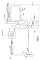
- a combined cycle power system 200 embodiment is described with reference to Figure 3.
- the power system 200 includes the elements of the simple cycle power system 100 described above.
- power system 200 further includes a Rankine bottom cycle (or steam turbine bottoming cycle).
- the steam turbine assembly 110 is adapted to receive an exhaust stream from the turbine 30, to generate steam using the exhaust stream, and to generate power using the steam.
- the steam turbine assembly 110 extracts additional power from waste heat from the simple cycle power system 100.
- the steam turbine assembly 110 includes a steam turbine 60, a condenser 80, and a pump 70.
- the steam turbine 60 is adapted to generate power using the steam.
- the condenser 80 is adapted to receive and condense an exhaust steam from the steam turbine 60 to supply a fluid stream.
- the pump 70 is adapted to receive and pump the fluid stream.
- the steam turbine assembly 110 further includes a heat recovery steam generator 90, which is adapted to receive the exhaust stream from turbine 30, to receive the fluid flow from pump 70, and to generate steam from the fluid flow using the exhaust stream.
- the power plant 300 includes at least one fuel pre-conditioner 20 adapted to convert a fuel to at least one conditioned fuel.
- the power plant further includes a number of power systems 100.
- Each power system 100 includes a pulse detonation combustor 10 and a turbine 30 positioned downstream from the pulse detonation combustor 10, as discussed above with respect to Figure 1.
- a separate fuel pre-conditioner 20 is provided for each of the power systems 100.
- one fuel pre-conditioner 20 may supply the conditioned fuel to two or more power systems 100, as shown for example in Figure 8.
- the power plant 300 further includes at least one compressor 40 configured to supply air to at least one of the fuel pre-conditioner 20, the pulse detonation combustors 10, and the turbines 30.
- a separate compressor 40 is provided for each of the pulse detonation combustors 10.
- one compressor 40 may supply compressed air to two or more pulse detonation combustors 10.
- the exemplary power plant 300 shown in Figure 8 also includes a heat recovery unit 90, which is adapted to use exhaust heat from the turbines 30 to heat an intermediate liquid, such as water, to supply the heated liquid to fuel pre-conditioner 20, for example to supply steam to the fuel pre-conditioner 20.
- a combined cycle power plant 300 embodiment is described with reference to Figure 9.
- the power plant 300 further includes at least one steam turbine assembly 110, which is adapted to receive an exhaust stream from at least one of the turbines 30, to generate steam using the exhaust stream, and to generate power using the steam.
- the use of a single fuel pre-conditioner 20 and multiple compressors 40 in Figure 9 is exemplary. As discussed above with respect to Figures 7 and 8, separate fuel pre-conditioners 20 and/or compressors 40 may be employed for the power systems 100.
- one steam turbine assembly 110 is adapted to receive exhaust streams from a number of turbines 30. Alternatively, several steam turbine assemblies 110 could be employed, depending on the size of the power plant 300.
- the steam turbine assembly 110 includes a steam turbine 60, a condenser 80, a pump 70, and a heat recovery steam generator 90, as discussed in detail above with respect to Figure 3.
- the heat recovery steam generator 90 may be further adapted to supply steam to the fuel pre-conditioner 20, as indicated by a dashed line in Figure 9.
- Figure 11 illustrates a combined cycle power system 600 that includes a reformer 410 that receives steam from the heat recovery steam generator 90.
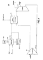
- the power system 400 includes a fuel pre-conditioner 20 comprising a reformer 410, which is adapted to receive and reform a fuel, to generate reformate.
- the "Q" in Figure 4 indicates the addition of energy to the reformer 410 via combustion/partial oxidation, electrical power, and/or heat.
- the power system 400 further includes a pulse detonation combustor 10 adapted to receive the reformate and an oxidizer, to detonate a mixture comprising the reformate and the oxidizer, and to exhaust a number of detonation products.
- the power system 400 further includes a water source 420 adapted to supply the reformer 410 with water and a fuel source 440 adapted to supply reformer 410 with the fuel.
- the reformer 410 is adapted to reform the fuel using the water.
- the power system 400 further includes a pump 422, which is adapted to pump the water from the water source 420 to the reformer 410.
- reformer refers to an apparatus for generating Hydrogen by the reaction of water and a re-formable fuel.
- exemplary re-formable fuels include hydrocarbons, for example natural gas or distillate liquid fuels.
- Exemplary reformers 410 include catalytic reformers 410. In reforming water and hydrocarbon fuel mixtures, such reformers are typically operated in a temperature range of about 800 degrees Fahrenheit (800°F) to about fourteen hundred degrees Fahrenheit (1400°F), depending on the fuel and catalyst. The reformer reacts the water and fuel mixture to generate Hydrogen having quantities of water, methane, carbon dioxide, carbon monoxide and various trace materials entrained (collectively termed "reformate"). Although only one reformer 410 is depicted in Figures 4-6, it should be understood that two or more reformers 410 having like or different catalysts may be employed to more efficiently generate Hydrogen.
- the power system 400 may also include a reformate holding unit 430, which is adapted to receive the reformate from the reformer 410 and to supply the reformate to the pulse detonation combustor 10.
- the reformate may be supplied directly to the pulse detonation combustor 10 from the reformer 410.
- the incorporation of reformate holding unit 430 into power system 400 depends on the capacity and throughput of the reformer 410 and on the fuel consumption rates of the pulse detonation combustor 10.
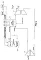
- the pulse detonation combustor 10 is adapted to heat the fuel from the fuel source 440 and the water from the water source 420, so that the fuel and the water received by the reformer 410 are heated.
- warm fuel in Figure 5, it is meant that the fuel is vaporized or heated, and the phrase “warm water” in Figure 5 includes both steam and heated water.
- the fluids are sufficiently hot to promote reforming reactions. This heating may take place in a heat exchanger (not shown in Figure 5).
- the pulse detonation combustor 10 may heat an intermediate fluid (not shown) and indirectly heat the fuel and/or water via the intermediate fluid.
- the water in liquid or steam state
- the pulse detonation combustor directly heats the water and indirectly heats the fuel via the heated water.
- the power system 400 includes a turbine 30 positioned downstream from the pulse detonation combustor 10, as shown, for example, in Figures 4-6.
- the turbine 30 is in flow communication with the pulse detonation combustor 10.
- the power system 400 also includes a heat exchanger adapted to receive an exhaust stream from the turbine 30 to heat the fuel and the water.
- the heat exchanger 450 may also be adapted to heat either the fuel or the water supplied to the reformer.
- the power system 400 may be configured to detonate (1) a mixture comprising the reformate and the oxidizer, (2) a mixture comprising the reformate, a primary fuel (for example, a hydrocarbon fuel, such as natural gas), and the oxidizer, (3) a mixture comprising the reformate, the oxidizer, and a second oxidizer (for example Oxygen or an Oxygen enriched stream), or (4) a mixture comprising the reformate, the oxidizer, a primary fuel, and the second oxidizer.
- a primary fuel for example, a hydrocarbon fuel, such as natural gas
- a second oxidizer for example Oxygen or an Oxygen enriched stream
- the pulse detonation combustor 10 is further adapted to receive a primary fuel (as indicated in Figures 4 and 5 by dashed lines, for example) and to detonate a mixture comprising the primary fuel, the reformate, and the oxidizer and exhaust the detonation products.
- a primary fuel as indicated in Figures 4 and 5 by dashed lines, for example
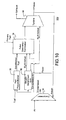
- the power system 500 includes an Oxygen enrichment unit 50 adapted to receive air and to supply an Oxygen enriched stream.
- Exemplary Oxygen contents for the Oxygen enriched stream are in a range of about fifty to about ninety percent (50-90%).
- a pulse detonation combustor 10 is adapted to receive a fuel and the Oxygen enriched stream, to detonate a mixture comprising the fuel and the Oxygen enriched stream, and exhaust a number of detonation products.
- a turbine 30 is positioned downstream from the pulse detonation combustor 10, the turbine being in flow communication with the pulse detonation combustor 10.
- Exemplary Oxygen enrichment units 50 include air separation units or membrane systems. These units are known systems for Oxygen enrichment, and air separation units are conventionally used, for example, in integrated gasification combined cycle coal (IGCC) plants.
- IGCC integrated gasification combined cycle coal
- the Oxygen enrichment unit 50 is further adapted to supply a Nitrogen enriched stream, and the turbine is adapted to receive the Nitrogen enriched stream.
- this Nitrogen enriched stream functions both as a cooling stream to cool the turbine stage parts and to help drive the turbine.
- at least a portion of the Nitrogen enriched stream may be used to cool the pulse detonation combustor 10.
- the power system 500 also includes a fuel pre-conditioner 20 adapted to convert a base fuel to at least one conditioned fuel, such that the fuel received and detonated by the pulse detonation combustor 10 includes the conditioned fuel as indicated in Figure 10.
- the pulse detonation combustor 10 may be further adapted to receive a primary fuel as indicated by a dashed line in Figure 10.
- the fuel received and detonated by the pulse detonation combustor comprises the conditioned fuel and the primary fuel.
- an exemplary fuel pre-conditioner 20 is a reformer 410, which is adapted to receive and reform a base fuel and to generate a reformate.
- the fuel received and detonated by the pulse detonation combustor 10 includes the reformate.
- the power system 500 embodiment of Figure 10 further includes a compressor 40 configured to supply compressed air to at least one of the fuel pre-conditioner 20, pulse detonation combustor 10, and turbine 30.
- the compressor 40 is adapted to supply compressed air to the pulse detonation combustor 10
- the pulse detonation combustor is adapted to detonate a mixture comprising the conditioned fuel, the Oxygen enriched stream, and the compressed air and exhaust a plurality of detonation products.
- the Oxygen enriched stream constitutes only a small percentage of the air mass flow, for example such that about two percent (2%) of the air mass flow is Oxygen.
Landscapes
- Engineering & Computer Science (AREA)
- Chemical & Material Sciences (AREA)
- Combustion & Propulsion (AREA)
- Mechanical Engineering (AREA)
- General Engineering & Computer Science (AREA)
- Engine Equipment That Uses Special Cycles (AREA)
- Fluidized-Bed Combustion And Resonant Combustion (AREA)
Applications Claiming Priority (2)
| Application Number | Priority Date | Filing Date | Title |
|---|---|---|---|
| US10/723,319 US20050109010A1 (en) | 2003-11-25 | 2003-11-25 | Pulse detonation power system and plant with fuel preconditioning |
| US723319 | 2003-11-25 |
Publications (1)
| Publication Number | Publication Date |
|---|---|
| EP1536117A2 true EP1536117A2 (fr) | 2005-06-01 |
Family
ID=34465706
Family Applications (1)
| Application Number | Title | Priority Date | Filing Date |
|---|---|---|---|
| EP04257274A Withdrawn EP1536117A2 (fr) | 2003-11-25 | 2004-11-24 | Moteur à explosion par impulsion et installation avec pré-conditionnement de combustible |
Country Status (5)
| Country | Link |
|---|---|
| US (1) | US20050109010A1 (fr) |
| EP (1) | EP1536117A2 (fr) |
| JP (1) | JP2005155632A (fr) |
| CN (1) | CN1644906A (fr) |
| RU (1) | RU2004134298A (fr) |
Cited By (1)
| Publication number | Priority date | Publication date | Assignee | Title |
|---|---|---|---|---|
| EP2312126A1 (fr) | 2009-10-08 | 2011-04-20 | General Electric Company | Système de génération d'énergie et procédé correspondant de génération d'énergie |
Families Citing this family (13)
| Publication number | Priority date | Publication date | Assignee | Title |
|---|---|---|---|---|
| WO2004072451A1 (fr) * | 2003-02-12 | 2004-08-26 | Ishikawajima-Harima Heavy Industries Co., Ltd. | Systeme de moteur a detonations pulsees pour entrainer une turbine |
| US7690191B2 (en) * | 2006-01-06 | 2010-04-06 | General Electric Company | Fuel preconditioning for detonation combustion |
| US7784265B2 (en) * | 2006-02-07 | 2010-08-31 | General Electric Company | Multiple tube pulse detonation engine turbine apparatus and system |
| DE502007006948D1 (de) * | 2007-09-28 | 2011-05-26 | Max Planck Gesellschaft | Streifenleiter-Antenne und Antennenanordnung für ein Magnetresonanzgerät |
| US7721523B2 (en) * | 2008-04-01 | 2010-05-25 | General Electric Company | Ground based pulse detonation combustor for power generation |
| US20100077726A1 (en) * | 2008-09-30 | 2010-04-01 | General Electric Company | Plenum air preheat for cold startup of liquid-fueled pulse detonation engines |
| US8302377B2 (en) * | 2009-01-30 | 2012-11-06 | General Electric Company | Ground-based simple cycle pulse detonation combustor based hybrid engine for power generation |
| CN101776029B (zh) * | 2010-01-21 | 2012-10-31 | 上海大学 | 燃烧追赶装置 |
| WO2018107335A1 (fr) * | 2016-12-12 | 2018-06-21 | 深圳智慧能源技术有限公司 | Chalumeau pour fournir de l'air de refroidissement à l'aide d'énergie de type source d'air |
| WO2018107334A1 (fr) * | 2016-12-12 | 2018-06-21 | 深圳智慧能源技术有限公司 | Chalumeau au sol d'alimentation en air de combustion par utilisation d'énergie de source d'air |
| US11512260B2 (en) | 2018-06-11 | 2022-11-29 | Donald Gene Taylor | Pulse detonation shockwave gasifier |
| RU2727213C1 (ru) * | 2019-09-02 | 2020-07-21 | Федеральное государственное бюджетное образовательное учреждение высшего образования "Казанский национальный исследовательский технический университет им. А.Н. Туполева-КАИ" (КНИТУ-КАИ) | Силовой привод на базе авиационной газотурбинной установки (АГТУ) |
| CN119878391A (zh) * | 2025-02-27 | 2025-04-25 | 厦门大学 | 一种以水作为冷却剂和推进剂的斜爆震发动机及飞行器 |
Family Cites Families (7)
| Publication number | Priority date | Publication date | Assignee | Title |
|---|---|---|---|---|
| US3615850A (en) * | 1969-03-10 | 1971-10-26 | Gen Electric | System and process employing a reformable fuel to generate electrical energy |
| EP0008166A1 (fr) * | 1978-08-07 | 1980-02-20 | Imperial Chemical Industries Plc | Procédé et appareillage de conversion d'hydrocarbures |
| US6062018A (en) * | 1993-04-14 | 2000-05-16 | Adroit Systems, Inc. | Pulse detonation electrical power generation apparatus with water injection |
| US5345758A (en) * | 1993-04-14 | 1994-09-13 | Adroit Systems, Inc. | Rotary valve multiple combustor pulse detonation engine |
| US5672184A (en) * | 1994-06-24 | 1997-09-30 | Lockheed Corporation | Pulse detonation device for coal gasification |
| US5847353A (en) * | 1995-02-02 | 1998-12-08 | Integrated Environmental Technologies, Llc | Methods and apparatus for low NOx emissions during the production of electricity from waste treatment systems |
| US7150143B2 (en) * | 2003-07-21 | 2006-12-19 | General Electric Company | Hybrid fuel cell-pulse detonation power system |
-
2003
- 2003-11-25 US US10/723,319 patent/US20050109010A1/en not_active Abandoned
-
2004
- 2004-11-24 EP EP04257274A patent/EP1536117A2/fr not_active Withdrawn
- 2004-11-24 RU RU2004134298/06A patent/RU2004134298A/ru not_active Application Discontinuation
- 2004-11-25 CN CN200410100565.3A patent/CN1644906A/zh active Pending
- 2004-11-25 JP JP2004340296A patent/JP2005155632A/ja not_active Withdrawn
Cited By (1)
| Publication number | Priority date | Publication date | Assignee | Title |
|---|---|---|---|---|
| EP2312126A1 (fr) | 2009-10-08 | 2011-04-20 | General Electric Company | Système de génération d'énergie et procédé correspondant de génération d'énergie |
Also Published As
| Publication number | Publication date |
|---|---|
| CN1644906A (zh) | 2005-07-27 |
| US20050109010A1 (en) | 2005-05-26 |
| JP2005155632A (ja) | 2005-06-16 |
| RU2004134298A (ru) | 2006-05-20 |
Similar Documents
| Publication | Publication Date | Title |
|---|---|---|
| EP4001618B1 (fr) | Craquage et séparation de combustible d'ammoniac | |
| US6775987B2 (en) | Low-emission, staged-combustion power generation | |
| EP1536117A2 (fr) | Moteur à explosion par impulsion et installation avec pré-conditionnement de combustible | |
| EP1501139B1 (fr) | Système énergetique hybride comprenant une pile à combustible et un moteur à explosion par impulsion | |
| US6062018A (en) | Pulse detonation electrical power generation apparatus with water injection | |
| AU732503B2 (en) | Method and apparatus for total energy fuel conversion systems | |
| US7367194B2 (en) | Pulse detonation engine system for driving turbine | |
| US5733941A (en) | Hydrocarbon gas conversion system and process for producing a synthetic hydrocarbon liquid | |
| JP2024542934A (ja) | 回転装置で生成された熱エネルギーを使用して水素を生産する方法及び装置 | |
| US20090322102A1 (en) | System and Method for Power Production Using a Hybrid Helical Detonation Device | |
| US3765167A (en) | Power plant process | |
| US8375725B2 (en) | Integrated pressurized steam hydrocarbon reformer and combined cycle process | |
| WO1998035926A1 (fr) | Combustion d'un gaz d'hydrocarbure pour produire un gaz reforme | |
| Ahmed et al. | Simulation Study of a Turbofan Engine With Ammonia As Energy Carrier | |
| US7690191B2 (en) | Fuel preconditioning for detonation combustion | |
| EP3033506B1 (fr) | Procédé et configuration pour l'obtention d'un gaz comprimé | |
| US20240343562A1 (en) | Method and facility for conversion of ammonia and methanol into hydrogen using rotary generated thermal energy | |
| Matveev et al. | Thermal efficiency of a hybrid type plasma reformation system | |
| RU2698781C2 (ru) | Способ получения восстановительного газа | |
| Washcilenko | Plasma Assisted Reforming of Natural Gas for GTL. Part 3. Gas Turbine Integrated GTL | |
| HK1025949B (en) | Method and apparatus for total energy fuel conversion systems | |
| HK1118855A (en) | Method for total energy fuel conversion systems |
Legal Events
| Date | Code | Title | Description |
|---|---|---|---|
| PUAI | Public reference made under article 153(3) epc to a published international application that has entered the european phase |
Free format text: ORIGINAL CODE: 0009012 |
|
| AK | Designated contracting states |
Kind code of ref document: A2 Designated state(s): AT BE BG CH CY CZ DE DK EE ES FI FR GB GR HU IE IS IT LI LU MC NL PL PT RO SE SI SK TR |
|
| AX | Request for extension of the european patent |
Extension state: AL HR LT LV MK YU |
|
| STAA | Information on the status of an ep patent application or granted ep patent |
Free format text: STATUS: THE APPLICATION IS DEEMED TO BE WITHDRAWN |
|
| 18D | Application deemed to be withdrawn |
Effective date: 20090603 |