EP1536151B1 - Sicherungsmutter - Google Patents
Sicherungsmutter Download PDFInfo
- Publication number
- EP1536151B1 EP1536151B1 EP04105900A EP04105900A EP1536151B1 EP 1536151 B1 EP1536151 B1 EP 1536151B1 EP 04105900 A EP04105900 A EP 04105900A EP 04105900 A EP04105900 A EP 04105900A EP 1536151 B1 EP1536151 B1 EP 1536151B1
- Authority
- EP
- European Patent Office
- Prior art keywords
- locking
- locking nut
- nut
- shaft
- screw
- Prior art date
- Legal status (The legal status is an assumption and is not a legal conclusion. Google has not performed a legal analysis and makes no representation as to the accuracy of the status listed.)
- Expired - Lifetime
Links
Images
Classifications
-
- F—MECHANICAL ENGINEERING; LIGHTING; HEATING; WEAPONS; BLASTING
- F16—ENGINEERING ELEMENTS AND UNITS; GENERAL MEASURES FOR PRODUCING AND MAINTAINING EFFECTIVE FUNCTIONING OF MACHINES OR INSTALLATIONS; THERMAL INSULATION IN GENERAL
- F16B—DEVICES FOR FASTENING OR SECURING CONSTRUCTIONAL ELEMENTS OR MACHINE PARTS TOGETHER, e.g. NAILS, BOLTS, CIRCLIPS, CLAMPS, CLIPS OR WEDGES; JOINTS OR JOINTING
- F16B39/00—Locking of screws, bolts or nuts
- F16B39/02—Locking of screws, bolts or nuts in which the locking takes place after screwing down
- F16B39/04—Locking of screws, bolts or nuts in which the locking takes place after screwing down with a member penetrating the screw-threaded surface of at least one part, e.g. a pin, a wedge, cotter-pin, screw
-
- F—MECHANICAL ENGINEERING; LIGHTING; HEATING; WEAPONS; BLASTING
- F16—ENGINEERING ELEMENTS AND UNITS; GENERAL MEASURES FOR PRODUCING AND MAINTAINING EFFECTIVE FUNCTIONING OF MACHINES OR INSTALLATIONS; THERMAL INSULATION IN GENERAL
- F16B—DEVICES FOR FASTENING OR SECURING CONSTRUCTIONAL ELEMENTS OR MACHINE PARTS TOGETHER, e.g. NAILS, BOLTS, CIRCLIPS, CLAMPS, CLIPS OR WEDGES; JOINTS OR JOINTING
- F16B39/00—Locking of screws, bolts or nuts
- F16B39/02—Locking of screws, bolts or nuts in which the locking takes place after screwing down
- F16B39/028—Locking of screws, bolts or nuts in which the locking takes place after screwing down by means of an auxiliary bolt or threaded element whose action provokes the deformation of the main bolt or nut and thereby its blocking
Definitions
- the present invention refers to a locking nut having an internal thread intended to be screwed up on a thread on a shaft and having a locking element, which by means of at least one screw member can be pressed against the thread in the shaft, thereby locking the nut against unintentional unlocking.
- a locking nut of this kind is earlier known from for instance, SE-435 417 C.
- the locking nut according to that patent had a number of internal recesses opening in the inner envelope surface of the nut and each one of which recesses was equipped with a locking element tightened by a screw.
- Each recess is formed with tapering wall portions and the locking elements are formed in correspondence therewith and being elastically deformable, thus that they by the resiliency were intended to move outwards from their locking positions, when the screws were loosened.
- the purpose of the present invention is to provide a locking nut of the type defined in the preamble of the accompanying claim 1, which is designed to give a reliable and safe locking effect and which can be readily un-locked in spite of the fact that it in its locking position can be subjected to very large forces, and this is obtained in that the locking nut according to the present invention has been designed as defined in the characterizing part of the accompanying claim 1.
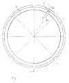
- Fig. 1 is shown in a side view a locking nut 1 according to the invention.
- the locking nut incorporates a ring member 2, which at its outer envelope surface is provided with a number of recesses 3 intended to cooperate with a hook spanner or an impact spanner by which the nut is screwed on the threads in a not shown shaft.
- the bore of the ring member 2 is provided with an internal thread, intimated at 5, and intended to cooperate with a corresponding thread on the not shown shaft.
- a recess 6 which is opening inwardly.
- This inner recess 6 extends along a short length of the envelope surface, in the embodiment shown about 7-8°, and it is limited by straight side walls 6a and a bottom wall 6b perpendicular to the side walls. Radial bores are provided through the ring member 2 thus that they will open into the bottom wall 6b of the inner recess 6. In Fig. 1 only one such bore 7 is visible, but as can be seen in Figs. 2 and 3 there are more bores arranged preferably along a straight axial line.
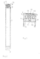
- Fig. 2 shows a section of the locking nut 1 along line II-II in Fig. 1.
- a locking insert 8 positioned in the inner recess 6 and in the embodiment shown two locking screws 9 extending through the bores 7 in the ring member 2, and one release screw 10.
- Fig. 3 shows a portion of the view according to Fig. 2 in bigger scale. From this can be seen the locking insert 8, which has a shape being a complement of the inner recess 6 in the ring member 2.
- the locking insert 8 has an inner edge 8a intended to cooperate with the threads of the not shown shaft for locking the nut on the shaft.
- the locking insert 8 is further provided with a threaded through-bore 11. This threaded through-bore 11 is situated to correspond regarding position and direction with a smooth bore 12 having a shoulder 13, and extending through the ring member 2.
- the release screw 10 is arranged to extend through the bore 12, and to engage with a head against the shoulder 13, and it is arranged to be in threaded engagement with the bore 11 in the locking insert 8.
- the locking nut 1 When the locking nut 1 shall be locked to a shaft it is first positioned around the shaft in a desired position, e.g by being screwed up thereon. At this moment the screw 10 has earlier been positioned in the bore 12 and tightened so much in the threaded bore 11 in the locking insert 8 that the locking insert will be safely kept in its recess 6.
- the release screw 10 When the locking nut thus has reached the desired position, the release screw 10 is loosened and thereupon the set screws 9 in the threaded bores 7 are tightened, whereby their end faces 9a will exert a pressure on the locking insert 8, which thereby will press its edge 8a against the threads on the shaft hereby causing a firm grip between locking nut and shaft. Thereupon the release screw 10 is tightened sufficiently to prevent the locking insert 8 from coming loose due to vibrations during operation of the device in which the shaft is incorporated.
- the release screw 10 is then screwed in further.
- the release screw is not in thread engagement with the smooth part 12 of its bore but in thread engagement against the threads in the bore 11 of the locking insert 8
- tightening of the release screw 10 will subject the locking insert 8 to a "pulling" force, causing the locking insert 8 to be raised from the shaft and thereby to relieve its grip.
Landscapes
- Engineering & Computer Science (AREA)
- General Engineering & Computer Science (AREA)
- Mechanical Engineering (AREA)
- Snaps, Bayonet Connections, Set Pins, And Snap Rings (AREA)
- Turbine Rotor Nozzle Sealing (AREA)
- Mutual Connection Of Rods And Tubes (AREA)
- Transmission Devices (AREA)
- Clamps And Clips (AREA)
Claims (6)
- Sicherungsmutter (1) mit einem Innengewinde (5), das zum Aufschrauben auf ein Gewinde auf einer Welle vorgesehen ist und wenigstens ein Sicherungselement (8) aufweist, das mittels wenigstens einer Sicherungsschraube (9) mit einem Sicherungsteil (8a) von ihm gegen das Gewinde der Welle drückbar ist und dadurch die Mutter gegen unbeabsichtigtes Lösen verriegelt, dadurch gekennzeichnet, daß jedes Sicherungselement (8) mit Freigabemitteln versehen ist, die wenigstens eine Schraube (10) umfassen, die im Gewindeeingriff mit dem Sicherungselement (8) angeordnet ist, um auf das Sicherungselement (8) eine radiale Zugkraft auszuüben, die dafür sorgt, daß sich das Sicherungselement (8) nach dem Lösen der Sicherungsschrauben (9) aus dem Eingriff mit dem Wellengewinde anhebt.
- Sicherungsmutter (1) nach Anspruch 1, dadurch gekennzeichnet, daß das Sicherungselement (8) in einer inneren Ausnehmung (6) in der inneren Hüllfläche der Sicherungsmutter vorgesehen ist und daß die Sicherungsschrauben (9) und die wenigstens eine Löseschraube (10) derart angeordnet sind, daß sie sich durch Radialbohrungen (7, 12) in der Sicherungsmutter (1) erstrecken, die zum Zusammenfallen mit der inneren Ausnehmung (6) der Sicherungsmutter angeordnet sind.
- Sicherungsmutter (1) nach Anspruch 1 oder 2, dadurch gekennzeichnet, daß die Löseschraube (10) derart angeordnet ist, daß sie sich durch eine glattwandige Radialbohrung (12) in der Sicherungsmutter erstreckt und sich im Gewindeingriff mit einer Gewindebohrung (11) befindet, die in dem Sicherungselement vorgesehen ist und in Lage und Ausrichtung mit der glattwandigen Radialbohrung in der Sicherungsmutter (1) zusammenfällt, wobei die glattwandige Radialbohrung (12) in der Sicherungsmutter (1) Mittel (13) zum Begrenzen der Distanz aufweist, um welche die Löseschraube (10) in die Radialbohrung (12) in der Sicherungsmutter einschraubbar ist.
- Sicherungsmutter (1) nach Anspruch 3, dadurch gekennzeichnet, daß die Mittel (13) zum Begrenzen der Distanz, um welche die Löseschraube (10) in die Radialbohrung einschraubbar ist, aus einem Absatz bestehen, der mit einem Kopf der Schraube (10) zusammenwirkt.
- Sicherungsmutter (1) nach einem der vorhergehenden Ansprüche, dadurch gekennzeichnet, daß die Sicherungsschrauben (9) Stellschrauben sind, die im Gewindeeingriff mit Gewindebohrungen (7) in der Sicherungsmutter (1) eingefügt und derart angeordnet sind, daß sie mit ihren radial innenliegenden Stirnflächen (9a) an der Oberfläche des Sicherungselements (8) anliegen, die von dessen Sicherungsteil (8a) abgewandt ist.
- Sicherungsmutter (1) nach einem der vorhergehenden Ansprüche, dadurch gekennzeichnet, daß die äußere Hüllfläche der Sicherungsmutter (1) mit Ausnehmungen (3) versehen ist, die als Schlüsselansätze für ein Werkzeug zum Aufschrauben der Sicherungsmutter auf eine Welle dienen.
Applications Claiming Priority (2)
| Application Number | Priority Date | Filing Date | Title |
|---|---|---|---|
| SE0303191A SE0303191L (sv) | 2003-11-28 | 2003-11-28 | En låsmutter |
| SE0303191 | 2003-11-28 |
Publications (2)
| Publication Number | Publication Date |
|---|---|
| EP1536151A1 EP1536151A1 (de) | 2005-06-01 |
| EP1536151B1 true EP1536151B1 (de) | 2006-09-13 |
Family
ID=29729200
Family Applications (1)
| Application Number | Title | Priority Date | Filing Date |
|---|---|---|---|
| EP04105900A Expired - Lifetime EP1536151B1 (de) | 2003-11-28 | 2004-11-18 | Sicherungsmutter |
Country Status (6)
| Country | Link |
|---|---|
| US (1) | US7179035B2 (de) |
| EP (1) | EP1536151B1 (de) |
| JP (2) | JP2005164035A (de) |
| CN (1) | CN1621702A (de) |
| DE (1) | DE602004002369T2 (de) |
| SE (1) | SE0303191L (de) |
Families Citing this family (5)
| Publication number | Priority date | Publication date | Assignee | Title |
|---|---|---|---|---|
| KR100945807B1 (ko) | 2008-03-28 | 2010-03-08 | (주)씨에프 이엔티 | 나사 체결구조 및 그 나사 조립체 |
| CN102654156B (zh) * | 2012-05-07 | 2014-11-05 | 中国重型机械研究院有限公司 | 一种新型防松紧固件 |
| KR101948977B1 (ko) * | 2016-07-06 | 2019-02-18 | 주식회사 포스코 | 와셔 및 이를 포함한 지그 |
| CN109775384A (zh) * | 2019-01-27 | 2019-05-21 | 湖北天永智能装备有限公司 | 一种酿酒料入窖机器人翻斗浮动定位装置 |
| WO2022222135A1 (en) | 2021-04-23 | 2022-10-27 | Techtronic Cordless Gp | Force amplified fastener for power tool implements |
Family Cites Families (10)
| Publication number | Priority date | Publication date | Assignee | Title |
|---|---|---|---|---|
| US602120A (en) * | 1898-04-12 | Nut-lock | ||
| US189747A (en) * | 1877-04-17 | Improvement in nut-locks | ||
| US1289167A (en) * | 1916-11-28 | 1918-12-31 | John P Hatten | Nut-lock. |
| GB473545A (en) * | 1936-04-09 | 1937-10-11 | William Frederick Forrest Mart | Improvements in or relating to lock nuts |
| US2482214A (en) * | 1945-08-29 | 1949-09-20 | Bell Telephone Labor Inc | Connecting plug |
| US2562143A (en) * | 1948-03-16 | 1951-07-24 | Stanley Works | Router |
| JPS6012791Y2 (ja) * | 1981-07-20 | 1985-04-24 | マエダ工業株式会社 | 自転車のヘツドセツト用袋ナツト |
| SE435417B (sv) | 1983-11-23 | 1984-09-24 | Skf Nova Ab | Mot oavsiktlig vridning lasbar mutter |
| CH676141A5 (de) * | 1988-03-16 | 1990-12-14 | Gewinde Ziegler Ag | |
| SE501072C2 (sv) * | 1993-03-19 | 1994-11-07 | Skf Mekanprodukter Ab | Låsbar precisionsmutter |
-
2003
- 2003-11-28 SE SE0303191A patent/SE0303191L/sv not_active IP Right Cessation
-
2004
- 2004-11-17 JP JP2004332907A patent/JP2005164035A/ja active Pending
- 2004-11-18 DE DE602004002369T patent/DE602004002369T2/de not_active Expired - Lifetime
- 2004-11-18 EP EP04105900A patent/EP1536151B1/de not_active Expired - Lifetime
- 2004-11-24 US US10/995,205 patent/US7179035B2/en not_active Expired - Lifetime
- 2004-11-26 CN CNA2004100973089A patent/CN1621702A/zh active Pending
-
2007
- 2007-12-20 JP JP2007009758U patent/JP3140085U/ja not_active Expired - Lifetime
Also Published As
| Publication number | Publication date |
|---|---|
| JP3140085U (ja) | 2008-03-13 |
| JP2005164035A (ja) | 2005-06-23 |
| SE525149C2 (sv) | 2004-12-07 |
| SE0303191D0 (sv) | 2003-11-28 |
| US7179035B2 (en) | 2007-02-20 |
| US20050117995A1 (en) | 2005-06-02 |
| SE0303191L (sv) | 2004-12-07 |
| CN1621702A (zh) | 2005-06-01 |
| DE602004002369D1 (de) | 2006-10-26 |
| DE602004002369T2 (de) | 2007-09-20 |
| EP1536151A1 (de) | 2005-06-01 |
Similar Documents
| Publication | Publication Date | Title |
|---|---|---|
| EP4094892B1 (de) | Fortschrittliche haltevorrichtung | |
| US20190366761A1 (en) | Wheel Lock With Central Expander | |
| US11274696B2 (en) | Fastening structure | |
| EP1536151B1 (de) | Sicherungsmutter | |
| WO2014116319A1 (en) | Fastener | |
| CN103452995A (zh) | 一种螺母及其安装方法 | |
| US20080240884A1 (en) | Locking device | |
| EP2228176A1 (de) | Diebstahlsicherungsverschlusssystem und Verfahren zu dessen Herstellung | |
| EP3317551B1 (de) | Spannschraube mit drehmomentbegrenzender kappe | |
| EP2816244B1 (de) | Anti-Diebstahl-Verriegelungsvorrichtung für Fahrzeugräder | |
| KR20090032364A (ko) | 과토크 방지 볼트 | |
| US5454674A (en) | Lock nut having locking screw | |
| US3039508A (en) | Wedge locked insert | |
| US1097218A (en) | Lock-nut. | |
| CN203463459U (zh) | 一种螺母 | |
| US20200139760A1 (en) | Wheel lock key assembly and wheel lock key retention mechanism | |
| CN209856195U (zh) | 法兰面螺纹止松双割槽螺母 | |
| EP1331066B1 (de) | Schlüssel eines Befestigungsteils einer diebstahlgesicherten Befestigung eines Fahrzeugrades an einer Radnabe | |
| KR200250795Y1 (ko) | 풀림방지 자리붙은 너트 | |
| CN109281915B (zh) | 一种轴用锁死螺套组件 | |
| CN217381247U (zh) | 一种新型防松动螺栓 | |
| KR200227752Y1 (ko) | 록크너트 체결용 툴 | |
| KR200341702Y1 (ko) | 풀림 방지되는 볼트 | |
| KR200339479Y1 (ko) | 풀림 방지되는 너트 | |
| JP2024539069A (ja) | 高度保持器具 |
Legal Events
| Date | Code | Title | Description |
|---|---|---|---|
| PUAI | Public reference made under article 153(3) epc to a published international application that has entered the european phase |
Free format text: ORIGINAL CODE: 0009012 |
|
| AK | Designated contracting states |
Kind code of ref document: A1 Designated state(s): AT BE BG CH CY CZ DE DK EE ES FI FR GB GR HU IE IS IT LI LU MC NL PL PT RO SE SI SK TR |
|
| AX | Request for extension of the european patent |
Extension state: AL HR LT LV MK YU |
|
| 17P | Request for examination filed |
Effective date: 20051201 |
|
| AKX | Designation fees paid |
Designated state(s): DE FR GB IT |
|
| GRAP | Despatch of communication of intention to grant a patent |
Free format text: ORIGINAL CODE: EPIDOSNIGR1 |
|
| GRAC | Information related to communication of intention to grant a patent modified |
Free format text: ORIGINAL CODE: EPIDOSCIGR1 |
|
| GRAS | Grant fee paid |
Free format text: ORIGINAL CODE: EPIDOSNIGR3 |
|
| GRAA | (expected) grant |
Free format text: ORIGINAL CODE: 0009210 |
|
| AK | Designated contracting states |
Kind code of ref document: B1 Designated state(s): DE FR GB IT |
|
| PG25 | Lapsed in a contracting state [announced via postgrant information from national office to epo] |
Ref country code: IT Free format text: LAPSE BECAUSE OF FAILURE TO SUBMIT A TRANSLATION OF THE DESCRIPTION OR TO PAY THE FEE WITHIN THE PRESCRIBED TIME-LIMIT;WARNING: LAPSES OF ITALIAN PATENTS WITH EFFECTIVE DATE BEFORE 2007 MAY HAVE OCCURRED AT ANY TIME BEFORE 2007. THE CORRECT EFFECTIVE DATE MAY BE DIFFERENT FROM THE ONE RECORDED. Effective date: 20060913 |
|
| REG | Reference to a national code |
Ref country code: GB Ref legal event code: FG4D |
|
| REF | Corresponds to: |
Ref document number: 602004002369 Country of ref document: DE Date of ref document: 20061026 Kind code of ref document: P |
|
| REG | Reference to a national code |
Ref country code: DE Ref legal event code: R096 Ref document number: 602004002369 Country of ref document: DE Effective date: 20061026 |
|
| ET | Fr: translation filed | ||
| PLBE | No opposition filed within time limit |
Free format text: ORIGINAL CODE: 0009261 |
|
| STAA | Information on the status of an ep patent application or granted ep patent |
Free format text: STATUS: NO OPPOSITION FILED WITHIN TIME LIMIT |
|
| 26N | No opposition filed |
Effective date: 20070614 |
|
| REG | Reference to a national code |
Ref country code: DE Ref legal event code: R097 Ref document number: 602004002369 Country of ref document: DE Effective date: 20070614 |
|
| REG | Reference to a national code |
Ref country code: FR Ref legal event code: PLFP Year of fee payment: 12 |
|
| REG | Reference to a national code |
Ref country code: DE Ref legal event code: R082 Ref document number: 602004002369 Country of ref document: DE Representative=s name: PATENTANWAELTE OLBRICHT, BUCHHOLD, KEULERTZ PA, DE |
|
| REG | Reference to a national code |
Ref country code: FR Ref legal event code: PLFP Year of fee payment: 13 |
|
| REG | Reference to a national code |
Ref country code: FR Ref legal event code: PLFP Year of fee payment: 14 |
|
| P01 | Opt-out of the competence of the unified patent court (upc) registered |
Effective date: 20230513 |
|
| PGFP | Annual fee paid to national office [announced via postgrant information from national office to epo] |
Ref country code: GB Payment date: 20231121 Year of fee payment: 20 |
|
| PGFP | Annual fee paid to national office [announced via postgrant information from national office to epo] |
Ref country code: IT Payment date: 20231124 Year of fee payment: 20 Ref country code: FR Payment date: 20231123 Year of fee payment: 20 Ref country code: DE Payment date: 20231127 Year of fee payment: 20 |
|
| REG | Reference to a national code |
Ref country code: DE Ref legal event code: R071 Ref document number: 602004002369 Country of ref document: DE |
|
| REG | Reference to a national code |
Ref country code: GB Ref legal event code: PE20 Expiry date: 20241117 |
|
| PG25 | Lapsed in a contracting state [announced via postgrant information from national office to epo] |
Ref country code: GB Free format text: LAPSE BECAUSE OF EXPIRATION OF PROTECTION Effective date: 20241117 |
|
| PG25 | Lapsed in a contracting state [announced via postgrant information from national office to epo] |
Ref country code: GB Free format text: LAPSE BECAUSE OF EXPIRATION OF PROTECTION Effective date: 20241117 |