EP1536169B1 - Soupape électromagnétique - Google Patents
Soupape électromagnétique Download PDFInfo
- Publication number
- EP1536169B1 EP1536169B1 EP03027541A EP03027541A EP1536169B1 EP 1536169 B1 EP1536169 B1 EP 1536169B1 EP 03027541 A EP03027541 A EP 03027541A EP 03027541 A EP03027541 A EP 03027541A EP 1536169 B1 EP1536169 B1 EP 1536169B1
- Authority
- EP
- European Patent Office
- Prior art keywords
- armature
- valve
- flat spring
- spring
- sleeve
- Prior art date
- Legal status (The legal status is an assumption and is not a legal conclusion. Google has not performed a legal analysis and makes no representation as to the accuracy of the status listed.)
- Expired - Lifetime
Links
Images
Classifications
-
- F—MECHANICAL ENGINEERING; LIGHTING; HEATING; WEAPONS; BLASTING
- F16—ENGINEERING ELEMENTS AND UNITS; GENERAL MEASURES FOR PRODUCING AND MAINTAINING EFFECTIVE FUNCTIONING OF MACHINES OR INSTALLATIONS; THERMAL INSULATION IN GENERAL
- F16K—VALVES; TAPS; COCKS; ACTUATING-FLOATS; DEVICES FOR VENTING OR AERATING
- F16K31/00—Actuating devices; Operating means; Releasing devices
- F16K31/02—Actuating devices; Operating means; Releasing devices electric; magnetic
- F16K31/06—Actuating devices; Operating means; Releasing devices electric; magnetic using a magnet, e.g. diaphragm valves, cutting off by means of a liquid
- F16K31/0644—One-way valve
- F16K31/0655—Lift valves
-
- F—MECHANICAL ENGINEERING; LIGHTING; HEATING; WEAPONS; BLASTING
- F16—ENGINEERING ELEMENTS AND UNITS; GENERAL MEASURES FOR PRODUCING AND MAINTAINING EFFECTIVE FUNCTIONING OF MACHINES OR INSTALLATIONS; THERMAL INSULATION IN GENERAL
- F16K—VALVES; TAPS; COCKS; ACTUATING-FLOATS; DEVICES FOR VENTING OR AERATING
- F16K2200/00—Details of valves
- F16K2200/30—Spring arrangements
- F16K2200/302—Plurality of biasing means, e.g. springs, for opening or closing single valve member
-
- F—MECHANICAL ENGINEERING; LIGHTING; HEATING; WEAPONS; BLASTING
- F16—ENGINEERING ELEMENTS AND UNITS; GENERAL MEASURES FOR PRODUCING AND MAINTAINING EFFECTIVE FUNCTIONING OF MACHINES OR INSTALLATIONS; THERMAL INSULATION IN GENERAL
- F16K—VALVES; TAPS; COCKS; ACTUATING-FLOATS; DEVICES FOR VENTING OR AERATING
- F16K2200/00—Details of valves
- F16K2200/30—Spring arrangements
- F16K2200/304—Adjustable spring pre-loading
-
- F—MECHANICAL ENGINEERING; LIGHTING; HEATING; WEAPONS; BLASTING
- F16—ENGINEERING ELEMENTS AND UNITS; GENERAL MEASURES FOR PRODUCING AND MAINTAINING EFFECTIVE FUNCTIONING OF MACHINES OR INSTALLATIONS; THERMAL INSULATION IN GENERAL
- F16K—VALVES; TAPS; COCKS; ACTUATING-FLOATS; DEVICES FOR VENTING OR AERATING
- F16K2200/00—Details of valves
- F16K2200/30—Spring arrangements
- F16K2200/305—Constructional features of springs
- F16K2200/3051—Generally flat springs
Definitions
- the invention relates to a device for controlling a fluid or gaseous medium of the type specified in the preamble of claim 1.
- a known control device of this type with a 2/2-way valve ( DE 100 39 066 A1 ) has a valve housing with a valve inlet and valve outlet, which communicate with each other via a valve chamber.
- a valve opening enclosing a valve seat is formed, which is governed for flow control of the medium by a valve member which determines by more or less far from the valve seat, the flow through the valve opening flow rate.
- the control of the valve member by means of an electromagnet, which has an anchor sleeve and a seated on the anchor sleeve excitation winding or magnetic coil.
- an anchor plug or counter-anchor is fixedly arranged and an armature displaceably guided, which is rigidly connected via a transfer ram with the valve member.
- the anchor slides with a sliding ring on the inner wall of the anchor sleeve.
- the transfer ram is guided in a slide bearing fixed in the anchor sleeve. This is a precise, low-backlash movement of the anchor be achieved.
- the valve member is pressed in the closed state of the valve by a valve closing spring on the valve seat.
- the valve closing spring is supported, on the one hand, on the armature and, on the other hand, on an adjusting screw screwed into the counter-anchor, by means of which the pretensioning of the valve closing spring can be adjusted.
- the mutually facing ends of the armature and counter-anchor are conical and engage each other, whereby the magnetic force acting between armature and counter-armature is independent of the stroke of the armature.
- the invention has for its object to improve a device for controlling a fluid or gaseous medium of the type mentioned so that an extremely low-friction and precise guidance of the armature in the armature sleeve while maintaining a reliable tightness of the valve is achieved in the closed state.
- the control device has the advantage that through the holder with minimal radial play of the anchor by means of at least two flat springs, the anchor over its entire stroke across the inner wall of the Anchor sleeve touched at any point. At the same time a tight support of the valve member is ensured on the valve seat by the valve closing spring.
- a conical helical compression spring valve closing spring in a introduced into the anchor, central blind hole and is based on the one hand on the blind hole bottom and on the other hand to an adjusting device for setting their Bias off.
- the adjusting device advantageously comprises an adjusting pin which can be screwed into the anchor plug and has a centering pin and a support shoulder surrounding the centering pin for the valve closing spring at its free front end. Due to the conical design of the valve closing spring occurs during armature stroke no friction between the valve closing spring and the hole wall of the blind hole, whereby the low friction of the armature is further increased during the stroke.
- a flat spring engages radially without play on a front end of the armature.
- a flat spring is advantageously inserted in a form-fitting manner in a concentric recess introduced in the end face of the armature and centered on the adjusting pin of the adjusting device.
- the flat spring lies exclusively with its outer edge region on an annular shoulder formed in the recess and is clamped on the annular shoulder by means of a hold-down device inserted into the recess, through which the adjusting pin of the adjusting device is passed.
- the flat spring has a central opening into which the guide pin formed on the alignment pin protrudes positively, wherein the flat spring rests with its surrounding the central opening edge region on the support shoulder on the adjusting pin and is clamped by the valve closing spring.
- the axial bias of the flat spring is varied along with the bias of the closing spring.
- a centering sleeve is pushed onto the guide pin, which engages positively in the central opening of the flat spring and is pressed by the valve closing spring on the support shoulder of the adjusting pin.
- the flat spring lies with its peripheral area surrounding the central opening on the hold-down.
- the axial bias of the flat spring is not changed by adjusting the closing force of the valve closing spring by means of the adjusting pin.
- the flat spring in a valve housing arranged concentrically to the valve seat receptacle positively and is centered on the dipping into the receptacle end side of the armature and preferably clamped between the valve member directly attached to the end face of the armature and the armature ,
- the flat spring only with a central region on an opposite the end face of the armature axially projecting annular shoulder, while the outer edge region of the flat spring rests on a radially projecting in the receiving annular shoulder.
- the flat spring can also be centered with a central opening via a front end of the anchor projecting, conically tapering collar and fixed by the valve member.
- the receptacle is formed by a recess introduced into the valve housing.
- the anchor sleeve immersed with an end portion in the recess and biases the flat spring on the annular shoulder.
- the receptacle is formed by a screwed into the end portion of the anchor sleeve receiving sleeve, wherein the anchor sleeve is in turn immersed with its end portion in a recess formed in the valve housing, but rotatably fixed in the recess.
- the valve member has a seal holder and a seal plate received by the seal holder, which communicates with the valve seat.
- the seal holder is preferably with a Spigot pressed in a central blind hole, which is introduced from the front side of the anchor.
- an adjusting device for adjusting the armature stroke is provided.
- Such adjusting device is realized in a simple manner by a threaded connection between the recess formed in the valve housing and the end portion of the anchor sleeve which dips into the recess. By turning the anchor sleeve this is moved more or less axially, which can vary the distance between the armature and anchor plug.
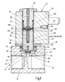
- a 2/2-way valve 11 for controlling a fluid or gaseous medium has a 2/2-way valve 11 and an electromagnet 12 for actuating the 2/2-way valve 11.
- the 2/2-way valve 11 has a valve housing 13 with a valve inlet 14 and a valve outlet 15, which communicate with each other via a valve chamber 16.
- a valve opening 17 is formed, which is enclosed by a valve seat 18 which cooperates for flow control of the medium with a valve member 19 which determines by more or less far from the valve seat 18, the flow through the valve opening 17 flow rate.
- the control of the valve member 19 is effected by means of the electromagnet 12, which preferably has a proportional behavior.
- the electromagnet 12 has an anchor sleeve 20, in which an anchor plug 21 is arranged and an armature stopper 21 axially opposite armature 22 is received axially displaceable.
- Anchor sleeve 20 and anchor plug 21 may be integrally formed with each other.
- the anchor sleeve 20 is surrounded by a field winding or magnetic coil 23 which is fixed axially immovably to the anchor sleeve 20.
- the mutually facing ends of armature 22 and anchor plug 21 are conical and interlock, whereby the force acting between armature 22 and anchor plug 21 magnetic force is independent of the stroke of the armature 22.
- the anchor sleeve 20 is immersed with an end portion 201 in an inserted in the valve housing 13, diameter-graded recess 24, the diameter smaller, the lower valve chamber 16 forms.
- the end portion 201 is located in the larger diameter, upper portion of the recess 24 and is supported on an annular shoulder 241 formed by the diameter gradation in the recess 24.
- the end portion 201 of the anchor sleeve 20 is sealed relative to the recess 24 by means of a sealing ring 25.
- the anchor sleeve 20 is secured to the valve housing 13 by means of a pushed over the anchor sleeve 20 mounting ring 26 which engages over the sealing ring 25 radially and this presses against an end portion 201 formed on the outer annular shoulder.
- the fastening ring 26 is od on the valve body 13, for example by welding, screwing. Like., Set.
- the armature 22 is held by means of two flat springs 27, 28 in the anchor sleeve 20 so that it rests with minimal radial play without contact in the anchor sleeve 20 and is axially displaceable, without touching the inner wall of the anchor sleeve 20.
- the one flat spring 27 is arranged at the upper front end and the other flat spring 28 at the lower end face of the armature 22.
- the valve member 19 is attached.
- the valve member 19 has a seal holder 30 with a pin 301 integrally formed thereon and a sealing plate 31 received in the seal holder 30, which cooperates with the valve seat 18.
- the seal holder 30 is pressed with its pin 301 into a blind hole 32 made in the end face of the armature 22.
- concentric collar 33 is formed, which is designed as a truncated cone, which tapers towards the free end. Between the collar 33 and the seal holder 30 which is a flat spring 28 is clamped.
- valve closing spring 29 The tightness between the sealing plate 31 and the valve seat 18 in the closed state of the valve 11 is brought about by a valve closing spring 29.
- the valve closing spring 29 is inserted into a blind hole 35, which is introduced from the anchor plug 21 facing the front end of the armature 22 in the armature 22. Trained as a helical compression spring valve closing spring 29 is supported on the one hand on the bottom of the blind hole 35 and on the other hand on an adjusting pin 36 of an adjusting device for adjusting the biasing force of the valve closing spring 29.
- an axially projecting guide pin 361 is formed, which is annularly surrounded by a radial support shoulder 362.
- a centering sleeve 37 is pushed, which rests with a flange 371 on the support shoulder 362.
- the adjusting pin 36 facing the end of the valve closing spring 29 is guided on the centering sleeve 37 and is supported on the flange 371, this pressing against the support shoulder 362 from.
- the adjusting pin 36 is screwed in the anchor plug 21, so that by turning the adjusting pin 36, the valve closing spring 29 more or less can be compressed.
- the adjusting pin 36 passes with its protruding from the stopper 21, the free end through a hold-down 38, which dips into a introduced in the end face of the armature 22, concentric recess 39 and rests there on an opening 39 formed in the annular shoulder 391.
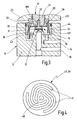
- the upper and lower flat spring 27, 28 are formed identically with different diameters.
- An embodiment of the flat springs 27, 28 is in Fig. 4 shown in plan view.
- Each flat spring 27, 28 is for example made of spring steel with a thickness of 0.05 - 0.3 mm and provided with a central opening 40.
- 27 or 28 spirally extending recesses 41 are incorporated with different radial spacing in the flat spring.
- the flat spring 27 has a smaller diameter than the flat spring 28 and is positively inserted into the recess 39 in the armature 22, so that they can perform no radial relative movement to the armature 22. Its outer edge region rests on the annular shoulder 391 formed in the recess 39 and is clamped by the hold-down device 38.
- the flange 371 of the centering sleeve 37 concentrates the flat spring 27 on the adjusting pin 36.
- the larger diameter, lower flat spring 28 is positively inserted into the recess 24 in the valve housing 13 and lies with its outer edge region on the annular shoulder 241 of the recess 24 and is tightened by the anchor sleeve 20 on the annular shoulder 241.
- the flat spring 28 is placed with its central opening 40 on the conical flange 33 and secured by the seal holder 30 against removal, so that the flat spring 28 is centered on the lateral surface of the collar 33.
- the peripheral region of the flat spring 28 surrounding the central opening 40 can rest on the annular end face of the collar 33, and the pin 301 of the seal holder 30 can pass through the central opening 40 in a form-fitting manner so that the flat spring 28 is centered on the pin 301 of the seal holder 30 and on the other hand is clamped between the armature 22 and the seal holder 30.
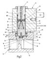
- the control device is modified insofar as that introduced into the armature 22 blind hole 35 for receiving the valve closing spring 29 is designed with a much larger diameter and at the same time forms the recess 39 for receiving the upper flat spring 27 and the hold-38.
- the blind hole 35 tapers at least in the region of the recess 39 in the direction of the hole bottom.
- the hold-down device 38 and the flat spring 27, which is supported by its outer edge region on an annular collar on the underside of the hold-down 38 form fit.
- the flat spring 27 abuts with its central edge 40 enclosing, inner edge region of the support shoulder 362 of the adjusting pin 36 and is centered by the guide pin 361 of the adjusting pin 36.
- the valve closing spring 39 is designed as a conical spring which widens downwards and is supported by the upper flat spring 27 on the support shoulder 362 on the adjusting pin 36.
- the adjusting device for adjusting the bias of the valve closing spring 29 also acts on the upper flat spring 27 and changes the axial biasing force with.
- the conical shape of the valve closing spring 29 friction between the valve closing spring 29 and the hole wall of the blind hole 35 is avoided.
- an adjusting device for adjusting the armature stroke This consists in the simplest case of a screw thread 42 between the present in the valve housing 13 recess 24 and the end portion 201 of the anchor sleeve 20.
- the anchor sleeve 20 can move axially by turning in the recess 24, so that the distance between the anchor plug 21 on the one hand and the Anchor 22 and the preferably made of non-magnetic material hold-down 38 on the other hand, and thus the stroke of the armature 22 can be changed.
- the control device is modified insofar as additionally an adjusting device for adjusting the axial preload of the lower flat spring 28 is provided.
- the anchor sleeve 20 is in turn tightly inserted with its end portion 201 in the present in the valve housing 13 recess 24, but is rotatably disposed in the recess 24 about its sleeve axis.
- a receiving sleeve 43 by means of a thread 44 can be screwed.
- a radial annular shoulder 431 is formed, on which the lower flat spring 28 rests with its outer edge region.
- the flat spring 28 is centered here via its central opening 40 by means of the journal 301 of the seal holder 30 on the armature 22 and clamped with its central opening 40 enclosing the edge region between the seal holder 30 and the annular end face of the collar 33 at anchor 22. If the anchor sleeve 20 is now rotated so that the receiving sleeve 43, which is held non-rotatably in the recess 39, screwed down through the thread 44, the outer edge of the lower flat spring 28 by the annular shoulder 431 on the receiving sleeve 43 down pressed, so that the axial biasing force of the lower flat spring 28 increases.
- a suitably directed bias of the flat springs 27, 28 can be used to support the opening stroke or to increase the sealing force of the valve member 19.
Landscapes
- Engineering & Computer Science (AREA)
- General Engineering & Computer Science (AREA)
- Mechanical Engineering (AREA)
- Magnetically Actuated Valves (AREA)
Claims (9)
- Dispositif de régulation d'un milieu fluide ou gazeux, comprenant un boîtier de soupape (13) qui présente une entrée et une sortie de soupape (14, 15), qui sont en liaison l'une avec l'autre par le biais d'une ouverture de soupape (17) entourée par un siège de soupape (18), comprenant un organe de soupape (19) coopérant avec le siège de soupape (18) pour la régulation du débit du milieu à travers l'ouverture de soupape (17), et comprenant un électroaimant (12) qui présente une armature (22) connectée à l'organe de soupape (19), une gaine d'armature (20) recevant l'armature (22) et un bouchon d'armature (21), et une bobine magnétique (23) entourant la gaine d'armature (20), l'armature (22) étant maintenue par le biais d'au moins deux ressorts de telle sorte qu'elle s'insère de manière déplaçable axialement sans contact dans la gaine d'armature (20) et un ressort servant à positionner l'organe de soupape (19) sur le siège de soupape (18),
caractérisé en ce qu'
un ressort de fermeture de soupape précontraint (29) vient en prise au niveau de l'armature (22) pour positionner l'organe de soupape (19) sur le siège de soupape (18), en ce que sur l'armature (22) s'engagent au moins deux ressorts plats (27, 28), dont au moins un (27) est disposé à une extrémité frontale et au moins un autre ressort plat (28) est disposé à l'autre extrémité frontale de l'armature (22), et en ce que chaque ressort plat (27, 28) est associé à un dispositif d'ajustement pour ajuster la précontrainte axiale du ressort. - Dispositif selon la revendication 1, caractérisé en ce que le ressort de fermeture de soupape (29) s'insère dans un trou borgne central (35) pratiqué dans l'armature (22), et s'appuie d'une part contre le fond du trou borgne et d'autre part contre un épaulement d'appui (362), qui est réalisé sur une broche d'ajustage (36) d'un dispositif d'ajustage, pouvant être vissée dans le bouchon d'armature (21), pour l'ajustement de la force de précontrainte du ressort de fermeture de soupape (29), et en ce qu'un tourillon de guidage (361) saillant depuis la broche d'ajustage (36), entouré par l'épaulement d'appui (362), plonge dans le ressort de fermeture de soupape (29) réalisé de préférence sous forme de ressort à boudin de pression s'élargissant vers le fond du trou borgne.
- Dispositif selon l'une quelconque des revendications 1 ou 2, caractérisé en ce qu'au moins un ressort plat (27) s'insère par engagement par coopération de forme dans un évidement (39) concentrique pratiqué dans un côté frontal de l'armature (22) tourné vers le bouchon d'armature (21), et est centré sur la broche d'ajustage (36).
- Dispositif selon l'une quelconque des revendications 1 à 3, caractérisé en ce qu'au moins un ressort plat (27) s'applique du côté du bord sur un épaulement annulaire (391) réalisé dans l'évidement (39) et est serré fermement sur l'épaulement annulaire (391) au moyen d'un serre-flan (38) inséré dans l'évidement (39), à travers lequel la broche d'ajustage (36) est guidée.
- Dispositif selon l'une quelconque des revendications 1 à 4, caractérisé en ce qu'au moins un ressort plat (27) présente une ouverture centrale (40) qui est traversée avec engagement par coopération de forme par le tourillon de guidage (361) de la broche d'ajustage (36) ou par une gaine de centrage (37) poussée sur le tourillon de guidage (361), et en ce que le ressort plat (27) s'applique avec sa région de bord entourant l'ouverture centrale (40) sur l'épaulement d'appui (362) de la broche d'ajustage (36) et/ou sur le serre-flan (38).
- Dispositif selon l'une quelconque des revendications 1 à 5, caractérisé en ce qu'au moins un ressort plat (28) s'insère par engagement par coopération de forme dans un logement disposé concentriquement au siège de soupape (18) dans le boîtier de soupape (13) et est centré sur le côté frontal de l'armature (22) plongeant dans le logement, et est de préférence serré entre l'organe de soupape (19) fixé à l'armature (22) et l'armature (22).
- Dispositif selon la revendication 6, caractérisé en ce qu'il est réalisé dans le logement un épaulement annulaire (241 ; 431) saillant radialement, sur lequel s'applique le ressort plat (28) avec sa région de bord extérieure.
- Dispositif selon la revendication 7, caractérisé en ce que le logement est formé par un évidement (24) pratiqué dans le boîtier de soupape (13), et en ce que le ressort plat (28) est serré fermement sur l'épaulement annulaire (241) au moyen de la gaine d'armature (20) plongeant avec une portion d'extrémité (201) dans l'évidement (24).
- Dispositif selon la revendication 7, caractérisé en ce que la gaine d'armature (20) plonge avec une portion d'extrémité (201) de manière rotative dans un évidement (24) réalisé dans le boîtier de soupape (13), et en ce que le logement avec l'épaulement annulaire (431) est formé par une gaine de logement (43) pouvant être vissée dans la portion d'extrémité (201) de la gaine d'armature (20) et maintenue de manière non rotative dans le boîtier de soupape (13).
Priority Applications (2)
| Application Number | Priority Date | Filing Date | Title |
|---|---|---|---|
| EP03027541A EP1536169B1 (fr) | 2003-11-29 | 2003-11-29 | Soupape électromagnétique |
| DE50310748T DE50310748D1 (de) | 2003-11-29 | 2003-11-29 | Elektromagnetisches Ventil |
Applications Claiming Priority (1)
| Application Number | Priority Date | Filing Date | Title |
|---|---|---|---|
| EP03027541A EP1536169B1 (fr) | 2003-11-29 | 2003-11-29 | Soupape électromagnétique |
Publications (2)
| Publication Number | Publication Date |
|---|---|
| EP1536169A1 EP1536169A1 (fr) | 2005-06-01 |
| EP1536169B1 true EP1536169B1 (fr) | 2008-11-05 |
Family
ID=34442917
Family Applications (1)
| Application Number | Title | Priority Date | Filing Date |
|---|---|---|---|
| EP03027541A Expired - Lifetime EP1536169B1 (fr) | 2003-11-29 | 2003-11-29 | Soupape électromagnétique |
Country Status (2)
| Country | Link |
|---|---|
| EP (1) | EP1536169B1 (fr) |
| DE (1) | DE50310748D1 (fr) |
Cited By (19)
| Publication number | Priority date | Publication date | Assignee | Title |
|---|---|---|---|---|
| CN102996792A (zh) * | 2012-12-24 | 2013-03-27 | 北京七星华创电子股份有限公司 | 一种金属密封圈 |
| EP2682655A2 (fr) | 2012-07-05 | 2014-01-08 | Asco Joucomatic SA | Electrovanne du type à noyau plat et ressort plat |
| US8839815B2 (en) | 2011-12-15 | 2014-09-23 | Honeywell International Inc. | Gas valve with electronic cycle counter |
| US8899264B2 (en) | 2011-12-15 | 2014-12-02 | Honeywell International Inc. | Gas valve with electronic proof of closure system |
| US8905063B2 (en) | 2011-12-15 | 2014-12-09 | Honeywell International Inc. | Gas valve with fuel rate monitor |
| US8947242B2 (en) | 2011-12-15 | 2015-02-03 | Honeywell International Inc. | Gas valve with valve leakage test |
| EP2853792A1 (fr) | 2013-09-26 | 2015-04-01 | Asco Numatics GmbH | Dispositif destiné à la régulation du débit d'un fluide |
| US9074770B2 (en) | 2011-12-15 | 2015-07-07 | Honeywell International Inc. | Gas valve with electronic valve proving system |
| CN105179540A (zh) * | 2015-08-25 | 2015-12-23 | 同济大学 | 扇形弹簧臂及其组成的片弹簧和采用该片弹簧的压缩机 |
| US9234661B2 (en) | 2012-09-15 | 2016-01-12 | Honeywell International Inc. | Burner control system |
| US9557059B2 (en) | 2011-12-15 | 2017-01-31 | Honeywell International Inc | Gas valve with communication link |
| US9995486B2 (en) | 2011-12-15 | 2018-06-12 | Honeywell International Inc. | Gas valve with high/low gas pressure detection |
| US10024439B2 (en) | 2013-12-16 | 2018-07-17 | Honeywell International Inc. | Valve over-travel mechanism |
| US10203049B2 (en) | 2014-09-17 | 2019-02-12 | Honeywell International Inc. | Gas valve with electronic health monitoring |
| US10215291B2 (en) | 2013-10-29 | 2019-02-26 | Honeywell International Inc. | Regulating device |
| US10564062B2 (en) | 2016-10-19 | 2020-02-18 | Honeywell International Inc. | Human-machine interface for gas valve |
| US10697815B2 (en) | 2018-06-09 | 2020-06-30 | Honeywell International Inc. | System and methods for mitigating condensation in a sensor module |
| US10851993B2 (en) | 2011-12-15 | 2020-12-01 | Honeywell International Inc. | Gas valve with overpressure diagnostics |
| US11073281B2 (en) | 2017-12-29 | 2021-07-27 | Honeywell International Inc. | Closed-loop programming and control of a combustion appliance |
Families Citing this family (25)
| Publication number | Priority date | Publication date | Assignee | Title |
|---|---|---|---|---|
| DE502007003929D1 (de) * | 2007-03-14 | 2010-07-08 | Asco Joucomatic Gmbh | Vorrichtung zur Regelung eines fluiden oder gasförmigen Mediums |
| DE102007047422B4 (de) | 2007-10-04 | 2024-06-20 | Robert Bosch Gmbh | Elektromagnetisches Druckventil |
| SE531814C2 (sv) * | 2007-10-17 | 2009-08-11 | Oehlins Racing Ab | Ventil med fjäderarrangemang för justering av en stötdämpares dämpmedieflöde |
| DE502007004672D1 (de) | 2007-12-08 | 2010-09-16 | Asco Joucomatic Gmbh | Vorrichtung zur Durchflussregelung eines flüssigen oder gasförmigen Mediums |
| DE102009022538A1 (de) | 2009-05-25 | 2010-12-02 | Svm Schultz Verwaltungs-Gmbh & Co. Kg | Elektromagnet mit einem mediengefüllten Ankerraum |
| FR2955908B1 (fr) | 2010-02-02 | 2012-05-04 | Asco Joucomatic Sa | Electrovanne pilote |
| DE102010002224A1 (de) * | 2010-02-23 | 2011-08-25 | Robert Bosch GmbH, 70469 | Magnetventil zum Steuern eines Fluids |
| EP2365239B1 (fr) | 2010-03-12 | 2015-03-04 | Asco Numatics GmbH | Dispositif destiné à la régulation du débit d'un milieu liquide ou gazeux |
| DE102010030299A1 (de) * | 2010-06-21 | 2011-12-22 | Krones Aktiengesellschaft | Vorrichtung zum Antreiben eines Doppelsitzventils |
| EP2400193B1 (fr) * | 2010-06-23 | 2019-08-28 | Asco Numatics GmbH | Dispositif destiné à la régulation du débit d'un milieu liquide ou gazeux |
| DE202010010279U1 (de) | 2010-07-15 | 2010-11-18 | Bürkert Werke GmbH | Magnetventil |
| EP2600360B1 (fr) * | 2011-12-01 | 2017-04-12 | SVM Schultz Verwaltungs-GmbH & Co. KG | Electroaimant |
| US9835265B2 (en) | 2011-12-15 | 2017-12-05 | Honeywell International Inc. | Valve with actuator diagnostics |
| US9846440B2 (en) | 2011-12-15 | 2017-12-19 | Honeywell International Inc. | Valve controller configured to estimate fuel comsumption |
| CN103185167B (zh) * | 2011-12-30 | 2016-03-02 | 北京谊安医疗系统股份有限公司 | 板式弹簧组件 |
| CN103629415B (zh) * | 2012-08-23 | 2016-03-02 | 丹佛斯(天津)有限公司 | 动铁芯组件及使用其的电磁阀 |
| US10422531B2 (en) | 2012-09-15 | 2019-09-24 | Honeywell International Inc. | System and approach for controlling a combustion chamber |
| US9841122B2 (en) | 2014-09-09 | 2017-12-12 | Honeywell International Inc. | Gas valve with electronic valve proving system |
| US10088068B2 (en) * | 2015-09-23 | 2018-10-02 | Hamilton Sundstrand Corporation | Flexures for flow regulation devices |
| US10503181B2 (en) | 2016-01-13 | 2019-12-10 | Honeywell International Inc. | Pressure regulator |
| JP6416159B2 (ja) * | 2016-07-25 | 2018-10-31 | Ckd株式会社 | 電磁アクチュエータ |
| JP6909077B2 (ja) * | 2017-07-05 | 2021-07-28 | 日立Astemo株式会社 | 緩衝器 |
| CN111692398B (zh) * | 2020-05-19 | 2021-05-07 | 徐州华宝能源科技有限公司 | 一种天然气站开关安全保护装置 |
| CN114763855B (zh) * | 2021-01-13 | 2025-08-19 | 浙江三花智能控制股份有限公司 | 一种比例调节装置及具有该比例调节装置的燃气阀 |
| CN114623243B (zh) * | 2022-03-15 | 2024-06-04 | 一汽解放汽车有限公司 | 用于燃料电池的喷射阀 |
Family Cites Families (4)
| Publication number | Priority date | Publication date | Assignee | Title |
|---|---|---|---|---|
| GB2189010B (en) * | 1986-03-07 | 1990-03-21 | Alexander Controls Ltd | Apparatus for controlling the flow of gas |
| EP1232081B1 (fr) * | 1999-11-16 | 2004-02-11 | Continental Teves AG & Co. oHG | Vanne electromagnetique |
| DE10039066A1 (de) | 2000-08-10 | 2002-02-21 | Asco Joucomatic Gmbh & Co | Ventil zur Regelung eines fluiden oder gasförmigen Mediums |
| JP2002295711A (ja) * | 2001-04-02 | 2002-10-09 | Aisan Ind Co Ltd | 高圧開閉弁装置 |
-
2003
- 2003-11-29 DE DE50310748T patent/DE50310748D1/de not_active Expired - Lifetime
- 2003-11-29 EP EP03027541A patent/EP1536169B1/fr not_active Expired - Lifetime
Cited By (21)
| Publication number | Priority date | Publication date | Assignee | Title |
|---|---|---|---|---|
| US9557059B2 (en) | 2011-12-15 | 2017-01-31 | Honeywell International Inc | Gas valve with communication link |
| US8839815B2 (en) | 2011-12-15 | 2014-09-23 | Honeywell International Inc. | Gas valve with electronic cycle counter |
| US8899264B2 (en) | 2011-12-15 | 2014-12-02 | Honeywell International Inc. | Gas valve with electronic proof of closure system |
| US8905063B2 (en) | 2011-12-15 | 2014-12-09 | Honeywell International Inc. | Gas valve with fuel rate monitor |
| US8947242B2 (en) | 2011-12-15 | 2015-02-03 | Honeywell International Inc. | Gas valve with valve leakage test |
| US10851993B2 (en) | 2011-12-15 | 2020-12-01 | Honeywell International Inc. | Gas valve with overpressure diagnostics |
| US9074770B2 (en) | 2011-12-15 | 2015-07-07 | Honeywell International Inc. | Gas valve with electronic valve proving system |
| US10697632B2 (en) | 2011-12-15 | 2020-06-30 | Honeywell International Inc. | Gas valve with communication link |
| US9995486B2 (en) | 2011-12-15 | 2018-06-12 | Honeywell International Inc. | Gas valve with high/low gas pressure detection |
| EP2682655A2 (fr) | 2012-07-05 | 2014-01-08 | Asco Joucomatic SA | Electrovanne du type à noyau plat et ressort plat |
| US9234661B2 (en) | 2012-09-15 | 2016-01-12 | Honeywell International Inc. | Burner control system |
| CN102996792A (zh) * | 2012-12-24 | 2013-03-27 | 北京七星华创电子股份有限公司 | 一种金属密封圈 |
| CN102996792B (zh) * | 2012-12-24 | 2015-11-25 | 北京七星华创电子股份有限公司 | 一种金属密封圈 |
| EP2853792A1 (fr) | 2013-09-26 | 2015-04-01 | Asco Numatics GmbH | Dispositif destiné à la régulation du débit d'un fluide |
| US10215291B2 (en) | 2013-10-29 | 2019-02-26 | Honeywell International Inc. | Regulating device |
| US10024439B2 (en) | 2013-12-16 | 2018-07-17 | Honeywell International Inc. | Valve over-travel mechanism |
| US10203049B2 (en) | 2014-09-17 | 2019-02-12 | Honeywell International Inc. | Gas valve with electronic health monitoring |
| CN105179540A (zh) * | 2015-08-25 | 2015-12-23 | 同济大学 | 扇形弹簧臂及其组成的片弹簧和采用该片弹簧的压缩机 |
| US10564062B2 (en) | 2016-10-19 | 2020-02-18 | Honeywell International Inc. | Human-machine interface for gas valve |
| US11073281B2 (en) | 2017-12-29 | 2021-07-27 | Honeywell International Inc. | Closed-loop programming and control of a combustion appliance |
| US10697815B2 (en) | 2018-06-09 | 2020-06-30 | Honeywell International Inc. | System and methods for mitigating condensation in a sensor module |
Also Published As
| Publication number | Publication date |
|---|---|
| DE50310748D1 (de) | 2008-12-18 |
| EP1536169A1 (fr) | 2005-06-01 |
Similar Documents
| Publication | Publication Date | Title |
|---|---|---|
| EP1536169B1 (fr) | Soupape électromagnétique | |
| EP2400193B1 (fr) | Dispositif destiné à la régulation du débit d'un milieu liquide ou gazeux | |
| DE3802648C2 (fr) | ||
| EP0615498B1 (fr) | Soupape magnetique | |
| DE69103563T2 (de) | Elektromagnetisch betätigte Kraftstoffeinspritzvorrichtung für eine Brennkraftmaschine. | |
| DE2843514C2 (fr) | ||
| DE3107775C2 (fr) | ||
| EP2246601B1 (fr) | Soupape hydraulique électromagnétique | |
| EP2906815B1 (fr) | Soupape pour une pompe | |
| DE102018105348B4 (de) | Magnetventil | |
| EP1970610A1 (fr) | Dispositif destiné à la régulation d'un fluide liquide ou gazeux | |
| DE3335169C2 (de) | Kraftstoffeinspritzvorrichtung | |
| EP2156046A1 (fr) | Ajustement de trajet d'armature pour électrovanne | |
| EP2558757A1 (fr) | Régulateur de débit | |
| DE4423103A1 (de) | Elektromagnetisch beetätigbares Ventil | |
| DE4428385B4 (de) | Ventilkörper | |
| EP2853792B2 (fr) | Dispositif destiné à la régulation du débit d'un fluide | |
| DE69124977T2 (de) | Durchflussregler | |
| DE1143108B (de) | Hydraulik-Stossdaempfer fuer Steuerregler von Fluessigkeitsverteilern zum Aufrechterhalten der Hoehenlage eines Fahrzeugaufbaues oder -rahmens | |
| DE2657197C2 (fr) | ||
| DE1961248A1 (de) | Ventil | |
| DE19625349A1 (de) | Magnetbetätigtes Sitzventil | |
| DE19852409A1 (de) | Druckbegrenzungsventil, insbesondere für Fahrzeuge | |
| DE4022395C2 (de) | Proportionalmagnetventil und Verfahren zur Montage eines solchen Proportionalmagnetventiles | |
| DE3016543A1 (de) | Kraftstoffeinspritzanlage |
Legal Events
| Date | Code | Title | Description |
|---|---|---|---|
| PUAI | Public reference made under article 153(3) epc to a published international application that has entered the european phase |
Free format text: ORIGINAL CODE: 0009012 |
|
| AK | Designated contracting states |
Kind code of ref document: A1 Designated state(s): AT BE BG CH CY CZ DE DK EE ES FI FR GB GR HU IE IT LI LU MC NL PT RO SE SI SK TR |
|
| AX | Request for extension of the european patent |
Extension state: AL LT LV MK |
|
| 17P | Request for examination filed |
Effective date: 20051005 |
|
| TPAC | Observations filed by third parties |
Free format text: ORIGINAL CODE: EPIDOSNTIPA |
|
| AKX | Designation fees paid |
Designated state(s): CH DE FR GB LI |
|
| GRAP | Despatch of communication of intention to grant a patent |
Free format text: ORIGINAL CODE: EPIDOSNIGR1 |
|
| GRAS | Grant fee paid |
Free format text: ORIGINAL CODE: EPIDOSNIGR3 |
|
| GRAA | (expected) grant |
Free format text: ORIGINAL CODE: 0009210 |
|
| AK | Designated contracting states |
Kind code of ref document: B1 Designated state(s): CH DE FR GB LI |
|
| REG | Reference to a national code |
Ref country code: GB Ref legal event code: FG4D Free format text: NOT ENGLISH |
|
| REG | Reference to a national code |
Ref country code: CH Ref legal event code: EP |
|
| REG | Reference to a national code |
Ref country code: CH Ref legal event code: NV Representative=s name: PATENTANWALTSBUERO JEAN HUNZIKER AG |
|
| REF | Corresponds to: |
Ref document number: 50310748 Country of ref document: DE Date of ref document: 20081218 Kind code of ref document: P |
|
| PLBE | No opposition filed within time limit |
Free format text: ORIGINAL CODE: 0009261 |
|
| STAA | Information on the status of an ep patent application or granted ep patent |
Free format text: STATUS: NO OPPOSITION FILED WITHIN TIME LIMIT |
|
| 26N | No opposition filed |
Effective date: 20090806 |
|
| REG | Reference to a national code |
Ref country code: DE Ref legal event code: R082 Ref document number: 50310748 Country of ref document: DE Representative=s name: KRATZSCH UND KOLLEGEN, DE |
|
| REG | Reference to a national code |
Ref country code: DE Ref legal event code: R082 Ref document number: 50310748 Country of ref document: DE Representative=s name: WITTE, WELLER & PARTNER, DE Effective date: 20110822 Ref country code: DE Ref legal event code: R081 Ref document number: 50310748 Country of ref document: DE Owner name: ASCO NUMATICS GMBH, DE Free format text: FORMER OWNER: ASCO JOUCOMATIC GMBH, 75248 OELBRONN-DUERRN, DE Effective date: 20110822 Ref country code: DE Ref legal event code: R082 Ref document number: 50310748 Country of ref document: DE Representative=s name: WITTE, WELLER & PARTNER PATENTANWAELTE MBB, DE Effective date: 20110822 |
|
| REG | Reference to a national code |
Ref country code: DE Ref legal event code: R082 Ref document number: 50310748 Country of ref document: DE Representative=s name: WITTE, WELLER & PARTNER, DE Ref country code: DE Ref legal event code: R082 Ref document number: 50310748 Country of ref document: DE Representative=s name: WITTE, WELLER & PARTNER PATENTANWAELTE MBB, DE |
|
| REG | Reference to a national code |
Ref country code: CH Ref legal event code: PUE Owner name: ASCO NUMATICS GMBH, DE Free format text: FORMER OWNER: ASCO JOUCOMATIC GMBH, DE |
|
| REG | Reference to a national code |
Ref country code: FR Ref legal event code: CD Owner name: ASCO NUMATICS GMBH, DE Effective date: 20141023 |
|
| REG | Reference to a national code |
Ref country code: FR Ref legal event code: PLFP Year of fee payment: 13 |
|
| REG | Reference to a national code |
Ref country code: FR Ref legal event code: PLFP Year of fee payment: 14 |
|
| REG | Reference to a national code |
Ref country code: FR Ref legal event code: PLFP Year of fee payment: 15 |
|
| PGFP | Annual fee paid to national office [announced via postgrant information from national office to epo] |
Ref country code: FR Payment date: 20171121 Year of fee payment: 15 |
|
| PGFP | Annual fee paid to national office [announced via postgrant information from national office to epo] |
Ref country code: CH Payment date: 20171120 Year of fee payment: 15 |
|
| REG | Reference to a national code |
Ref country code: CH Ref legal event code: PL |
|
| PG25 | Lapsed in a contracting state [announced via postgrant information from national office to epo] |
Ref country code: CH Free format text: LAPSE BECAUSE OF NON-PAYMENT OF DUE FEES Effective date: 20181130 Ref country code: LI Free format text: LAPSE BECAUSE OF NON-PAYMENT OF DUE FEES Effective date: 20181130 |
|
| PG25 | Lapsed in a contracting state [announced via postgrant information from national office to epo] |
Ref country code: FR Free format text: LAPSE BECAUSE OF NON-PAYMENT OF DUE FEES Effective date: 20181130 |
|
| PGFP | Annual fee paid to national office [announced via postgrant information from national office to epo] |
Ref country code: GB Payment date: 20221021 Year of fee payment: 20 Ref country code: DE Payment date: 20221020 Year of fee payment: 20 |
|
| REG | Reference to a national code |
Ref country code: DE Ref legal event code: R071 Ref document number: 50310748 Country of ref document: DE |
|
| REG | Reference to a national code |
Ref country code: GB Ref legal event code: PE20 Expiry date: 20231128 |
|
| PG25 | Lapsed in a contracting state [announced via postgrant information from national office to epo] |
Ref country code: GB Free format text: LAPSE BECAUSE OF EXPIRATION OF PROTECTION Effective date: 20231128 |
|
| PG25 | Lapsed in a contracting state [announced via postgrant information from national office to epo] |
Ref country code: GB Free format text: LAPSE BECAUSE OF EXPIRATION OF PROTECTION Effective date: 20231128 |