EP1536177A1 - Retention fixture, particularly for retaining extrusion and drawing dies to be subjected to finishing operations - Google Patents
Retention fixture, particularly for retaining extrusion and drawing dies to be subjected to finishing operations Download PDFInfo
- Publication number
- EP1536177A1 EP1536177A1 EP04003003A EP04003003A EP1536177A1 EP 1536177 A1 EP1536177 A1 EP 1536177A1 EP 04003003 A EP04003003 A EP 04003003A EP 04003003 A EP04003003 A EP 04003003A EP 1536177 A1 EP1536177 A1 EP 1536177A1
- Authority
- EP
- European Patent Office
- Prior art keywords
- die
- fixture according
- concave region
- rollers
- fixture
- Prior art date
- Legal status (The legal status is an assumption and is not a legal conclusion. Google has not performed a legal analysis and makes no representation as to the accuracy of the status listed.)
- Withdrawn
Links
Images



Classifications
-
- F—MECHANICAL ENGINEERING; LIGHTING; HEATING; WEAPONS; BLASTING
- F16—ENGINEERING ELEMENTS AND UNITS; GENERAL MEASURES FOR PRODUCING AND MAINTAINING EFFECTIVE FUNCTIONING OF MACHINES OR INSTALLATIONS; THERMAL INSULATION IN GENERAL
- F16M—FRAMES, CASINGS OR BEDS OF ENGINES, MACHINES OR APPARATUS, NOT SPECIFIC TO ENGINES, MACHINES OR APPARATUS PROVIDED FOR ELSEWHERE; STANDS; SUPPORTS
- F16M11/00—Stands or trestles as supports for apparatus or articles placed thereon ; Stands for scientific apparatus such as gravitational force meters
- F16M11/20—Undercarriages with or without wheels
- F16M11/2007—Undercarriages with or without wheels comprising means allowing pivoting adjustment
- F16M11/2014—Undercarriages with or without wheels comprising means allowing pivoting adjustment around a vertical axis
-
- B—PERFORMING OPERATIONS; TRANSPORTING
- B21—MECHANICAL METAL-WORKING WITHOUT ESSENTIALLY REMOVING MATERIAL; PUNCHING METAL
- B21C—MANUFACTURE OF METAL SHEETS, WIRE, RODS, TUBES, PROFILES OR LIKE SEMI-MANUFACTURED PRODUCTS OTHERWISE THAN BY ROLLING; AUXILIARY OPERATIONS USED IN CONNECTION WITH METAL-WORKING WITHOUT ESSENTIALLY REMOVING MATERIAL
- B21C25/00—Profiling tools for metal extruding
- B21C25/10—Making tools by operations not covered by a single other subclass
-
- F—MECHANICAL ENGINEERING; LIGHTING; HEATING; WEAPONS; BLASTING
- F16—ENGINEERING ELEMENTS AND UNITS; GENERAL MEASURES FOR PRODUCING AND MAINTAINING EFFECTIVE FUNCTIONING OF MACHINES OR INSTALLATIONS; THERMAL INSULATION IN GENERAL
- F16C—SHAFTS; FLEXIBLE SHAFTS; ELEMENTS OR CRANKSHAFT MECHANISMS; ROTARY BODIES OTHER THAN GEARING ELEMENTS; BEARINGS
- F16C13/00—Rolls, drums, discs, or the like; Bearings or mountings therefor
- F16C13/02—Bearings
- F16C13/04—Bearings with only partial enclosure of the member to be borne; Bearings with local support at two or more points
-
- F—MECHANICAL ENGINEERING; LIGHTING; HEATING; WEAPONS; BLASTING
- F16—ENGINEERING ELEMENTS AND UNITS; GENERAL MEASURES FOR PRODUCING AND MAINTAINING EFFECTIVE FUNCTIONING OF MACHINES OR INSTALLATIONS; THERMAL INSULATION IN GENERAL
- F16M—FRAMES, CASINGS OR BEDS OF ENGINES, MACHINES OR APPARATUS, NOT SPECIFIC TO ENGINES, MACHINES OR APPARATUS PROVIDED FOR ELSEWHERE; STANDS; SUPPORTS
- F16M11/00—Stands or trestles as supports for apparatus or articles placed thereon ; Stands for scientific apparatus such as gravitational force meters
- F16M11/02—Heads
- F16M11/04—Means for attachment of apparatus; Means allowing adjustment of the apparatus relatively to the stand
- F16M11/06—Means for attachment of apparatus; Means allowing adjustment of the apparatus relatively to the stand allowing pivoting
- F16M11/10—Means for attachment of apparatus; Means allowing adjustment of the apparatus relatively to the stand allowing pivoting around a horizontal axis
Definitions
- the present invention relates to a retention fixture, particularly for retaining extrusion and drawing dies to be subjected to finishing operations.
- the die usually has a considerable weight and its handling becomes difficult, and currently problems are encountered in keeping the die in position for performing the various finishing or correcting operations.
- the aim of the invention is to solve the problem described above by providing a retention fixture, particularly for retaining extrusion and drawing dies to be subjected to finishing operations, that allows to support the die and retain it in position with the possibility to handle it without having to apply intense forces.
- an object of the invention is to provide a fixture that allows the operator to arrange the fixture in the position that he deems ideal, accordingly allowing to perform work in the best conditions.
- Another object of the present invention is to provide a fixture that can easily adapt to various die diameters without requiring modifications to such fixture.
- Another object of the present invention is to provide a retention fixture, particularly for retaining extrusion and drawing dies, that thanks to its particular constructive characteristics is capable of giving the greatest assurances of reliability and safety in use and is also competitive from a merely economical standpoint.
- a retention fixture particularly for retaining extrusion and drawing dies to be subjected to finishing operations, according to the invention, characterized in that it comprises, on a supporting surface, a concave region that is provided with at least one pair of rollers that have a fixed axis and can be arranged at the circumferential peripheral region of a die that is introduced in said concave region, arms for preventing tipping being able to engage detachably said die outside said concave region, means being further provided for rotating said die about its own axis.
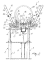
- the retention fixture particularly for retaining extrusion and drawing dies to be subjected to finishing operations, according to the invention, generally designated by the reference numeral 1, comprises a supporting framework that is generally designated by the reference numeral 2 and has a base frame 3 to which an upper frame 4 is connected; said upper frame is associated telescopically with the means for vertical adjustment in order to position the supporting surface 5 of the upper frame 4 at the selected level.
- the vertical adjustment means is a cylinder 6, which is connected to the frame 3 and has a stem 7 that engages the supporting surface 5.
- the fixture further comprises a concave region, generally designated by the reference numeral 10, which is connected to the supporting surface 5 by interposing a rotary joint, generally designated by the reference numeral 11, which allows rotation about a substantially vertical axis.
- an L-shaped element 12 is connected to the concave region 10 and engages the fixed part 13 of the rotary joint by means of a positioning bolt 14 that is connected to the L-shaped element 12.
- the concave region 10 is advantageously provided by means of a front plate 15 and a rear plate 16, which are spaced one another and are provided with a plurality of positioning holes 17 that allow to insert an initial locking bolt 18 that retains in position the die 20 in the initial steps for connection to the fixture.
- rollers 21 that have a fixed axis and are arranged in the central region; the means for rotating the die 20 about its own axis are arranged between said rollers and are advantageously constituted by a rubber roller 22 that is connected to a front actuation shank 23 that can be actuated by means of a crank or other tool in order to turn the die about its axis.
- the rollers 24 are designed to engage the peripheral region of the die 20 and can be locked in position by acting on locking means such as the end bolts 27 that allow their locking in position.
- the fixture comprises arms for preventing tipping, designated by the reference numeral 30, which are pivoted in a downward region to lugs 31 that are associated with the concave region 10.
- the arms 30, which are provided in a region that lies outside the region affected by the die 20, have a front arm 31a and a rear arm 31b, which are joined by cross-members 32, which support rollers 33 for engaging the front faces of the die.
- the cross-members 32 are provided with slots 34 that allow to position and lock in the preset position the rollers 33, which are therefore made to engage the faces of the die.
- the arms 30 can be locked in the preset position by means of an angular portion 35, which is arranged substantially at right angles to the arms 30 at its region for pivoting to the lugs 31 and has a fixing bolt 36 that can engage a positioning slot 37 formed monolithically with the concave region 10.
- the arms 30 are positioned according to the diameter of the die so that the bearings or rollers 33 that they support engage the front and rear faces of the die, which is therefore retained without the possibility to tip.
- the operator initially positions the supporting surface 5 at the selected height by acting on the cylinder 6.
- the die 20 is positioned in the concave region 10, and while the die is supported by means of the suspension hook 20a, which is then removed, the die is initially retained by inserting the locking bolt 18, which is passed through the front plate 15 and the rear plate 16 of the concave region 10.
- the arms 30 for preventing tipping are positioned so that the rollers or bearings 33 engage the peripheral region of the die.
- the plurality of rollers 24 with movable axes are fixed in position, so that the die is supported along a certain circumferential portion and is retained outside the concave region by the bearings 33.
- the bolt 18 is removed so that the die can be turned about its own axis by acting on the rubber roller 23 that allows to turn the die about its own axis through an angle of 360°.
- the invention achieves the intended aim and objects, and in particular the fact is stressed that the present structure allows to use the fixture with dies that have diameters comprised within a vast range, for example from 500 to 1200 mm, being always able to provide adequate and correct support for the die.
- the materials used, as well as the contingent shapes and dimensions may be any according to requirements.
Landscapes
- Engineering & Computer Science (AREA)
- General Engineering & Computer Science (AREA)
- Mechanical Engineering (AREA)
- Extrusion Moulding Of Plastics Or The Like (AREA)
Applications Claiming Priority (2)
| Application Number | Priority Date | Filing Date | Title |
|---|---|---|---|
| ITMI20032111 | 2003-10-31 | ||
| IT002111A ITMI20032111A1 (it) | 2003-10-31 | 2003-10-31 | Apparecchiatura per il trattenimento particolarmente di |
Publications (1)
| Publication Number | Publication Date |
|---|---|
| EP1536177A1 true EP1536177A1 (en) | 2005-06-01 |
Family
ID=34452254
Family Applications (1)
| Application Number | Title | Priority Date | Filing Date |
|---|---|---|---|
| EP04003003A Withdrawn EP1536177A1 (en) | 2003-10-31 | 2004-02-11 | Retention fixture, particularly for retaining extrusion and drawing dies to be subjected to finishing operations |
Country Status (2)
| Country | Link |
|---|---|
| EP (1) | EP1536177A1 (it) |
| IT (1) | ITMI20032111A1 (it) |
Citations (4)
| Publication number | Priority date | Publication date | Assignee | Title |
|---|---|---|---|---|
| GB783075A (en) * | 1952-12-17 | 1957-09-18 | Oskar Waldrich | Improvements in and relating to roll turning lathes |
| GB914241A (en) * | 1961-10-17 | 1962-12-28 | George Russell Whittenberg | Work supporting brackets for centreless grinders |
| FR2537245A1 (fr) * | 1982-12-02 | 1984-06-08 | Ziffel Alain | Traverse de reglage, notamment pour un vireur de chaudronnerie |
| EP0224419A1 (fr) * | 1985-10-18 | 1987-06-03 | INNOVATION POUR L'USINAGE SUR SITE -I PLUS (société à responsabilité limitée) | Procédé et dispositif d'usinage ou de contrôle sur site pour pièces rotatives |
-
2003
- 2003-10-31 IT IT002111A patent/ITMI20032111A1/it unknown
-
2004
- 2004-02-11 EP EP04003003A patent/EP1536177A1/en not_active Withdrawn
Patent Citations (4)
| Publication number | Priority date | Publication date | Assignee | Title |
|---|---|---|---|---|
| GB783075A (en) * | 1952-12-17 | 1957-09-18 | Oskar Waldrich | Improvements in and relating to roll turning lathes |
| GB914241A (en) * | 1961-10-17 | 1962-12-28 | George Russell Whittenberg | Work supporting brackets for centreless grinders |
| FR2537245A1 (fr) * | 1982-12-02 | 1984-06-08 | Ziffel Alain | Traverse de reglage, notamment pour un vireur de chaudronnerie |
| EP0224419A1 (fr) * | 1985-10-18 | 1987-06-03 | INNOVATION POUR L'USINAGE SUR SITE -I PLUS (société à responsabilité limitée) | Procédé et dispositif d'usinage ou de contrôle sur site pour pièces rotatives |
Also Published As
| Publication number | Publication date |
|---|---|
| ITMI20032111A1 (it) | 2005-05-01 |
Similar Documents
| Publication | Publication Date | Title |
|---|---|---|
| ITVR990033A1 (it) | Macchina monta-smontagomme per ruote di veicoli industriali. | |
| US7143801B2 (en) | Spindle for fastening rims of vehicle wheels on repair shop machines | |
| CA2630958A1 (en) | Adjustable roller frame | |
| ITRE20070091A1 (it) | '' macchina smontagomme perfezionata " | |
| EP2551131B1 (en) | Device for locking rims of a vehicle on supporting means of a tyre servicing machine | |
| EP3645212B1 (en) | An apparatus for supporting a heavy vehicle brake assembly | |
| CN202006357U (zh) | 一种用于焊装夹具的高低可调式旋转平台 | |
| KR101524033B1 (ko) | 포터블 대형 플랜지 가공장치 | |
| US9789583B2 (en) | Adjustable grinding jig | |
| CZ200578A3 (cs) | Zařízení pro připevnění držáku nástroje | |
| ITRE960028A1 (it) | Macchina per il montaggio e lo smontaggio dei pneumatici sui e dai rispettivi cerchioni | |
| KR101780623B1 (ko) | 러그 취부 장치 | |
| CN109531468B (zh) | 一种缸体钳修定位工装 | |
| CN218837691U (zh) | 一种用于钢结构加工的翻转装置 | |
| CN210553556U (zh) | 一种印花机的裁切装置 | |
| CN219212907U (zh) | 一种铜套加工夹持器 | |
| KR101498313B1 (ko) | 선미재 호닝용 에어드릴 지그 | |
| CN211163839U (zh) | 钳工用旋转式工作平台 | |
| EP3098092B1 (en) | Spindle for tire changing machines | |
| KR101636729B1 (ko) | 포트롤 안전 조립장치 | |
| JP5904956B2 (ja) | タイヤ着脱装置 | |
| CN210499334U (zh) | 一种轴类零件加工定位夹具 | |
| CN107030411B (zh) | 用于羊角式钢管总成的焊接装置 | |
| JP7191428B1 (ja) | 円管の端部加工機 | |
| CN220761749U (zh) | 一种立辊夹具的安装辅助工具 |
Legal Events
| Date | Code | Title | Description |
|---|---|---|---|
| PUAI | Public reference made under article 153(3) epc to a published international application that has entered the european phase |
Free format text: ORIGINAL CODE: 0009012 |
|
| AK | Designated contracting states |
Kind code of ref document: A1 Designated state(s): AT BE BG CH CY CZ DE DK EE ES FI FR GB GR HU IE IT LI LU MC NL PT RO SE SI SK TR |
|
| AX | Request for extension of the european patent |
Extension state: AL LT LV MK |
|
| STAA | Information on the status of an ep patent application or granted ep patent |
Free format text: STATUS: THE APPLICATION HAS BEEN WITHDRAWN |
|
| 18W | Application withdrawn |
Effective date: 20051012 |