EP1536199A1 - Couche balistique en céramique - Google Patents
Couche balistique en céramique Download PDFInfo
- Publication number
- EP1536199A1 EP1536199A1 EP03027067A EP03027067A EP1536199A1 EP 1536199 A1 EP1536199 A1 EP 1536199A1 EP 03027067 A EP03027067 A EP 03027067A EP 03027067 A EP03027067 A EP 03027067A EP 1536199 A1 EP1536199 A1 EP 1536199A1
- Authority
- EP
- European Patent Office
- Prior art keywords
- layer
- protective layer
- ballistic protective
- bombardment
- segments
- Prior art date
- Legal status (The legal status is an assumption and is not a legal conclusion. Google has not performed a legal analysis and makes no representation as to the accuracy of the status listed.)
- Granted
Links
- 239000000919 ceramic Substances 0.000 title abstract description 19
- 239000010410 layer Substances 0.000 claims description 110
- 239000011241 protective layer Substances 0.000 claims description 69
- 239000000463 material Substances 0.000 claims description 45
- 238000000034 method Methods 0.000 claims description 27
- 229910010293 ceramic material Inorganic materials 0.000 claims description 23
- 238000004519 manufacturing process Methods 0.000 claims description 22
- HBMJWWWQQXIZIP-UHFFFAOYSA-N silicon carbide Chemical compound [Si+]#[C-] HBMJWWWQQXIZIP-UHFFFAOYSA-N 0.000 claims description 21
- 229910010271 silicon carbide Inorganic materials 0.000 claims description 21
- 229920000049 Carbon (fiber) Polymers 0.000 claims description 20
- 239000004917 carbon fiber Substances 0.000 claims description 20
- 239000000835 fiber Substances 0.000 claims description 18
- 230000008569 process Effects 0.000 claims description 12
- 230000001681 protective effect Effects 0.000 claims description 10
- 238000005520 cutting process Methods 0.000 claims description 9
- 238000001035 drying Methods 0.000 claims description 9
- VNWKTOKETHGBQD-UHFFFAOYSA-N methane Chemical compound C VNWKTOKETHGBQD-UHFFFAOYSA-N 0.000 claims description 9
- 239000000203 mixture Substances 0.000 claims description 9
- 239000011226 reinforced ceramic Substances 0.000 claims description 9
- 229910052710 silicon Inorganic materials 0.000 claims description 8
- 239000010703 silicon Substances 0.000 claims description 8
- PZNSFCLAULLKQX-UHFFFAOYSA-N Boron nitride Chemical class N#B PZNSFCLAULLKQX-UHFFFAOYSA-N 0.000 claims description 5
- PNEYBMLMFCGWSK-UHFFFAOYSA-N aluminium oxide Inorganic materials [O-2].[O-2].[O-2].[Al+3].[Al+3] PNEYBMLMFCGWSK-UHFFFAOYSA-N 0.000 claims description 4
- 229910052751 metal Inorganic materials 0.000 claims description 4
- 239000002184 metal Substances 0.000 claims description 4
- 229920003043 Cellulose fiber Polymers 0.000 claims description 3
- 230000006378 damage Effects 0.000 claims description 3
- 229910052580 B4C Inorganic materials 0.000 claims description 2
- 229910052581 Si3N4 Inorganic materials 0.000 claims description 2
- WYTGDNHDOZPMIW-RCBQFDQVSA-N alstonine Natural products C1=CC2=C3C=CC=CC3=NC2=C2N1C[C@H]1[C@H](C)OC=C(C(=O)OC)[C@H]1C2 WYTGDNHDOZPMIW-RCBQFDQVSA-N 0.000 claims description 2
- 230000015572 biosynthetic process Effects 0.000 claims description 2
- INAHAJYZKVIDIZ-UHFFFAOYSA-N boron carbide Chemical compound B12B3B4C32B41 INAHAJYZKVIDIZ-UHFFFAOYSA-N 0.000 claims description 2
- 229910052575 non-oxide ceramic Inorganic materials 0.000 claims description 2
- 239000011225 non-oxide ceramic Substances 0.000 claims description 2
- 229910052574 oxide ceramic Inorganic materials 0.000 claims description 2
- 239000011224 oxide ceramic Substances 0.000 claims description 2
- 239000004033 plastic Substances 0.000 claims description 2
- 229920003023 plastic Polymers 0.000 claims description 2
- 238000000197 pyrolysis Methods 0.000 claims description 2
- HQVNEWCFYHHQES-UHFFFAOYSA-N silicon nitride Chemical compound N12[Si]34N5[Si]62N3[Si]51N64 HQVNEWCFYHHQES-UHFFFAOYSA-N 0.000 claims description 2
- MCMNRKCIXSYSNV-UHFFFAOYSA-N Zirconium dioxide Chemical compound O=[Zr]=O MCMNRKCIXSYSNV-UHFFFAOYSA-N 0.000 claims 2
- XUIMIQQOPSSXEZ-UHFFFAOYSA-N Silicon Chemical compound [Si] XUIMIQQOPSSXEZ-UHFFFAOYSA-N 0.000 claims 1
- 238000002144 chemical decomposition reaction Methods 0.000 claims 1
- 238000002485 combustion reaction Methods 0.000 claims 1
- 229910003460 diamond Inorganic materials 0.000 claims 1
- 239000010432 diamond Substances 0.000 claims 1
- 238000004090 dissolution Methods 0.000 claims 1
- 239000000126 substance Substances 0.000 claims 1
- 238000005979 thermal decomposition reaction Methods 0.000 claims 1
- 239000002759 woven fabric Substances 0.000 claims 1
- 238000007747 plating Methods 0.000 abstract 1
- 230000011218 segmentation Effects 0.000 description 15
- 238000000465 moulding Methods 0.000 description 8
- 238000005245 sintering Methods 0.000 description 6
- 150000001875 compounds Chemical class 0.000 description 5
- 239000012783 reinforcing fiber Substances 0.000 description 5
- 229910052582 BN Inorganic materials 0.000 description 4
- 238000006243 chemical reaction Methods 0.000 description 4
- 238000001816 cooling Methods 0.000 description 4
- 239000007788 liquid Substances 0.000 description 4
- 238000003825 pressing Methods 0.000 description 4
- 239000011230 binding agent Substances 0.000 description 3
- 238000003763 carbonization Methods 0.000 description 3
- 238000005336 cracking Methods 0.000 description 3
- 239000004744 fabric Substances 0.000 description 3
- 238000011049 filling Methods 0.000 description 3
- 239000011159 matrix material Substances 0.000 description 3
- 239000000047 product Substances 0.000 description 3
- 230000002787 reinforcement Effects 0.000 description 3
- OKTJSMMVPCPJKN-UHFFFAOYSA-N Carbon Chemical compound [C] OKTJSMMVPCPJKN-UHFFFAOYSA-N 0.000 description 2
- 239000000956 alloy Substances 0.000 description 2
- 229910045601 alloy Inorganic materials 0.000 description 2
- 239000004760 aramid Substances 0.000 description 2
- 229910052799 carbon Inorganic materials 0.000 description 2
- 238000010276 construction Methods 0.000 description 2
- 230000003628 erosive effect Effects 0.000 description 2
- -1 for example Substances 0.000 description 2
- 230000004048 modification Effects 0.000 description 2
- 238000012986 modification Methods 0.000 description 2
- 239000012778 molding material Substances 0.000 description 2
- TWNQGVIAIRXVLR-UHFFFAOYSA-N oxo(oxoalumanyloxy)alumane Chemical compound O=[Al]O[Al]=O TWNQGVIAIRXVLR-UHFFFAOYSA-N 0.000 description 2
- 238000002360 preparation method Methods 0.000 description 2
- 238000005475 siliconizing Methods 0.000 description 2
- 238000007669 thermal treatment Methods 0.000 description 2
- 208000031872 Body Remains Diseases 0.000 description 1
- 239000004372 Polyvinyl alcohol Substances 0.000 description 1
- 229910000831 Steel Inorganic materials 0.000 description 1
- 239000000853 adhesive Substances 0.000 description 1
- 230000001070 adhesive effect Effects 0.000 description 1
- 229920006231 aramid fiber Polymers 0.000 description 1
- 229920003235 aromatic polyamide Polymers 0.000 description 1
- 230000015556 catabolic process Effects 0.000 description 1
- 230000008859 change Effects 0.000 description 1
- 238000004140 cleaning Methods 0.000 description 1
- 239000011248 coating agent Substances 0.000 description 1
- 238000000576 coating method Methods 0.000 description 1
- 230000001419 dependent effect Effects 0.000 description 1
- 230000000694 effects Effects 0.000 description 1
- 235000013312 flour Nutrition 0.000 description 1
- 238000009472 formulation Methods 0.000 description 1
- 239000012634 fragment Substances 0.000 description 1
- 238000000227 grinding Methods 0.000 description 1
- 230000003116 impacting effect Effects 0.000 description 1
- 238000007373 indentation Methods 0.000 description 1
- 239000011261 inert gas Substances 0.000 description 1
- 230000008595 infiltration Effects 0.000 description 1
- 238000001764 infiltration Methods 0.000 description 1
- 230000001788 irregular Effects 0.000 description 1
- 239000012633 leachable Substances 0.000 description 1
- 150000002739 metals Chemical class 0.000 description 1
- 238000003801 milling Methods 0.000 description 1
- RVTZCBVAJQQJTK-UHFFFAOYSA-N oxygen(2-);zirconium(4+) Chemical compound [O-2].[O-2].[Zr+4] RVTZCBVAJQQJTK-UHFFFAOYSA-N 0.000 description 1
- 239000012466 permeate Substances 0.000 description 1
- 229920003229 poly(methyl methacrylate) Polymers 0.000 description 1
- 239000004926 polymethyl methacrylate Substances 0.000 description 1
- 229920002689 polyvinyl acetate Polymers 0.000 description 1
- 239000011118 polyvinyl acetate Substances 0.000 description 1
- 229920002451 polyvinyl alcohol Polymers 0.000 description 1
- 239000011347 resin Substances 0.000 description 1
- 229920005989 resin Polymers 0.000 description 1
- 239000007787 solid Substances 0.000 description 1
- 239000002904 solvent Substances 0.000 description 1
- 239000007858 starting material Substances 0.000 description 1
- 239000010959 steel Substances 0.000 description 1
- 238000005406 washing Methods 0.000 description 1
- XLYOFNOQVPJJNP-UHFFFAOYSA-N water Substances O XLYOFNOQVPJJNP-UHFFFAOYSA-N 0.000 description 1
- 239000013585 weight reducing agent Substances 0.000 description 1
- 239000002023 wood Substances 0.000 description 1
- 229910001928 zirconium oxide Inorganic materials 0.000 description 1
Images

Classifications
-
- F—MECHANICAL ENGINEERING; LIGHTING; HEATING; WEAPONS; BLASTING
- F41—WEAPONS
- F41H—ARMOUR; ARMOURED TURRETS; ARMOURED OR ARMED VEHICLES; MEANS OF ATTACK OR DEFENCE, e.g. CAMOUFLAGE, IN GENERAL
- F41H5/00—Armour; Armour plates
- F41H5/02—Plate construction
- F41H5/04—Plate construction composed of more than one layer
- F41H5/0414—Layered armour containing ceramic material
Definitions
- the invention relates to a ceramic ballistic protective layer for the protection of persons and objects, such as vehicles from fire, especially multiple fire, and other punctiform attacking mechanical loads, as well as methods for their Production.
- a classic ballistic material is steel in specific alloy forms. These alloys withstand hit distances of about three calibers even withstand multiple fire.
- the biggest disadvantage of such systems is the weight per unit area of the ballistic resistance class of eg approx. 70 kg / m 2 for the fire class FB 7.
- ceramic materials have a higher ballistic protective effect in relation to the density and the weight per unit area (about 35-45 kg / m 2 ).
- protective armor made of discrete ceramic Segments, so-called tiles, with lateral dimensions of the order of 100 mm x 100 mm to 20 mm x 20 mm. If hit, only the one hit will be hit Tile destroyed, the surrounding, decoupled by the gap between the adjacent tiles System remains largely intact. The destroyed area corresponds to the Extension of the struck tile.
- protective armor to DE 39 40 623 consists of individual armor elements, preferably ceramic tiles, by means of an adhesive with a protective backing, for example, a high-modulus material Aramid fibers are connected.
- the bombardment of an armor element after this is raised to the direction of impact of the projectile and falls towards the edges of the armor element.
- the bombardment area is called Spherical surface portion or formed as a pyramid or conical surface.
- DE 198 34 393 a consisting of a ceramic material plate element described for a ballistic protective device on at least one of its surfaces - on the side facing the shelling or on the shelling opposite side or on both sides - with individual, from each other by material webs spaced recesses is provided. This will result in a weight reduction of the protective armor reached. Also, if the pits on the the bombardment facing side, the impulse of the impinging projectile to the deflected protruding material webs and mostly destroyed. Preferred are the Wells arranged so that the stagnant webs form a grid.
- the present invention provides a ceramic ballistic protective layer provided, which can be displayed as a large area, possibly curved component and withstand multiple hits with low hit distance. Furthermore, the concerns The present invention A process for producing such a protective layer.
- the ceramic ballistic protective layer according to the invention points to the bombardment facing side on a closed surface, whereas the bombardment opposite surface is characterized by a segmentation of this surface extending into the interior of the protective layer, but the layer does not extend to penetrates to the opposite, the bombardment facing surface.
- the segment structure is either by material-removing process or by material displacing method or produced by wildcards.
- one of one Page outgoing not the layer in its entire thickness crossing segmentation obtainable in that in a running at elevated temperature process two solid interconnected layers whose thermal expansion coefficients differ are generated, so that in the subsequent cooling phase in the layer from the Material with the higher expansion coefficient cracks, which this layer in split individual segments, while the adjacent layer of the material with the lower coefficient of expansion remains crack-free.
- the protective layer according to the invention predominantly from the aspect their use for protection against bombardment is described, the invention is not on limited to this purpose.
- the protective layer according to the invention is also suitable to prevent other punctiform attacking mechanical loads. In the Therefore, the term "bombardment" is only an example of such description below To understand loads.
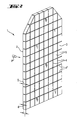
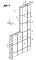
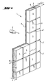
- the protective layer 1 according to the invention shown in Figures 1 to 4 according to claim 1 a total of about 5 to 150 mm thick.
- the Layer on a closed surface 2 On the side facing the bombardment P, the Layer on a closed surface 2, whereas the remote from the bombardment Surface 3 is characterized by a segmentation coming from this surface extending into the interior of the protective layer 1, but the opposite, the surface 2 facing the bombardment does not penetrate. That the depth T of the columns 4, 4 ' between the individual segments 5, from which the side facing away from the bombardment 3 is formed is smaller than the thickness D of the protective layer 1.
- the depth T of the Columns 4, 4 'between the segments 5 to be at least 0.15 mm smaller than the thickness D.
- the entire layer, i. between the floors 6, 6 'of the columns 4, 4' and the bombardment facing surface 2 must be material with a thickness d of at least 0.15 mm stay.
- the dimensions of the individual segments 5 are between 5 mm ⁇ 5 mm and 250 mm ⁇ 250 mm, with segments with dimensions between 10 mm x 10 mm to 150 mm x 150 mm are preferred. Larger segments are as described previously unsuitable for the Protection against multiple hits with low hit distance, while for smaller Segments of manufacturing costs increases sharply.
- the width of the column between the individual segments is between a few microns, if the column as cracks due uneven thermal expansion or drying and in 1/10 mm Range, if they are produced by means of mechanical processing should however, do not exceed 5 mm.
- the invention is not bound to any particular shape of the segments 5.
- the segments are for example, square, rectangular, parallelogram, polygonal, honeycomb, circular or elliptical.
- the segmented, the bombardment facing surface of the protective layer according to the invention is possibly on a base (so-called "backing"), which is used to catch Bullet fragments (splinters, projectile parts) and for the removal of residual energy is used.
- backing a base
- Bullet fragments splinters, projectile parts
- construction and manufacture of such backings are known in the art. Suitable materials for Production of such backings are z. As metal, aramid fabric or Dyneemagelege.
- the closed, not segmented surface of the protective layer according to the invention directly to the bombardment is exposed.
- the bombardment facing surface of the invention ballistic protective layer may be covered with one or more further layers, for example, ceramic layers.
- ceramic layers for example, ceramic layers.
- such an outer layer can also be made individual tiles are produced, but this variant because of the beginning mentioned economic disadvantages is not preferred.
- the protective layer according to the invention contains at least one ceramic material.
- Suitable materials for protective layers according to the invention are both oxide ceramics such as aluminum oxide and zirconium oxide and non-oxide ceramics such as boron carbide, boron nitride in one of the diamond-shaped high-temperature modifications, silicon nitride, silicon carbide and silicon-infiltrated silicon carbide (SiSiC).
- Particularly suitable are fiber-reinforced ceramics, such as aluminum oxide reinforced alumina, silicon carbide reinforced silicon carbide (SiC / SiC), or carbon fiber reinforced silicon carbide (C / SiC).
- Silicon carbide reinforced with carbon fibers is particularly preferred for the production of the protective layers according to the invention, because during the siliconization-in contrast to the material shrinkage during sintering of conventional ceramics-only relatively small changes in shape occur, so that a high contour accuracy can be achieved. This is particularly advantageous in the production of free-form components, for example curved components.
- the gaps between the segments are filled with a metal or / and a plastic or / and a ceramic material.
- the composition of the material in the gaps differs from the material of which the segments consist, such that the gap-filling material is different from the material whose fraction of the composition of the segments exceeds 50% by volume.
- the segments are made of siliconized ceramics, they also contain free silicon, but in a volume fraction of less than 50%.
- a protective layer according to the invention made of siliconized ceramics they can therefore be completely or partially filled with metallic silicon between the individual segments. "Partially filled” means that the gaps are not filled in their entire volume with the appropriate material.
- the protective layer 1 according to the invention is constructed homogeneously from one of the abovementioned materials and is provided with a segment structure by means of one of the methods according to the invention starting from the surface 3, the gaps 4, 4 'being interposed between the individual segments 5 do not extend through the entire thickness of the layer 1.
- the layer 1 according to the invention consists of two superimposed layers A and B fixedly connected to one another. The first layer A faces the bombardment and the second layer B faces away from the bombardment.
- Layer A has on its outwardly facing, the bombardment side facing a closed surface 2 without segmentation and column, while the outwardly facing, facing away from the bombard surface 3 of the layer B is segmented.
- the gaps 4, 4 'delimiting the individual segments 5 extend maximally through the entire thickness of the layer B up to the interface with the layer A.
- the layers A and B can differ in their composition.
- layer A is provided for the side facing the bombardment is made of a fiber reinforced ceramic, while facing away from the shelling, with the Segmentation to be provided layer B of a ceramic material without fiber reinforcement or with a smaller volume fraction of reinforcing fibers.
- the layer A facing the bombardment contains a volume fraction up to 60% of reinforcing fibers while facing away from the bombardment Layer B, the volume fraction of the reinforcing fibers is at most 45%.
- the volume fraction of the reinforcing fibers in the layer A is less than 50% and in of layer B below 20%.
- the volume fraction of the ceramic material in the bombardment facing away from fiber-reinforced layer B is at least 55%.
- binders such as resins, preferably pyrolyzable Binders and optionally residues of free carbide-forming metals, e.g. when it comes to a silicified ceramic is.
- this is the side facing away from the bombardment provided layer B of a material with a higher coefficient of thermal expansion than the material from which the side facing the bombardment is made Layer A is constructed.
- the layers with the different thermal Expansion coefficients are in a process occurring at elevated temperature generated.
- cracks form in the layer with the larger expansion coefficient, which divide this layer into segments. The cracks extend through the maximum entire thickness of the layer B to the interface with the layer A, which in turn free of cracks remains and for the shelling facing side is provided.
- layers A and B are made of carbon fiber reinforced, carbonizable molding compositions, wherein the fiber content in the layer A is higher than in the Layer B. Is this reinforced to varying degrees with fibers Layers A and B are then infiltrated with liquid silicon, so The conversion to silicon carbide in layers A and B is different Degrees. The lower the fiber content, the higher the degree of siliconization and the Conversion to silicon carbide.
- the layers A, which are siliconized to varying degrees, and B differ in their coefficients of thermal expansion. Because of the higher degree of siliconization, the thermal expansion of the layer B is greater, so that form cracks on cooling, which leads to a segmentation of this layer, while the Layer A remains closed. The crack formation can be determined by the degree of siliconation or Controlling the degree of conversion.
- the fiber reinforcement of the ceramic matrix can penetrate through into the molding compound in the desired Amount introduced short fibers are obtained.
- the segmentation of the layer according to the invention is carried out either on a suitable Intermediate stage of the manufacturing process or as a final process step.
- the segment structure on the surface facing away from the bombardment is, for example, by Material-removing processes such as milling, sawing, grinding, erosion, burn-out, laser beam cutting, Water jet cutting or similar produced.
- Material-removing processes such as milling, sawing, grinding, erosion, burn-out, laser beam cutting, Water jet cutting or similar produced.
- By means of one of these methods is on the side facing away from the bombardment according to the desired segment structure Material removed so that individual islands of material - the segments 5 - stop, between which narrow gaps 4, 4 ', from which the material has been removed, extend.
- These Processes are applied when the ceramic body has already solidified, ie e.g. after drying or after sintering of the green body.
- the material-removing structuring takes place either before or after the siliconization.
- the Un-silicided starting material is easier and easier to use work as the final silicized product.
- one has happened before the silicization Segmentation has the disadvantage that in the subsequent infiltration with liquid Silicon also at least partially fill the gaps between the segments with silicon can.
- This disadvantage is avoided if the columns are silicided by placeholders, For example, leachable materials are filled and blocked according to the Silicifying be removed.
- the finished silicided product is structured on one side, for example, mean erosion or laser beam cutting.
- a segment structure according to the invention is by material-displacing methods such as impressing, impressing or pressing the segment structure into the bombardment remote surface, for example by means of a correspondingly structured stamp or pressing tool available.
- Another material displacing suitable for the production of a segment structure Method is the cutting, in which the surface facing away from the bombardment by Cutting is segmented.
- Another method for segmenting the surface facing away from the bombardment consists in placing placeholders in this surface, if the ceramic material is still is malleable. These placeholders are poured, for example, into the surface, inserted or pressed in. The placeholders are placed in the surface in such a pattern, which corresponds to the course of the column between the segments to be produced. Preferably, bar-shaped placeholders are used, which are a grid, for example an orthogonal Grid, form. If the material has assumed a solidified state, the placeholders are replaced by leaving indentations in the surface away. For example, the placeholders after drying the ceramic Materials removed. Subsequently, the ceramic material is sintered. The sintering process is with a certain, to the extent of the composition of the ceramic Materials dependent shrinkage. This advantageously reduces the Width of the columns 4, 4 '.
- the placeholders consist of a sacrificial material, i. H. a dissolvable or chemically or thermally decomposable, for example pyrolyzable or combustible material and are used during one of the subsequent steps of the Manufacturing process, such as a thermal treatment or treatment removed with a solvent from the solidified material.
- a sacrificial material i. H. a dissolvable or chemically or thermally decomposable, for example pyrolyzable or combustible material
- a thermal treatment or treatment removed with a solvent from the solidified material such as a thermal treatment or treatment removed with a solvent from the solidified material.
- Placeholder of a virtually residue-free pyrolyzable material such as polyvinyl alcohol, Polyvinyl acetate, polymethyl methacrylate or polymethylmethacrylimide in the zu introduced segmenting surface.
- These placeholders are used during sintering pyrolyzed, leaving in the surface recesses back.
- Material-removing, material displacing and based on the use of wildcards Segmentation processes are both for the production of protective layers according to the invention with homogeneous structure according to Figures 1 to 3 and for the production two-layer protective layers of Figure 4 applicable.
- the layer B which is provided for the side facing away from the bombardment, with one of the aforementioned methods, so that a segment structure is obtained.
- two-layer protective layers according to the invention with a To provide one-sided segmentation is applicable when exposed to elevated temperature two successive layers A and layer B with different thermal Allow expansion coefficients to be generated.
- the side facing the shelling provided layer A has the smaller coefficient of thermal expansion.
- Will one Protective layer according to the invention thus constructed after a thermal treatment step, For example, after sintering or after siliconizing, cooled, so form in the Layer B of the material with the higher expansion coefficient cracks, which this Divide the layer into segments.
- the cracks traverse the layer B up to the maximum Interface to the layer A, which in turn thanks to their lower thermal expansion remains free of cracks.
- a ballistic protective layer according to the invention obtained, the surface facing the bombardment is closed while the Shield remote surface into individual, limited by the cracks segments structured is.
- the one-sided cracking is caused for example by the fact that the green body is heated more strongly during drying from one side than from the other.
- the protective layer according to the invention is suitable for the protection of persons, driving and Aircraft and other objects from shelling even in the case of multiple fire with small hit distance, or other types of point-attacking mechanical Burden. Another application of the protective layer according to the invention relates to Protection of satellites from mechanical destruction.
- a grid-shaped web system is introduced. This is in one Distance of about 1 mm above the bottom of the mold fixed.
- the webs that make up the grid is, have a distance of about 20 mm from each other, have a height of approx. 20 mm and form an orthogonal grid.
- the wall of the webs has a thickness of less than 1 mm.
- a sinterable ceramic mass is poured.
- the distance between the grid and the bottom of the mold is an independent leveling of the liquid mass instead.
- After drying leave at a temperature above 80 ° C remove the webs.
- the resulting green body has a closed on one side Surface, whereas the opposite surface with a segmentation having a pattern corresponding to the web system.
- Such green bodies can be sintered in a known manner. Due to the shrinkage of the Material during sintering reduces the width of the column, which occurs when removing the web system have remained, advantageously in the range of about 0.1 to 0.3 mm.
- the mold is prepared and filled as in Example 1, but the web system is made a residue-free pyrolysable material, which after drying first in the Green body remains and in the subsequent high-temperature process completely is pyrolyzed while column 4, 4 ', which enclose segments 5 leaves.
- a sinterable ceramic mass is placed in a mold and made into a green body pre-dried. Subsequently, a corresponding segmentation by impressing a Pattern, for example by means of a lattice-shaped pressing tool or Stamp, or introduced by cutting. The resulting segmentation permeates not the opposite surface.
- a prepared green body is in sintered in a known manner.
- a porous body of carbon fiber reinforced carbon (C / C) with a Total thickness of 8 mm is cut on one side with a cutter so that the cuts form a latticed pattern.
- the cutting depth is a maximum of 7.5 mm.
- the Sections are narrower than 1 mm. The sections were orthogonal in each case 20 mm distance introduced to each other.
- the sections were then filled with boron nitride (hexagonal modification) and the porous body of carbon fiber reinforced carbon (C / C) is infiltrated with liquid silicon in inert atmosphere or under inert gas.
- the Boron nitride filling in the gaps prevents them from filling with silicon.
- This Boron nitride acts during the silicification process as a placeholder, which subsequently is removed by washing.
- An approximately 4 mm high layer of short fiber reinforced carbonizable molding compound with a Volume fraction of 50% carbon fibers is introduced into a mold (layer A).
- the first layer (layer A) has a thickness of about 1 to 1.5 mm, the entire compact has one Height of about 14 mm. It is then carbonized at about 900 ° C.
- the molding compositions of the two layers are due to their different fiber content converted to silicon carbide to varying degrees in subsequent siliconization.
- the molding compound with the higher fiber content, the degree of conversion is lower forms a closed layer A, which is provided for the side facing the bombardment.
- the layer B Because of the higher thermal expansion coefficient of the higher silicided material in The layer B is formed during cooling in this layer to form cracks, which propagate across this layer to the interface with layer A.
- the by the Crack pattern segmented surface of layer B is for the side facing away from the bombardment intended.
- one of two carbon fiber reinforced ceramic layers A and B produced with different degrees of siliconation existing protective layer in the second layer (layer B), the fibers are in the form of a felt Carbon fibers present.
- one of two carbon fiber reinforced ceramic layers A and B produced with different degrees of siliconation existing protective layer.
- the molding compound used for the preparation of the layer B contains none Carbon fibers, but cellulose fibers, which in the carbonization of the molding material also be carbonized.
- a shaped body is produced and hardened.
- these moldings are at a distance of 15 mm orthogonal to each other arranged saw cuts with a cutting width of about 0.5 mm (saw blade width) such introduced that the depth of cut is about 2 mm lower than the component thickness. The saw blade the opposite side is thus not broken.
Landscapes
- Engineering & Computer Science (AREA)
- Chemical & Material Sciences (AREA)
- Ceramic Engineering (AREA)
- General Engineering & Computer Science (AREA)
- Aiming, Guidance, Guns With A Light Source, Armor, Camouflage, And Targets (AREA)
- Laminated Bodies (AREA)
- Inorganic Insulating Materials (AREA)
- Chemically Coating (AREA)
Priority Applications (5)
| Application Number | Priority Date | Filing Date | Title |
|---|---|---|---|
| DE50306975T DE50306975D1 (de) | 2003-11-25 | 2003-11-25 | Keramische ballistische Schutzschicht |
| ES03027067T ES2283701T3 (es) | 2003-11-25 | 2003-11-25 | Capa de ceramica de proteccion balistica. |
| EP03027067A EP1536199B1 (fr) | 2003-11-25 | 2003-11-25 | Couche balistique en céramique |
| AT03027067T ATE358807T1 (de) | 2003-11-25 | 2003-11-25 | Keramische ballistische schutzschicht |
| US10/988,735 US20050217471A1 (en) | 2003-11-25 | 2004-11-15 | Ceramic antiballistic layer, process for producing the layer and protective device having the layer |
Applications Claiming Priority (1)
| Application Number | Priority Date | Filing Date | Title |
|---|---|---|---|
| EP03027067A EP1536199B1 (fr) | 2003-11-25 | 2003-11-25 | Couche balistique en céramique |
Publications (2)
| Publication Number | Publication Date |
|---|---|
| EP1536199A1 true EP1536199A1 (fr) | 2005-06-01 |
| EP1536199B1 EP1536199B1 (fr) | 2007-04-04 |
Family
ID=34442868
Family Applications (1)
| Application Number | Title | Priority Date | Filing Date |
|---|---|---|---|
| EP03027067A Expired - Lifetime EP1536199B1 (fr) | 2003-11-25 | 2003-11-25 | Couche balistique en céramique |
Country Status (5)
| Country | Link |
|---|---|
| US (1) | US20050217471A1 (fr) |
| EP (1) | EP1536199B1 (fr) |
| AT (1) | ATE358807T1 (fr) |
| DE (1) | DE50306975D1 (fr) |
| ES (1) | ES2283701T3 (fr) |
Cited By (6)
| Publication number | Priority date | Publication date | Assignee | Title |
|---|---|---|---|---|
| WO2005114089A1 (fr) * | 2004-05-19 | 2005-12-01 | Deutsches Zentrum für Luft- und Raumfahrt e.V. | Plaque de blindage en ceramique, systeme de blindage et procede pour produire une plaque de blindage en ceramique |
| WO2007055736A3 (fr) * | 2005-05-26 | 2007-08-02 | Composix Co | Blindage multi-coup céramique |
| WO2008037623A1 (fr) * | 2006-09-27 | 2008-04-03 | Deutsches Zentrum für Luft- und Raumfahrt e.V. | Blindage céramique et procédé de fabrication d'un blindage céramique |
| WO2011101872A1 (fr) | 2010-02-16 | 2011-08-25 | Tecno Drive S.R.L. | Dispositif de levage, en particulier de levage de fauteuils roulants |
| WO2012063271A2 (fr) | 2010-11-10 | 2012-05-18 | Petroceramics S.P.A. | Élément antibalistique |
| FR3092659A1 (fr) * | 2019-02-13 | 2020-08-14 | Protecop | Vêtement de protection, par exemple gilet pare-balles, porte-plaque ou analogue |
Families Citing this family (39)
| Publication number | Priority date | Publication date | Assignee | Title |
|---|---|---|---|---|
| ATE370382T1 (de) * | 2001-07-25 | 2007-09-15 | Aceram Materials And Technolog | Keramische panzerungssysteme mit frontseitiger splitterfangschicht und dämpfungsschicht |
| US7562612B2 (en) * | 2001-07-25 | 2009-07-21 | Aceram Materials & Technologies, Inc. | Ceramic components, ceramic component systems, and ceramic armour systems |
| CA2483231C (fr) * | 2004-09-30 | 2011-11-29 | Aceram Technologies Inc. | Systeme de blindage en ceramique avec revetement de diamant |
| USD569043S1 (en) | 2006-01-12 | 2008-05-13 | Lineweight Llc | Ballistic armor back plate |
| USD569046S1 (en) * | 2006-01-26 | 2008-05-13 | Lineweight Llc | Ballistic body armor plate |
| USD568544S1 (en) * | 2006-01-26 | 2008-05-06 | Lineweight Llc | Ballistic body armor plate |
| USD573311S1 (en) | 2006-01-26 | 2008-07-15 | Lineweight Llc | Ballistic body armor plate |
| USD569044S1 (en) * | 2006-01-26 | 2008-05-13 | Lineweight Llc | Ballistic body armor plate |
| USD569045S1 (en) * | 2006-01-26 | 2008-05-13 | Lineweight Llc | Ballistic body armor plate |
| GB2439958A (en) * | 2006-07-11 | 2008-01-16 | Np Aerospace Ltd | Armour tile arrangement |
| GB2448477B (en) * | 2007-04-20 | 2012-11-07 | Np Aerospace Ltd | Vehicle armour |
| US9921037B2 (en) * | 2007-08-16 | 2018-03-20 | University Of Virginia Patent Foundation | Hybrid periodic cellular material structures, systems, and methods for blast and ballistic protection |
| GB0804487D0 (en) | 2008-03-11 | 2008-04-16 | Terram Ltd | Cellular structures |
| US20090250675A1 (en) * | 2008-03-24 | 2009-10-08 | Arthur Henry Cashin | Vehicle Barrier |
| US20090235814A1 (en) * | 2008-03-24 | 2009-09-24 | Cashin Arthur H | Mobile Reconfigurable Barricade |
| US20090235507A1 (en) * | 2008-03-24 | 2009-09-24 | Arthur Henry Cashin | Method Of Repairing A Ballistics Barrier |
| US20090235813A1 (en) * | 2008-03-24 | 2009-09-24 | Arthur Henry Cashin | Ballistics Barrier |
| ITFI20090130A1 (it) * | 2009-06-17 | 2010-12-18 | Ind Bitossi Spa | Componenti per corazze ceramiche. |
| US8375841B2 (en) | 2009-06-17 | 2013-02-19 | Industrie Bitossi, S.p.A. | Armor tile |
| CN102741646A (zh) * | 2010-02-01 | 2012-10-17 | Sgl碳股份公司 | 防御性的陶瓷基贴花装甲,提供抗射弹的装甲保护的装置,和生产具有中空几何形状的陶瓷基射弹装甲的方法 |
| IT1402004B1 (it) * | 2010-10-05 | 2013-08-28 | Beretta Armi Spa | Procedimento per la realizzazione di caricatori di armi da fuoco, in particolare pistole e/o simili, e caricatore ottenuto mediante tale procedimento |
| DE102010042812B3 (de) * | 2010-10-22 | 2012-04-05 | Schott Ag | Verfahren zur Herstellung einer Schutzvorrichtung |
| USD701821S1 (en) | 2010-12-16 | 2014-04-01 | Industrie Bitossi, S.p.A. | Armor tile |
| US20130180393A1 (en) * | 2011-02-01 | 2013-07-18 | Sgl Carbon Se | Defensive, ceramic based, applique armor, device for providing anti-projectile armoring protection and process for producing ceramic based projectile armor with hollow geometry |
| US20130010914A1 (en) * | 2011-07-08 | 2013-01-10 | Battelle Energy Alliance, Llc | Composite materials, bodies and nuclear fuels including metal oxide and silicon carbide and methods of forming same |
| GB2493007B (en) | 2011-07-21 | 2017-08-30 | Fiberweb Holdings Ltd | Confinement structures for particulate fill materials |
| GB2494457A (en) * | 2011-09-12 | 2013-03-13 | Ten Cate Advanced Armour Uk Ltd | Armour module for a vehicle |
| US9046325B1 (en) * | 2012-11-08 | 2015-06-02 | The United States Of America As Represented By The Secretary Of The Navy | Explosive blast frequency control shield and method |
| US20180010890A1 (en) * | 2013-02-21 | 2018-01-11 | Blake Lockwood Waldrop | Multi-layer multi-impact ballistic body armor and method of manufacturing the same |
| US9726459B2 (en) * | 2013-02-21 | 2017-08-08 | Rma Armament, Inc. | Multi-layer multi-impact ballistic body armor and method of manufacturing the same |
| US9389047B2 (en) * | 2013-04-26 | 2016-07-12 | E I Du Pont De Nemours And Company | Ballistic resistant armor article |
| CN103591846B (zh) * | 2013-11-18 | 2015-07-08 | 宁波伏尔肯机械密封件制造有限公司 | 一种整体式碳化硅陶瓷防弹板及其制造方法 |
| IL230775B (en) | 2014-02-02 | 2018-12-31 | Imi Systems Ltd | Pre-stressed curved ceramic panels/tiles and a method for their production |
| US10234243B2 (en) * | 2015-06-12 | 2019-03-19 | A. Jacob Ganor | Antiballistic armor comprising a super-hard strike face |
| US10942010B1 (en) * | 2017-07-27 | 2021-03-09 | Hrl Laboratories, Llc | Architected armor |
| US11378360B1 (en) * | 2018-06-07 | 2022-07-05 | Cornerstone Research Group, Inc. | Apparatuses and wearable armor systems including electrical sources |
| CN111850559B (zh) * | 2020-07-28 | 2022-09-13 | 中航装甲科技有限公司 | 一种提高陶瓷防弹能力的织构涂层及其制备方法 |
| US11754375B1 (en) | 2020-10-29 | 2023-09-12 | Cornerstone Research Group, Inc. | Apparatuses and wearable armor systems including electrical sources |
| CN117329927A (zh) * | 2023-11-14 | 2024-01-02 | 山东宝纳新材料有限公司 | 一种碳化硅防弹陶瓷内衬、其制备方法及应用 |
Citations (8)
| Publication number | Priority date | Publication date | Assignee | Title |
|---|---|---|---|---|
| US2348130A (en) * | 1941-02-07 | 1944-05-02 | Jr Charles J Hardy | Armor plating |
| GB2149482A (en) * | 1981-08-13 | 1985-06-12 | Harry Apprich | Projectile-proof material |
| WO1991007632A1 (fr) * | 1989-11-13 | 1991-05-30 | Allied-Signal Inc. | Blindage composite anti-balistique |
| DE3940623A1 (de) | 1989-12-08 | 1991-06-13 | Sst Sicherheits Und Systemtech | Panzerungselement fuer eine ballistische panzerplattenanordnung |
| DE3122367C1 (de) * | 1981-06-05 | 1994-12-22 | Deutsche Aerospace | Wand zum Schutz gegen Hohlladungen und Wuchtgeschosse |
| DE19834393A1 (de) | 1998-07-30 | 2000-02-03 | Etec Ges Fuer Tech Keramik Mbh | Plattenelement für eine Schutzeinrichtung |
| US6532857B1 (en) * | 2000-05-12 | 2003-03-18 | Ceradyne, Inc. | Ceramic array armor |
| WO2003043951A2 (fr) * | 2001-11-23 | 2003-05-30 | Sgl Carbon Ag | Corps composite renforce par fibres pour blindages de protection, sa production et ses utilisations |
Family Cites Families (11)
| Publication number | Priority date | Publication date | Assignee | Title |
|---|---|---|---|---|
| US2718829A (en) * | 1952-10-11 | 1955-09-27 | Atlas Mineral Products Company | Protective surface |
| US3607607A (en) * | 1968-05-27 | 1971-09-21 | Coors Porcelain Co | Organic resin ceramic composite and method for making same |
| US5686689A (en) * | 1985-05-17 | 1997-11-11 | Aeronautical Research Associates Of Princeton, Inc. | Lightweight composite armor |
| FR2655413B1 (fr) * | 1989-12-06 | 1994-06-03 | Europ Propulsion | Blindage de protection balistique. |
| US5326606A (en) * | 1992-08-12 | 1994-07-05 | Armorvision Plastics & Glass | Bullet proof panel |
| US5996115A (en) * | 1992-08-24 | 1999-12-07 | Ara, Inc. | Flexible body armor |
| EP0967453A1 (fr) * | 1998-06-25 | 1999-12-29 | Armortec Incorporated | Matériau flexible résistant à l'impact |
| US6969548B1 (en) * | 1999-08-30 | 2005-11-29 | Goldfine Andrew A | Impact absorbing composite |
| US6418832B1 (en) * | 2000-04-26 | 2002-07-16 | Pyramid Technologies International, Inc. | Body armor |
| ATE370382T1 (de) * | 2001-07-25 | 2007-09-15 | Aceram Materials And Technolog | Keramische panzerungssysteme mit frontseitiger splitterfangschicht und dämpfungsschicht |
| US6860186B2 (en) * | 2002-09-19 | 2005-03-01 | Michael Cohen | Ceramic bodies and ballistic armor incorporating the same |
-
2003
- 2003-11-25 EP EP03027067A patent/EP1536199B1/fr not_active Expired - Lifetime
- 2003-11-25 DE DE50306975T patent/DE50306975D1/de not_active Expired - Lifetime
- 2003-11-25 AT AT03027067T patent/ATE358807T1/de not_active IP Right Cessation
- 2003-11-25 ES ES03027067T patent/ES2283701T3/es not_active Expired - Lifetime
-
2004
- 2004-11-15 US US10/988,735 patent/US20050217471A1/en not_active Abandoned
Patent Citations (8)
| Publication number | Priority date | Publication date | Assignee | Title |
|---|---|---|---|---|
| US2348130A (en) * | 1941-02-07 | 1944-05-02 | Jr Charles J Hardy | Armor plating |
| DE3122367C1 (de) * | 1981-06-05 | 1994-12-22 | Deutsche Aerospace | Wand zum Schutz gegen Hohlladungen und Wuchtgeschosse |
| GB2149482A (en) * | 1981-08-13 | 1985-06-12 | Harry Apprich | Projectile-proof material |
| WO1991007632A1 (fr) * | 1989-11-13 | 1991-05-30 | Allied-Signal Inc. | Blindage composite anti-balistique |
| DE3940623A1 (de) | 1989-12-08 | 1991-06-13 | Sst Sicherheits Und Systemtech | Panzerungselement fuer eine ballistische panzerplattenanordnung |
| DE19834393A1 (de) | 1998-07-30 | 2000-02-03 | Etec Ges Fuer Tech Keramik Mbh | Plattenelement für eine Schutzeinrichtung |
| US6532857B1 (en) * | 2000-05-12 | 2003-03-18 | Ceradyne, Inc. | Ceramic array armor |
| WO2003043951A2 (fr) * | 2001-11-23 | 2003-05-30 | Sgl Carbon Ag | Corps composite renforce par fibres pour blindages de protection, sa production et ses utilisations |
Cited By (8)
| Publication number | Priority date | Publication date | Assignee | Title |
|---|---|---|---|---|
| WO2005114089A1 (fr) * | 2004-05-19 | 2005-12-01 | Deutsches Zentrum für Luft- und Raumfahrt e.V. | Plaque de blindage en ceramique, systeme de blindage et procede pour produire une plaque de blindage en ceramique |
| WO2007055736A3 (fr) * | 2005-05-26 | 2007-08-02 | Composix Co | Blindage multi-coup céramique |
| US7617757B2 (en) | 2005-05-26 | 2009-11-17 | Composix Co. | Ceramic multi-hit armor |
| WO2008037623A1 (fr) * | 2006-09-27 | 2008-04-03 | Deutsches Zentrum für Luft- und Raumfahrt e.V. | Blindage céramique et procédé de fabrication d'un blindage céramique |
| US7954417B2 (en) | 2006-09-27 | 2011-06-07 | Deutsches Zentrum Fuer Luft- Und Raumfahrt E.V. | Ceramic armoring and method for the production of ceramic armoring |
| WO2011101872A1 (fr) | 2010-02-16 | 2011-08-25 | Tecno Drive S.R.L. | Dispositif de levage, en particulier de levage de fauteuils roulants |
| WO2012063271A2 (fr) | 2010-11-10 | 2012-05-18 | Petroceramics S.P.A. | Élément antibalistique |
| FR3092659A1 (fr) * | 2019-02-13 | 2020-08-14 | Protecop | Vêtement de protection, par exemple gilet pare-balles, porte-plaque ou analogue |
Also Published As
| Publication number | Publication date |
|---|---|
| ATE358807T1 (de) | 2007-04-15 |
| EP1536199B1 (fr) | 2007-04-04 |
| DE50306975D1 (de) | 2007-05-16 |
| US20050217471A1 (en) | 2005-10-06 |
| ES2283701T3 (es) | 2007-11-01 |
Similar Documents
| Publication | Publication Date | Title |
|---|---|---|
| EP1536199B1 (fr) | Couche balistique en céramique | |
| DE102004026515A1 (de) | Keramische Panzerplatte, Panzersystem und Verfahren zur Herstellung einer keramischen Panzerplatte | |
| DE19621638C2 (de) | Offenzellige Schaumkeramik mit hoher Festigkeit und Verfahren zu deren Herstellung | |
| DE102004009262B4 (de) | Verfahren zur Herstellung eines mehrfach perforierten Teils aus einem Verbundwerkstoff mit Keramikmatrize | |
| EP1314708B1 (fr) | Corps moulé de matériaux composites renforcés par des fibres et ayant une couche supérieure segmentée, la préparation et l'utilisation du même | |
| DE10157487C1 (de) | Faserverstärkter Verbundkörper für Schutzpanzerungen, seine Herstellung und Verwendungen | |
| DE69325424T2 (de) | Verbundwerkstoff Vorform und Verfahren zur Herstellung eines faserverstärkten Verbundwerkstoffes | |
| DE69421568T2 (de) | Schleifender Werkzeugeinsatz | |
| DE69009015T2 (de) | Gepanzerter Sitz aus Verbundmaterialien und Verfahren zur Herstellung. | |
| DE69000125T2 (de) | Verfahren zum verbinden von elementen zur herstellung von teilen aus mehrstrukturellem verbundmaterial. | |
| DE19917175A1 (de) | Verfahren zum Herstellen eines Bauteiles und Bauteil | |
| EP1084997A2 (fr) | Matériau composite à matrice céramique renforcé par des faisceaux de fibres | |
| DE69403364T2 (de) | Verfahren zum Herstellen von Wärmeschutzelementen, insbesondere für Raumfahrzeuge | |
| DE10014418A1 (de) | Faserverstärktes Strukturbauteil | |
| DE19652223C2 (de) | Formkörper aus einem Werkstoffverbund, Verfahren zu seiner Herstellung und Verwendung | |
| DE3620178C2 (fr) | ||
| EP1876158A1 (fr) | Procédé destiné à la fabrication de composants carbocéramiques, éléments de tête composites destinés à la fabrication de composants en carbocéramique et composants en carbocéramique composites | |
| EP2069708A1 (fr) | Blindage céramique et procédé de fabrication d'un blindage céramique | |
| EP4074676A1 (fr) | Corps moulé composite à partir d'une céramique mixte liée par réaction, infiltrée au silicium | |
| DE102016219109A1 (de) | Partikel aus einem feuerfesten keramischen Werkstoff zur Beeinflussung der Rissbildung in Hochtemperaturwerkstoffen und Verfahren zu ihrer Herstellung | |
| DE10303351B3 (de) | Bauteil aus Metall/Keramik-Verbundwerkstoff mit intermetallischer Matrix, dessen Verwendung als Panzermaterial und Verfahren zu dessen Herstellung | |
| EP1369403B1 (fr) | Procédé de fabrication d'une pièce ayant une surface chargée tribologiquement | |
| DE3714240C1 (de) | Sinterformkoerper aus Siliciumnitrid mit einer aeusseren keramischen Nutzschicht auf der Basis von Aluminiumnitrid | |
| EP3141863B1 (fr) | Composant pour applications de protection balistique et son procede de fabrication | |
| DE102014224830B4 (de) | Brennkraftmaschine und Kraftfahrzeug |
Legal Events
| Date | Code | Title | Description |
|---|---|---|---|
| PUAI | Public reference made under article 153(3) epc to a published international application that has entered the european phase |
Free format text: ORIGINAL CODE: 0009012 |
|
| AK | Designated contracting states |
Kind code of ref document: A1 Designated state(s): AT BE BG CH CY CZ DE DK EE ES FI FR GB GR HU IE IT LI LU MC NL PT RO SE SI SK TR |
|
| AX | Request for extension of the european patent |
Extension state: AL LT LV MK |
|
| 17P | Request for examination filed |
Effective date: 20051201 |
|
| AKX | Designation fees paid |
Designated state(s): AT BE BG CH CY CZ DE DK EE ES FI FR GB GR HU IE IT LI LU MC NL PT RO SE SI SK TR |
|
| GRAP | Despatch of communication of intention to grant a patent |
Free format text: ORIGINAL CODE: EPIDOSNIGR1 |
|
| GRAS | Grant fee paid |
Free format text: ORIGINAL CODE: EPIDOSNIGR3 |
|
| GRAA | (expected) grant |
Free format text: ORIGINAL CODE: 0009210 |
|
| AK | Designated contracting states |
Kind code of ref document: B1 Designated state(s): AT BE BG CH CY CZ DE DK EE ES FI FR GB GR HU IE IT LI LU MC NL PT RO SE SI SK TR |
|
| PG25 | Lapsed in a contracting state [announced via postgrant information from national office to epo] |
Ref country code: SI Free format text: LAPSE BECAUSE OF FAILURE TO SUBMIT A TRANSLATION OF THE DESCRIPTION OR TO PAY THE FEE WITHIN THE PRESCRIBED TIME-LIMIT Effective date: 20070404 Ref country code: FI Free format text: LAPSE BECAUSE OF FAILURE TO SUBMIT A TRANSLATION OF THE DESCRIPTION OR TO PAY THE FEE WITHIN THE PRESCRIBED TIME-LIMIT Effective date: 20070404 |
|
| REG | Reference to a national code |
Ref country code: GB Ref legal event code: FG4D Free format text: NOT ENGLISH |
|
| REG | Reference to a national code |
Ref country code: CH Ref legal event code: EP |
|
| REF | Corresponds to: |
Ref document number: 50306975 Country of ref document: DE Date of ref document: 20070516 Kind code of ref document: P |
|
| REG | Reference to a national code |
Ref country code: IE Ref legal event code: FG4D Free format text: LANGUAGE OF EP DOCUMENT: GERMAN |
|
| REG | Reference to a national code |
Ref country code: CH Ref legal event code: NV Representative=s name: KELLER & PARTNER PATENTANWAELTE AG WINTERTHUR |
|
| PG25 | Lapsed in a contracting state [announced via postgrant information from national office to epo] |
Ref country code: SE Free format text: LAPSE BECAUSE OF FAILURE TO SUBMIT A TRANSLATION OF THE DESCRIPTION OR TO PAY THE FEE WITHIN THE PRESCRIBED TIME-LIMIT Effective date: 20070704 |
|
| GBT | Gb: translation of ep patent filed (gb section 77(6)(a)/1977) |
Effective date: 20070614 |
|
| PG25 | Lapsed in a contracting state [announced via postgrant information from national office to epo] |
Ref country code: PT Free format text: LAPSE BECAUSE OF FAILURE TO SUBMIT A TRANSLATION OF THE DESCRIPTION OR TO PAY THE FEE WITHIN THE PRESCRIBED TIME-LIMIT Effective date: 20070904 |
|
| NLV1 | Nl: lapsed or annulled due to failure to fulfill the requirements of art. 29p and 29m of the patents act | ||
| ET | Fr: translation filed | ||
| REG | Reference to a national code |
Ref country code: ES Ref legal event code: FG2A Ref document number: 2283701 Country of ref document: ES Kind code of ref document: T3 |
|
| PG25 | Lapsed in a contracting state [announced via postgrant information from national office to epo] |
Ref country code: NL Free format text: LAPSE BECAUSE OF FAILURE TO SUBMIT A TRANSLATION OF THE DESCRIPTION OR TO PAY THE FEE WITHIN THE PRESCRIBED TIME-LIMIT Effective date: 20070404 Ref country code: DK Free format text: LAPSE BECAUSE OF FAILURE TO SUBMIT A TRANSLATION OF THE DESCRIPTION OR TO PAY THE FEE WITHIN THE PRESCRIBED TIME-LIMIT Effective date: 20070404 Ref country code: BG Free format text: LAPSE BECAUSE OF FAILURE TO SUBMIT A TRANSLATION OF THE DESCRIPTION OR TO PAY THE FEE WITHIN THE PRESCRIBED TIME-LIMIT Effective date: 20070704 Ref country code: CZ Free format text: LAPSE BECAUSE OF FAILURE TO SUBMIT A TRANSLATION OF THE DESCRIPTION OR TO PAY THE FEE WITHIN THE PRESCRIBED TIME-LIMIT Effective date: 20070404 |
|
| PLBE | No opposition filed within time limit |
Free format text: ORIGINAL CODE: 0009261 |
|
| STAA | Information on the status of an ep patent application or granted ep patent |
Free format text: STATUS: NO OPPOSITION FILED WITHIN TIME LIMIT |
|
| PG25 | Lapsed in a contracting state [announced via postgrant information from national office to epo] |
Ref country code: SK Free format text: LAPSE BECAUSE OF FAILURE TO SUBMIT A TRANSLATION OF THE DESCRIPTION OR TO PAY THE FEE WITHIN THE PRESCRIBED TIME-LIMIT Effective date: 20070404 |
|
| 26N | No opposition filed |
Effective date: 20080107 |
|
| PG25 | Lapsed in a contracting state [announced via postgrant information from national office to epo] |
Ref country code: GR Free format text: LAPSE BECAUSE OF FAILURE TO SUBMIT A TRANSLATION OF THE DESCRIPTION OR TO PAY THE FEE WITHIN THE PRESCRIBED TIME-LIMIT Effective date: 20070705 |
|
| PG25 | Lapsed in a contracting state [announced via postgrant information from national office to epo] |
Ref country code: RO Free format text: LAPSE BECAUSE OF FAILURE TO SUBMIT A TRANSLATION OF THE DESCRIPTION OR TO PAY THE FEE WITHIN THE PRESCRIBED TIME-LIMIT Effective date: 20070404 |
|
| BERE | Be: lapsed |
Owner name: SGL CARBON A.G. Effective date: 20071130 |
|
| PG25 | Lapsed in a contracting state [announced via postgrant information from national office to epo] |
Ref country code: MC Free format text: LAPSE BECAUSE OF NON-PAYMENT OF DUE FEES Effective date: 20071130 |
|
| PG25 | Lapsed in a contracting state [announced via postgrant information from national office to epo] |
Ref country code: BE Free format text: LAPSE BECAUSE OF NON-PAYMENT OF DUE FEES Effective date: 20071130 |
|
| PG25 | Lapsed in a contracting state [announced via postgrant information from national office to epo] |
Ref country code: EE Free format text: LAPSE BECAUSE OF FAILURE TO SUBMIT A TRANSLATION OF THE DESCRIPTION OR TO PAY THE FEE WITHIN THE PRESCRIBED TIME-LIMIT Effective date: 20070404 |
|
| PG25 | Lapsed in a contracting state [announced via postgrant information from national office to epo] |
Ref country code: CY Free format text: LAPSE BECAUSE OF FAILURE TO SUBMIT A TRANSLATION OF THE DESCRIPTION OR TO PAY THE FEE WITHIN THE PRESCRIBED TIME-LIMIT Effective date: 20070404 |
|
| PG25 | Lapsed in a contracting state [announced via postgrant information from national office to epo] |
Ref country code: LU Free format text: LAPSE BECAUSE OF NON-PAYMENT OF DUE FEES Effective date: 20071125 |
|
| PG25 | Lapsed in a contracting state [announced via postgrant information from national office to epo] |
Ref country code: HU Free format text: LAPSE BECAUSE OF FAILURE TO SUBMIT A TRANSLATION OF THE DESCRIPTION OR TO PAY THE FEE WITHIN THE PRESCRIBED TIME-LIMIT Effective date: 20071005 Ref country code: TR Free format text: LAPSE BECAUSE OF FAILURE TO SUBMIT A TRANSLATION OF THE DESCRIPTION OR TO PAY THE FEE WITHIN THE PRESCRIBED TIME-LIMIT Effective date: 20070404 |
|
| PGFP | Annual fee paid to national office [announced via postgrant information from national office to epo] |
Ref country code: AT Payment date: 20091113 Year of fee payment: 7 Ref country code: CH Payment date: 20091124 Year of fee payment: 7 Ref country code: ES Payment date: 20091123 Year of fee payment: 7 Ref country code: IE Payment date: 20091124 Year of fee payment: 7 |
|
| PGFP | Annual fee paid to national office [announced via postgrant information from national office to epo] |
Ref country code: FR Payment date: 20091201 Year of fee payment: 7 Ref country code: GB Payment date: 20091119 Year of fee payment: 7 Ref country code: IT Payment date: 20091126 Year of fee payment: 7 |
|
| REG | Reference to a national code |
Ref country code: CH Ref legal event code: PL |
|
| GBPC | Gb: european patent ceased through non-payment of renewal fee |
Effective date: 20101125 |
|
| PG25 | Lapsed in a contracting state [announced via postgrant information from national office to epo] |
Ref country code: LI Free format text: LAPSE BECAUSE OF NON-PAYMENT OF DUE FEES Effective date: 20101130 Ref country code: CH Free format text: LAPSE BECAUSE OF NON-PAYMENT OF DUE FEES Effective date: 20101130 |
|
| REG | Reference to a national code |
Ref country code: FR Ref legal event code: ST Effective date: 20110801 |
|
| PG25 | Lapsed in a contracting state [announced via postgrant information from national office to epo] |
Ref country code: AT Free format text: LAPSE BECAUSE OF NON-PAYMENT OF DUE FEES Effective date: 20101125 |
|
| PG25 | Lapsed in a contracting state [announced via postgrant information from national office to epo] |
Ref country code: FR Free format text: LAPSE BECAUSE OF NON-PAYMENT OF DUE FEES Effective date: 20101130 Ref country code: IE Free format text: LAPSE BECAUSE OF NON-PAYMENT OF DUE FEES Effective date: 20101125 |
|
| PG25 | Lapsed in a contracting state [announced via postgrant information from national office to epo] |
Ref country code: GB Free format text: LAPSE BECAUSE OF NON-PAYMENT OF DUE FEES Effective date: 20101125 |
|
| PG25 | Lapsed in a contracting state [announced via postgrant information from national office to epo] |
Ref country code: IT Free format text: LAPSE BECAUSE OF NON-PAYMENT OF DUE FEES Effective date: 20101125 |
|
| REG | Reference to a national code |
Ref country code: ES Ref legal event code: FD2A Effective date: 20120110 |
|
| PG25 | Lapsed in a contracting state [announced via postgrant information from national office to epo] |
Ref country code: ES Free format text: LAPSE BECAUSE OF NON-PAYMENT OF DUE FEES Effective date: 20101126 |
|
| PGFP | Annual fee paid to national office [announced via postgrant information from national office to epo] |
Ref country code: DE Payment date: 20131121 Year of fee payment: 11 |
|
| REG | Reference to a national code |
Ref country code: DE Ref legal event code: R119 Ref document number: 50306975 Country of ref document: DE |
|
| PG25 | Lapsed in a contracting state [announced via postgrant information from national office to epo] |
Ref country code: DE Free format text: LAPSE BECAUSE OF NON-PAYMENT OF DUE FEES Effective date: 20150602 |