EP1536221A2 - Optical analyzer for improving resolution of a time-varying spectrum and method therefor - Google Patents
Optical analyzer for improving resolution of a time-varying spectrum and method therefor Download PDFInfo
- Publication number
- EP1536221A2 EP1536221A2 EP04257269A EP04257269A EP1536221A2 EP 1536221 A2 EP1536221 A2 EP 1536221A2 EP 04257269 A EP04257269 A EP 04257269A EP 04257269 A EP04257269 A EP 04257269A EP 1536221 A2 EP1536221 A2 EP 1536221A2
- Authority
- EP
- European Patent Office
- Prior art keywords
- vector
- spectrum
- gain
- resolution
- offset
- Prior art date
- Legal status (The legal status is an assumption and is not a legal conclusion. Google has not performed a legal analysis and makes no representation as to the accuracy of the status listed.)
- Granted
Links
Images


Classifications
-
- G—PHYSICS
- G01—MEASURING; TESTING
- G01J—MEASUREMENT OF INTENSITY, VELOCITY, SPECTRAL CONTENT, POLARISATION, PHASE OR PULSE CHARACTERISTICS OF INFRARED, VISIBLE OR ULTRAVIOLET LIGHT; COLORIMETRY; RADIATION PYROMETRY
- G01J3/00—Spectrometry; Spectrophotometry; Monochromators; Measuring colours
- G01J3/28—Investigating the spectrum
-
- G—PHYSICS
- G01—MEASURING; TESTING
- G01N—INVESTIGATING OR ANALYSING MATERIALS BY DETERMINING THEIR CHEMICAL OR PHYSICAL PROPERTIES
- G01N21/00—Investigating or analysing materials by the use of optical means, i.e. using sub-millimetre waves, infrared, visible or ultraviolet light
- G01N21/17—Systems in which incident light is modified in accordance with the properties of the material investigated
- G01N21/25—Colour; Spectral properties, i.e. comparison of effect of material on the light at two or more different wavelengths or wavelength bands
- G01N21/31—Investigating relative effect of material at wavelengths characteristic of specific elements or molecules, e.g. atomic absorption spectrometry
Definitions
- the present invention relates to a spectroscopic analyzing apparatus and method. More particularly, the present invention relates to a method and apparatus for improving a resolution of a time-varying spectrum.
- a spectroscopic analyzing method In a spectroscopic analyzing method, light is projected onto a specimen and a reference material, respectively. The respective detected spectrum amplitudes are compared, and the components of the specimen are analyzed. In reviewing an entire spectral band of a specimen, a main component of the specimen has a meaningful spectrum, which is isolated from the remaining components. By analyzing the amplitude of this meaningful spectrum, the components of the specimen and the content of each of the components can be estimated.
- One conventional spectroscopic analyzing method uses infrared radiation from a lamp passing through selected filters so that a specific frequency of radiation is incident upon a sample.
- a photocell detects the reflected signals, and the detected signals are amplified and output through an amplifier.
- a gain error of the amplifier is compensated for with a sample and hold circuit.
- each channel has its own corresponding sample and hold circuit. Thus, as the number of channels increases, fabrication cost of the spectral analysis system increases.
- a spectrum is detected using a plurality of amplifiers.
- the plurality of amplifiers complicates the system, and the addition of channels causes the overall operating costs to be increased. Also, since each of the plurality of amplifiers has a gain error, the accuracy of the analysis is reduced.
- spectral amplitude of a specimen being analyzed has a constant size, a spectrum may be readily analyzed by amplifying an optical signal. However, if the spectral amplitudes of the specimen vary across the spectrum, the signal-to-noise ratio (SNR) may not be sufficiently high to analyze the entire spectrum. Accordingly, analysis of that specimen component should be abandoned or another wavelength should be selected.
- SNR signal-to-noise ratio
- a method of analyzing a spectroscopic component including projecting light onto a specimen, detecting an optical spectrum from the specimen, temporally dividing the detected spectrum to form a plurality of spectra, applying a weighting vector and a gain and offset vector to each of the plurality of spectra to generate a resolution vector, quantizing the resolution vector to obtain a digital signal, and applying a synthesis vector to the quantized spectra to restore each quantized spectra to an original form of a corresponding spectra.
- the weighting vector may select a spectral ROI (region of interest) to increase resolution in a corresponding spectrum of the plurality of spectra obtained by dividing.
- the gain and offset vector may amplify the corresponding spectrum of the ROI to adjust a peak amplitude of the corresponding spectrum into a dynamic active region.
- a method for analyzing a spectroscopic component including projecting light onto a specimen, detecting an optical spectrum from the specimen, temporally dividing the detected spectrum into a plurality of spectra, generating a weighting vector representing a region of interest (ROI) from the divided spectra, generating a gain and offset vector for amplifying an original form of each spectra of the ROI, generating a synthesis vector for restoring the divided spectra to the original form thereof, multiplying the weighting vector by the optical spectrum to generate an ROI vector, multiplying the gain and offset vector by the ROI vector to generate a resolution vector, multiplying the resolution vector by the synthesis vector to generate a restoring vector, and adding the restoring vectors to obtain a spectrum of the original form having enhanced resolution.
- ROI region of interest
- the gain and offset vector may amplify the corresponding spectrum of the ROI to adjust a peak amplitude of the corresponding spectrum into a dynamic active region.
- the invention also relates to a spectroscopic analyzer, including a light source, a specimen, a detector which detects an optical spectrum generated by projecting light from the light source to the specimen, a spectral weighting block which adjusts a weighting vector and a gain and offset vector with respect to a region of interest (ROI) of the optical spectrum, an up-down resolution block which amplifies the optical spectrum detected by the detector to generate a resolution vector in accordance with the weighting vector and the gain and offset vector, an analog-to-digital converter which receives the resolution vector output from the up-down resolution block, and converts the received resolution vector to a digital signal, and a spectrum synthesis block which multiplies an output of the analog-digital converter by a synthesis vector for restoring the optical spectrum to an original form to generate a restoring vector and adding the restoring vector to the output of the analog-digital converter to output a spectrum having the original form and enhanced resolution.
- ROI region of interest
- the weighting vector may select a region having a relatively small amplitude, and, thus, a relatively low resolution, in the optical spectra divided by a predetermined time interval as the ROI.
- the gain and offset vector may amplify the corresponding spectrum of the ROI to adjust a peak amplitude of the corresponding spectrum into a dynamic active region.
- the up-down resolution block may include a gain control unit which receives the gain vector from the spectral weighting block, an offset control unit which receives the offset vector from the spectral weighting block, and an amplifying unit which amplifies the spectrum of the ROI in accordance with the gain vector and the offset vector.
- a spectrum having a large amplitude difference is divided by a time interval and is analyzed by differentially applying the resolution by the time interval. Accordingly, the resolution, preciseness and SNR of the spectral ROI are enhanced.
- the related art spectroscopic analyzer causes the system construction thereof to be large and to be expensive, while an embodiment of the inventive analyzer allows the system construction thereof to be small and inexpensive.
- an embodiment of the inventive analyzing method decreases the measurement time of the spectrum, noise influence due to drift is reduced compared with the related art analyzing method.
- the present invention is therefore directed to a spectroscopic analyzing method and apparatus, which aims to overcome one or more of the problems due to the limitations and disadvantages of the related art.
- ROI spectral region of interest
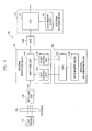
- FIG. 1 illustrates a block diagram of a spectroscopic analyzing apparatus according to an embodiment of the present invention.
- a spectroscopic analyzer 100 includes a light source 110, a specimen 120, a detecting unit 130, an up/down resolution block 140, a spectral region of interest (ROI) weighting block 150, an analog-to-digital (A/D) converter 160, and a spectral synthesis block 170.
- ROI spectral region of interest
- A/D analog-to-digital
- the detecting unit 130 converts an optical signal into an electrical signal. Electrical signals are generally expressed as a variation of voltage, and the voltage variation with respect to time is referred to as a spectrum signal. Since the voltage variation detected by the detecting unit 140 is small, the spectrum signal is modified by the up/down resolution block 140.
- the up/down resolution block 140 includes an amplifying unit 142, a gain control unit 144, and an offset control unit 146.
- the amplifying unit 142 amplifies an output spectrum signal x(n) of the detecting unit 130 and adjusts the size of the amplified signal to be matched with a dynamic active region, i.e., such that the signal can be stably amplified.
- the spectrum signal amplified by the amplifying unit 142 can be divided by a time interval depending on time or by a predetermined time interval.
- the spectra obtained by dividing the spectrum into time intervals can be amplified by the amplifying unit 142 by different values, i.e., by a gain value and an offset value that are control signals provided by the gain control unit 144 and the offset control unit 146.
- the control signals of the gain control unit 144 and the offset control unit 146 are provided from the spectral ROI weighting block 150.
- the spectral ROI weighting block 150 includes a CPU 152 and a data memory block 154.
- the data memory block 154 stores gain and offset values relative to positions in the waveform, which are read by the CPU 152 and output to the respective gain control unit 144 and the offset control unit 146.
- the spectral ROI weighting block 150 selects a spectral wavelength band to be used for the analysis of the specimen on the spectrum of the specimen 120 and divides the spectrum depending on time according to the selected wavelength band.
- the spectral portion having increased resolution is determined by a weighting vector generated in the spectral ROI weighting block 150. This weighting vector is provided to the gain control unit 144 and the offset control unit 146.
- the A/D converter 160 quantizes the amplified spectrum to convert it into a digital signal and transfers the quantized digital signal to the spectral synthesis block 170.
- the spectral synthesis block 170 includes a CPU 172 and a data memory block 174. The position in the waveform at which different amplification parameters are to be used remains the same for the reverse conversion performed by the spectral synthesis block 170. This position, as well as the reverse conversion information for the gain and offset values, is stored in the data memory block 174.
- the spectral synthesis block 170 synthesizes the spectrum having a resolution applied differentially depending on a time interval in the up/down resolution block 140 to an original shaped spectrum.
- the functions of the spectral ROI weighting block 150 and the spectral synthesis block 170 may be performed by the same CPU and data memory block.
- a spectral portion to receive enhanced resolution is selected in step 210.
- the original spectrum x(n) is divided by a time interval at step 220.
- a weighting vector W is constructed with reference to the divided time interval at step 230.
- a vector R which varies the gain and offset of the x(n) spectrum depending on the weighting vector W and the time interval is constructed at step 240. For example, the offset adjustment may be selected to ensure that an amplified spectrum remains within the dynamic active region.
- a vector S for restoring the divided spectrum to the original size spectrum is constructed at step 250.
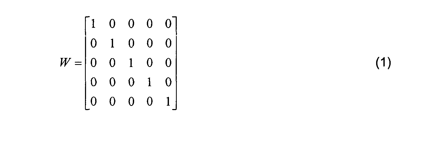
- the spectral ROI weighting block 150 multiplies the weighting vector W with the original spectrum x(n) received from the detecting unit (see 130 of FIG. 1) to thereby generate an ROI vector v(n).
- An example of the weighting vector W is shown in Equation (1) below:
- FIG. 4 illustrates the weighting vector W and the ROI vector v(n) with respect to the original spectrum x(n). While the resolution of the second ROI vector ⁇ 1 (n) allows eight gradations to be determined, the resolution of the fourth ROI vector ⁇ 3 (n) only allows three gradations to be determined. This discrepancy arises because a peak of the fourth ROI vector ⁇ 3 (n) is smaller than that of the second ROI vector ⁇ 1 (n).
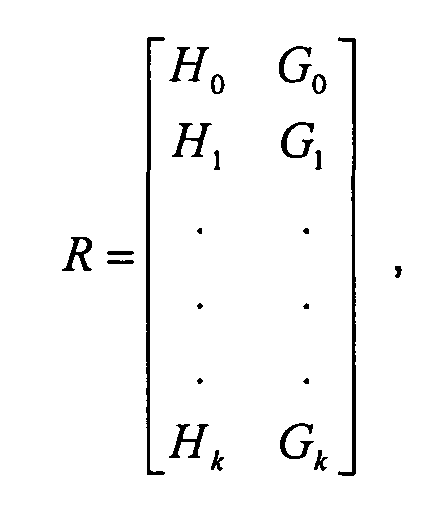
- the up/down resolution block 140 receives the ROI vector v(n) and generates a resolution vector r(n) by performing a predetermined functional product of the received ROI vector v(n) and the gain and offset vector R having a gain component H and an offset component G.
- the gain and offset vector R is defined by Equation (3) below:
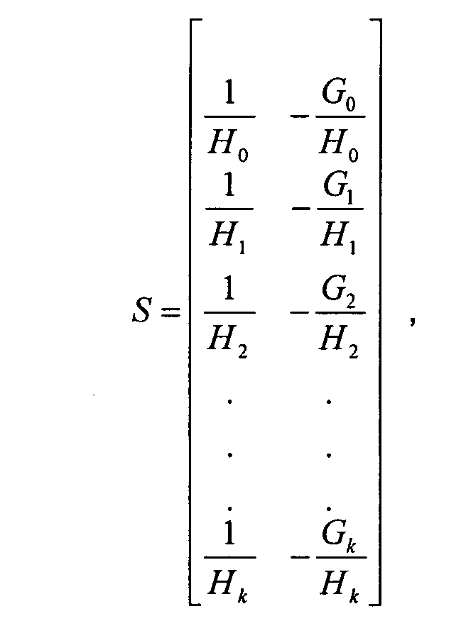
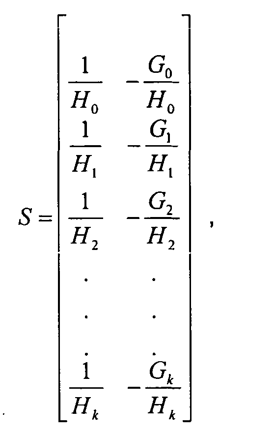
- the functional product of the resolution vector r(n) and the synthesis vector S for restoring a quantized vector to the size of the original vector x(n) is performed to generate a restoring vector z(n).
- the synthesis vector S is defined by Equation (5) below:
- a restored spectrum x ( n ) including a spectral portion with enhanced resolution is obtained by combining the spectral portions of z(n), as indicated in FIG. 3.
- the restored spectrum again has amplitudes and shapes, i.e., form, of the original spectrum x(n).
- FIG. 5 shows the resolution vector r(n) and the restoring vector z (n) with respect to the original spectrum x(n).
- the resolution of the fourth ROI vector v 3 (n) which only aiiowed three gradations in FIG. 4, is enhanced to allow seven gradations.
- the gain and offset vector R may be given by:
- a method for enhancing the resolution of the spectrum by a time interval using the spectroscopic analyzer 100 can be summarized as shown in FIG. 6.
- Light from the light source 110 is projected onto the specimen 120 at step 610.
- Light from the specimen 120 is detected by the detecting unit 130 at step 620, which outputs a spectrum.
- the spectrum is temporally divided into a plurality of spectra at step 630 in accordance with the weighting vector W.
- the gain and offset of each spectra is adjusted in the up/down resolution block 140 in accordance with the gain and offset vector R and the weighting vector W in step 630 to form a resolution vector, with a resolution component for each spectra.
- the resolution vector is quantized by the A/D converter 160 at step 640.
- the quantized spectra, having an enhanced resolution are synthesized to form restoring spectra having enhanced resolution and the original form at step 650.
- the enhanced resolution of the restored spectra is maintained.
- the resolution enhanced spectrum is formed by combining the restored spectra at step 660.
Landscapes
- Physics & Mathematics (AREA)
- Spectroscopy & Molecular Physics (AREA)
- General Physics & Mathematics (AREA)
- Biochemistry (AREA)
- Chemical & Material Sciences (AREA)
- Analytical Chemistry (AREA)
- Life Sciences & Earth Sciences (AREA)
- General Health & Medical Sciences (AREA)
- Health & Medical Sciences (AREA)
- Immunology (AREA)
- Pathology (AREA)
- Spectrometry And Color Measurement (AREA)
- Investigating Or Analysing Materials By Optical Means (AREA)
Abstract
Description


Claims (18)
- A method of analyzing a spectroscopic component, the method comprising:projecting light onto a specimen;detecting an optical spectrum from the specimen;temporally dividing the detected spectrum to form a plurality of spectra;applying a weighting vector and a gain and offset vector to each of the plurality of spectra to generate a resolution vector;quantizing the resolution vector to obtain a digital signal; andapplying a synthesis vector to the quantized spectra to restore each quantized spectrum to an original form of a corresponding original spectrum.
- The method as claimed in claim 1, wherein the weighting vector selects a spectral ROI (region of interest) to increase resolution in a corresponding spectrum of the plurality of spectra obtained by dividing.
- The method as claimed in claim 2, wherein the gain and offset vector amplifies the corresponding spectrum of the ROI to adjust a peak amplitude of the corresponding spectrum into a dynamic active region.
- The method as claimed in any preceding claim, wherein the resolution vector is expressed by r(n) = F[R, v(n)] = H • v(n) + G, in which the gain and offset vector R is expressed bywhere H is the gain and G is the offset.

- The method as claimed in any of claims 1 to 3, wherein the synthesis vector S is expressed bywhere H is the gain and G is the offset.
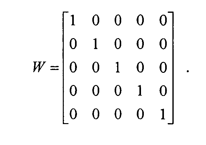
- The method as claimed in any preceding claim, wherein the weighting vector is expressed by

- A method for analyzing a spectroscopic component, the method comprising:projecting light onto a specimen;detecting an optical spectrum from the specimen;temporally dividing the detected spectrum into a plurality of spectra;generating a weighting vector representing a region of interest (ROI) from the divided spectra;generating a gain and offset vector for amplifying an original form of each spectrum of the ROI;generating a synthesis vector for restoring the divided spectra to the original form thereof;multiplying the weighting vector by the optical spectrum to generate an ROI vector;multiplying the gain and offset vector by the ROI vector to generate a resolution vector;multiplying the resolution vector by the synthesis vector to generate a restoring vector; andadding the restoring vectors to obtain a spectrum of the original form having enhanced resolution.
- The method as claimed in claim 7, wherein the gain and offset vector amplifies the corresponding spectrum of the ROI to adjust a peak amplitude of the corresponding spectrum into a dynamic active region.
- The method as claimed in claim 7 or 8, wherein the weighting vector is expressed by
- The method as claimed in claims 7, 8 or 9, wherein the resolution vector is expressed by r(n) = F[R,v(n)] = H • υ(n)+G , in which the gain and offset vector R is expressed bywhere G is the gain and H is the offset.
- The method as claimed in claims 7, 8 or 9, wherein the synthesis vector S is expressed bywhere H is the gain and G is the offset.
- A spectroscopic analyzer, comprising:a light source;a specimen;a detector which detects an optical spectrum generated by projecting light from the light source to the specimen;a spectral weighting block which adjusts a weighting vector and a gain and offset vector with respect to a region of interest (ROI) of the optical spectrum;an up-down resolution block which amplifies the optical spectrum detected by the detector to generate a resolution vector in accordance with the weighting vector and the gain and offset vector;an analog-to-digital converter which receives the resolution vector output from the up-down resolution block, and converts the received resolution vector to a digital signal; anda spectrum synthesis block which multiplies an output of the analog-digital converter by a synthesis vector for restoring the optical spectrum to an original form to generate a restoring vector and adding the restoring vector to the output of the analog-digital converter to output a spectrum having the original form and enhanced resolution.
- The spectroscopic analyzer as claimed in claim 12, wherein the weighting vector selects a region having a relatively small amplitude, and, thus, a relatively low resolution, in the optical spectra divided by a predetermined time interval as the ROI.
- The spectroscopic analyzer as claimed in claim 12 or 13, wherein the gain and offset vector amplifies the corresponding spectrum of the ROI to adjust a peak amplitude of the corresponding spectrum into a dynamic active region.
- The spectroscopic analyzer as claimed in claim 12, 13 or 14 wherein the up-down resolution block comprises:a gain control unit which receives the gain vector from the spectral weighting block;an offset control unit which receives the offset vector from the spectral weighting block; andan amplifying unit which amplifies the spectrum of the ROI in accordance with the gain vector and the offset vector.
- The spectroscopic analyzer as claimed in any of claims 12 to 15, wherein the weighting vector is expressed by

- The spectroscopic analyzer as claimed in any of claims 12 to 16, wherein the resolution vector is expressed by r(n) = F[R,υ(n)] = H • υ(n) + G, in which the gain and offset vector R is expressed bywhere H is the gain and G is the offset.

- The spectroscopic analyzer as claimed in any of claims 12 to 17, wherein the synthesis vector S is expressed bywhere H is the gain and G is the offset.

Applications Claiming Priority (2)
| Application Number | Priority Date | Filing Date | Title |
|---|---|---|---|
| KR20030085825A KR100571825B1 (en) | 2003-11-28 | 2003-11-28 | Spectral component analysis method and apparatus for improving resolution of variable spectrum |
| KR2003085825 | 2003-11-28 |
Publications (3)
| Publication Number | Publication Date |
|---|---|
| EP1536221A2 true EP1536221A2 (en) | 2005-06-01 |
| EP1536221A3 EP1536221A3 (en) | 2006-04-19 |
| EP1536221B1 EP1536221B1 (en) | 2016-09-21 |
Family
ID=34464772
Family Applications (1)
| Application Number | Title | Priority Date | Filing Date |
|---|---|---|---|
| EP04257269.3A Expired - Lifetime EP1536221B1 (en) | 2003-11-28 | 2004-11-24 | Optical analyzer for improving resolution of a time-varying spectrum and method therefor |
Country Status (4)
| Country | Link |
|---|---|
| US (1) | US7245372B2 (en) |
| EP (1) | EP1536221B1 (en) |
| JP (1) | JP2005164589A (en) |
| KR (1) | KR100571825B1 (en) |
Cited By (1)
| Publication number | Priority date | Publication date | Assignee | Title |
|---|---|---|---|---|
| CN108932923A (en) * | 2018-07-03 | 2018-12-04 | 深圳市华星光电半导体显示技术有限公司 | The detecting system and method for detecting of AMOLED |
Families Citing this family (18)
| Publication number | Priority date | Publication date | Assignee | Title |
|---|---|---|---|---|
| KR100763602B1 (en) * | 2006-03-16 | 2007-10-04 | 엘에스산전 주식회사 | How to adjust digital data resolution |
| CN104040309B (en) | 2011-11-03 | 2019-06-07 | 威利食品有限公司 | Inexpensive spectrometric system for end user's food analysis |
| GB2543655B (en) | 2013-08-02 | 2017-11-01 | Verifood Ltd | Compact spectrometer comprising a diffuser, filter matrix, lens array and multiple sensor detector |
| WO2015101992A2 (en) | 2014-01-03 | 2015-07-09 | Verifood, Ltd. | Spectrometry systems, methods, and applications |
| EP3209983A4 (en) | 2014-10-23 | 2018-06-27 | Verifood Ltd. | Accessories for handheld spectrometer |
| WO2016125165A2 (en) | 2015-02-05 | 2016-08-11 | Verifood, Ltd. | Spectrometry system with visible aiming beam |
| WO2016125164A2 (en) | 2015-02-05 | 2016-08-11 | Verifood, Ltd. | Spectrometry system applications |
| WO2016162865A1 (en) | 2015-04-07 | 2016-10-13 | Verifood, Ltd. | Detector for spectrometry system |
| US10066990B2 (en) | 2015-07-09 | 2018-09-04 | Verifood, Ltd. | Spatially variable filter systems and methods |
| US10203246B2 (en) | 2015-11-20 | 2019-02-12 | Verifood, Ltd. | Systems and methods for calibration of a handheld spectrometer |
| US10254215B2 (en) | 2016-04-07 | 2019-04-09 | Verifood, Ltd. | Spectrometry system applications |
| EP3488204A4 (en) | 2016-07-20 | 2020-07-22 | Verifood Ltd. | Accessories for handheld spectrometer |
| US10791933B2 (en) | 2016-07-27 | 2020-10-06 | Verifood, Ltd. | Spectrometry systems, methods, and applications |
| CN107643269B (en) * | 2017-08-31 | 2020-02-04 | 深圳市中达瑞和科技有限公司 | Cross handwriting time sequence identification method, system and computing device |
| CN113167648A (en) | 2018-10-08 | 2021-07-23 | 威利食品有限公司 | Accessory for spectrometer |
| CN109724959B (en) * | 2019-01-17 | 2021-01-22 | 深圳市太赫兹科技创新研究院有限公司 | Spectrum appearance and controller thereof |
| KR102217903B1 (en) * | 2019-11-19 | 2021-02-19 | 엘아이지넥스원 주식회사 | Apparatus and Method for Signal Measuring using Signal Measuring Circuit |
| JP7531892B2 (en) * | 2020-11-18 | 2024-08-13 | 日本分光株式会社 | Spectral measurement device suitable for quantifying spectral differences |
Family Cites Families (11)
| Publication number | Priority date | Publication date | Assignee | Title |
|---|---|---|---|---|
| US3708227A (en) * | 1971-04-19 | 1973-01-02 | Optical Coating Laboratory Inc | Spectral analysis instrument with programmed spectral slit width |
| US3828173A (en) | 1972-08-01 | 1974-08-06 | Dickey John Corp | Grain analysis computer circuit |
| US4037970A (en) | 1972-08-24 | 1977-07-26 | Neotec Corporation | Optical analyzer for agricultural products |
| US4260262A (en) * | 1978-11-28 | 1981-04-07 | Neotec Corporation | Grain quality analyzer |
| US4648051A (en) | 1984-10-15 | 1987-03-03 | The Board Of Trustees Of The Leland Stanford Junior University | Color imaging process |
| JPS61269463A (en) | 1985-05-23 | 1986-11-28 | Hitachi Medical Corp | Image reader |
| US5194865A (en) * | 1991-12-06 | 1993-03-16 | Interbold | Analog-to-digital converter circuit having automatic range control |
| US5784158A (en) * | 1995-11-22 | 1998-07-21 | Lastek Laboratories Pty. Ltd. | Broad spectrum spectrometer apparatus |
| JP4061765B2 (en) | 1999-02-09 | 2008-03-19 | コニカミノルタセンシング株式会社 | Apparatus for measuring spectral characteristics of fluorescent sample and measuring method thereof |
| WO2001041427A1 (en) * | 1999-12-06 | 2001-06-07 | Dmi Biosciences, Inc. | Noise reducing/resolution enhancing signal processing method and system |
| JP4459390B2 (en) | 2000-06-08 | 2010-04-28 | 浜松ホトニクス株式会社 | Fluorescence measurement method, fluorescence measurement apparatus, and sample evaluation apparatus using the same |
-
2003
- 2003-11-28 KR KR20030085825A patent/KR100571825B1/en not_active Expired - Fee Related
-
2004
- 2004-11-08 US US10/982,814 patent/US7245372B2/en not_active Expired - Lifetime
- 2004-11-24 EP EP04257269.3A patent/EP1536221B1/en not_active Expired - Lifetime
- 2004-11-25 JP JP2004340993A patent/JP2005164589A/en active Pending
Cited By (1)
| Publication number | Priority date | Publication date | Assignee | Title |
|---|---|---|---|---|
| CN108932923A (en) * | 2018-07-03 | 2018-12-04 | 深圳市华星光电半导体显示技术有限公司 | The detecting system and method for detecting of AMOLED |
Also Published As
| Publication number | Publication date |
|---|---|
| US20050117151A1 (en) | 2005-06-02 |
| EP1536221A3 (en) | 2006-04-19 |
| KR100571825B1 (en) | 2006-04-17 |
| EP1536221B1 (en) | 2016-09-21 |
| JP2005164589A (en) | 2005-06-23 |
| US7245372B2 (en) | 2007-07-17 |
| KR20050052654A (en) | 2005-06-03 |
Similar Documents
| Publication | Publication Date | Title |
|---|---|---|
| US7245372B2 (en) | Optical analyzer for improving resolution of a time-varying spectrum and method therefor | |
| US10066990B2 (en) | Spatially variable filter systems and methods | |
| Hirschfeld | Fellgett's advantage in UV-VIS multiplex spectroscopy | |
| US20040130725A1 (en) | Propagation measuring apparatus and a propagation measuring method | |
| US11754496B2 (en) | FTIR spectrometer with cut-off filter for hydrogen sulfide detection | |
| US20180238735A1 (en) | Spatially variable light source and spatially variable detector systems and methods | |
| WO1993010553A1 (en) | Technique for correcting non-linearity in a photodetector | |
| MXPA06004811A (en) | Spectrophotometer. | |
| US20110188046A1 (en) | Background-Free Absorption Spectroscopy Using Spectral Differentiator | |
| US12013497B2 (en) | Frequency domain automatic gain control for a frequency modulated continuous wave (FMCW) light detection and ranging (LIDAR) system | |
| US6501258B1 (en) | Optical spatial frequency measurement | |
| JP3211861B2 (en) | Fourier spectrometer | |
| EP0517800B1 (en) | An ''in-line'' spectral reference method for spectrometers | |
| JP2002243584A (en) | Snr calculation method and optical spectrum measuring device | |
| JPH03183918A (en) | Spectrophotometric apparatus and method | |
| US9746374B2 (en) | Spectrophotometer and spectrophotometric measurement method | |
| US20020121890A1 (en) | Multiple simultaneous optical frequency measurement | |
| EP0822394B1 (en) | Optical measuring device with wavelength-selective light source | |
| US6147762A (en) | Method of spectroscopic investigation of electromagnetic radiation by means of a fourier spectrometer | |
| US20060060759A1 (en) | Method and apparatus for measurement of optical detector linearity | |
| EP1376099B1 (en) | Infrared circular dichroism measuring apparatus and method | |
| CN116297264B (en) | Single-pixel spectral imaging system and imaging method | |
| CN116202621B (en) | Radio frequency tag spectrometer and spectrum measurement method | |
| CN216955721U (en) | Large dynamic range spectral transmittance measuring device | |
| US6384784B1 (en) | Direction finder system using spread spectrum techniques |
Legal Events
| Date | Code | Title | Description |
|---|---|---|---|
| PUAI | Public reference made under article 153(3) epc to a published international application that has entered the european phase |
Free format text: ORIGINAL CODE: 0009012 |
|
| 17P | Request for examination filed |
Effective date: 20041208 |
|
| AK | Designated contracting states |
Kind code of ref document: A2 Designated state(s): AT BE BG CH CY CZ DE DK EE ES FI FR GB GR HU IE IS IT LI LU MC NL PL PT RO SE SI SK TR |
|
| AX | Request for extension of the european patent |
Extension state: AL HR LT LV MK YU |
|
| PUAL | Search report despatched |
Free format text: ORIGINAL CODE: 0009013 |
|
| AK | Designated contracting states |
Kind code of ref document: A3 Designated state(s): AT BE BG CH CY CZ DE DK EE ES FI FR GB GR HU IE IS IT LI LU MC NL PL PT RO SE SI SK TR |
|
| AX | Request for extension of the european patent |
Extension state: AL HR LT LV MK YU |
|
| AKX | Designation fees paid |
Designated state(s): DE FR GB |
|
| 17Q | First examination report despatched |
Effective date: 20101004 |
|
| RAP1 | Party data changed (applicant data changed or rights of an application transferred) |
Owner name: SAMSUNG ELECTRONICS CO., LTD. |
|
| GRAP | Despatch of communication of intention to grant a patent |
Free format text: ORIGINAL CODE: EPIDOSNIGR1 |
|
| INTG | Intention to grant announced |
Effective date: 20160401 |
|
| GRAS | Grant fee paid |
Free format text: ORIGINAL CODE: EPIDOSNIGR3 |
|
| GRAA | (expected) grant |
Free format text: ORIGINAL CODE: 0009210 |
|
| AK | Designated contracting states |
Kind code of ref document: B1 Designated state(s): DE FR GB |
|
| REG | Reference to a national code |
Ref country code: GB Ref legal event code: FG4D |
|
| REG | Reference to a national code |
Ref country code: DE Ref legal event code: R096 Ref document number: 602004049973 Country of ref document: DE |
|
| REG | Reference to a national code |
Ref country code: FR Ref legal event code: PLFP Year of fee payment: 13 |
|
| REG | Reference to a national code |
Ref country code: DE Ref legal event code: R097 Ref document number: 602004049973 Country of ref document: DE |
|
| PLBE | No opposition filed within time limit |
Free format text: ORIGINAL CODE: 0009261 |
|
| STAA | Information on the status of an ep patent application or granted ep patent |
Free format text: STATUS: NO OPPOSITION FILED WITHIN TIME LIMIT |
|
| 26N | No opposition filed |
Effective date: 20170622 |
|
| REG | Reference to a national code |
Ref country code: FR Ref legal event code: PLFP Year of fee payment: 14 |
|
| REG | Reference to a national code |
Ref country code: FR Ref legal event code: PLFP Year of fee payment: 15 |
|
| PGFP | Annual fee paid to national office [announced via postgrant information from national office to epo] |
Ref country code: FR Payment date: 20201023 Year of fee payment: 17 Ref country code: GB Payment date: 20201023 Year of fee payment: 17 Ref country code: DE Payment date: 20201020 Year of fee payment: 17 |
|
| REG | Reference to a national code |
Ref country code: DE Ref legal event code: R119 Ref document number: 602004049973 Country of ref document: DE |
|
| GBPC | Gb: european patent ceased through non-payment of renewal fee |
Effective date: 20211124 |
|
| PG25 | Lapsed in a contracting state [announced via postgrant information from national office to epo] |
Ref country code: GB Free format text: LAPSE BECAUSE OF NON-PAYMENT OF DUE FEES Effective date: 20211124 Ref country code: DE Free format text: LAPSE BECAUSE OF NON-PAYMENT OF DUE FEES Effective date: 20220601 |
|
| PG25 | Lapsed in a contracting state [announced via postgrant information from national office to epo] |
Ref country code: FR Free format text: LAPSE BECAUSE OF NON-PAYMENT OF DUE FEES Effective date: 20211130 |