EP1536386A1 - Appareil de récupération automatique de déchets - Google Patents
Appareil de récupération automatique de déchets Download PDFInfo
- Publication number
- EP1536386A1 EP1536386A1 EP04022319A EP04022319A EP1536386A1 EP 1536386 A1 EP1536386 A1 EP 1536386A1 EP 04022319 A EP04022319 A EP 04022319A EP 04022319 A EP04022319 A EP 04022319A EP 1536386 A1 EP1536386 A1 EP 1536386A1
- Authority
- EP
- European Patent Office
- Prior art keywords
- container
- conveyor
- rollers
- conveyor belts
- rotating rollers
- Prior art date
- Legal status (The legal status is an assumption and is not a legal conclusion. Google has not performed a legal analysis and makes no representation as to the accuracy of the status listed.)
- Granted
Links
- 238000000034 method Methods 0.000 claims abstract description 9
- 238000001514 detection method Methods 0.000 claims description 4
- 238000011144 upstream manufacturing Methods 0.000 claims description 4
- 230000007246 mechanism Effects 0.000 description 6
- 230000008859 change Effects 0.000 description 5
- 230000008901 benefit Effects 0.000 description 4
- 238000013461 design Methods 0.000 description 3
- 239000007788 liquid Substances 0.000 description 3
- 239000012530 fluid Substances 0.000 description 2
- 239000011521 glass Substances 0.000 description 2
- 238000009434 installation Methods 0.000 description 2
- 230000010354 integration Effects 0.000 description 2
- 238000012423 maintenance Methods 0.000 description 2
- 238000004519 manufacturing process Methods 0.000 description 2
- 230000001133 acceleration Effects 0.000 description 1
- 239000011248 coating agent Substances 0.000 description 1
- 238000000576 coating method Methods 0.000 description 1
- 238000010276 construction Methods 0.000 description 1
- 230000008878 coupling Effects 0.000 description 1
- 238000010168 coupling process Methods 0.000 description 1
- 238000005859 coupling reaction Methods 0.000 description 1
- 230000007423 decrease Effects 0.000 description 1
- 239000002184 metal Substances 0.000 description 1
- 230000007935 neutral effect Effects 0.000 description 1
- 230000003287 optical effect Effects 0.000 description 1
- 230000002093 peripheral effect Effects 0.000 description 1
- 239000004033 plastic Substances 0.000 description 1
- 230000008569 process Effects 0.000 description 1
- 238000012545 processing Methods 0.000 description 1
- 230000001681 protective effect Effects 0.000 description 1
- 230000009467 reduction Effects 0.000 description 1
- 230000001360 synchronised effect Effects 0.000 description 1
- 238000012360 testing method Methods 0.000 description 1
- 238000012549 training Methods 0.000 description 1
Images


Classifications
-
- G—PHYSICS
- G07—CHECKING-DEVICES
- G07F—COIN-FREED OR LIKE APPARATUS
- G07F7/00—Mechanisms actuated by objects other than coins to free or to actuate vending, hiring, coin or paper currency dispensing or refunding apparatus
- G07F7/06—Mechanisms actuated by objects other than coins to free or to actuate vending, hiring, coin or paper currency dispensing or refunding apparatus by returnable containers, i.e. reverse vending systems in which a user is rewarded for returning a container that serves as a token of value, e.g. bottles
- G07F7/0609—Mechanisms actuated by objects other than coins to free or to actuate vending, hiring, coin or paper currency dispensing or refunding apparatus by returnable containers, i.e. reverse vending systems in which a user is rewarded for returning a container that serves as a token of value, e.g. bottles by fluid containers, e.g. bottles, cups, gas containers
-
- B—PERFORMING OPERATIONS; TRANSPORTING
- B65—CONVEYING; PACKING; STORING; HANDLING THIN OR FILAMENTARY MATERIAL
- B65G—TRANSPORT OR STORAGE DEVICES, e.g. CONVEYORS FOR LOADING OR TIPPING, SHOP CONVEYOR SYSTEMS OR PNEUMATIC TUBE CONVEYORS
- B65G37/00—Combinations of mechanical conveyors of the same kind, or of different kinds, of interest apart from their application in particular machines or use in particular manufacturing processes
- B65G37/005—Combinations of mechanical conveyors of the same kind, or of different kinds, of interest apart from their application in particular machines or use in particular manufacturing processes comprising two or more co-operating conveying elements with parallel longitudinal axes
-
- B—PERFORMING OPERATIONS; TRANSPORTING
- B65—CONVEYING; PACKING; STORING; HANDLING THIN OR FILAMENTARY MATERIAL
- B65G—TRANSPORT OR STORAGE DEVICES, e.g. CONVEYORS FOR LOADING OR TIPPING, SHOP CONVEYOR SYSTEMS OR PNEUMATIC TUBE CONVEYORS
- B65G47/00—Article or material-handling devices associated with conveyors; Methods employing such devices
- B65G47/22—Devices influencing the relative position or the attitude of articles during transit by conveyors
- B65G47/24—Devices influencing the relative position or the attitude of articles during transit by conveyors orientating the articles
- B65G47/248—Devices influencing the relative position or the attitude of articles during transit by conveyors orientating the articles by turning over or inverting them
-
- Y—GENERAL TAGGING OF NEW TECHNOLOGICAL DEVELOPMENTS; GENERAL TAGGING OF CROSS-SECTIONAL TECHNOLOGIES SPANNING OVER SEVERAL SECTIONS OF THE IPC; TECHNICAL SUBJECTS COVERED BY FORMER USPC CROSS-REFERENCE ART COLLECTIONS [XRACs] AND DIGESTS
- Y02—TECHNOLOGIES OR APPLICATIONS FOR MITIGATION OR ADAPTATION AGAINST CLIMATE CHANGE
- Y02W—CLIMATE CHANGE MITIGATION TECHNOLOGIES RELATED TO WASTEWATER TREATMENT OR WASTE MANAGEMENT
- Y02W30/00—Technologies for solid waste management
- Y02W30/50—Reuse, recycling or recovery technologies
- Y02W30/60—Glass recycling
-
- Y—GENERAL TAGGING OF NEW TECHNOLOGICAL DEVELOPMENTS; GENERAL TAGGING OF CROSS-SECTIONAL TECHNOLOGIES SPANNING OVER SEVERAL SECTIONS OF THE IPC; TECHNICAL SUBJECTS COVERED BY FORMER USPC CROSS-REFERENCE ART COLLECTIONS [XRACs] AND DIGESTS
- Y02—TECHNOLOGIES OR APPLICATIONS FOR MITIGATION OR ADAPTATION AGAINST CLIMATE CHANGE
- Y02W—CLIMATE CHANGE MITIGATION TECHNOLOGIES RELATED TO WASTEWATER TREATMENT OR WASTE MANAGEMENT
- Y02W30/00—Technologies for solid waste management
- Y02W30/50—Reuse, recycling or recovery technologies
- Y02W30/62—Plastics recycling; Rubber recycling
Definitions
- the invention relates to a device for the return of containers, e.g. of cans and bottles of glass, plastic or metal and one unit for reverse vending machines for containers, whereby the containers with the help of a Conveying device in a lying position to an identification device in which the characteristic data of the containers are recorded become.
- a Conveying device in a lying position to an identification device in which the characteristic data of the containers are recorded become.
- it should be distinguished whether it is a disposable or a reusable container, as these are different Further treatment facilities are supplied.
- U1 is a unit for container-reverse vending machines known, which consists of two endless conveyor belts, which are arranged V-shaped, so that for example a bottle or a can on these conveyor belts in the direction of their longitudinal axis can be transported.
- Below the conveyor belts are two rollers arranged, which are driven by a rotary drive.
- the conveyor belts can be pivoted so that the container falls on the rollers and is turned by these. It detects a mounted above the conveyor unit Detect an identification code such as a barcode on the container. After detecting the barcode, the conveyor belts will turn pivoted, the stored on the rollers container raised again and then forwarded by the conveyor belts.
- Object of the present invention is therefore to provide a unit for container reverse vending machines to provide, characterized by a simpler and more stable mechanical structure and overall more cost-effective to be finished.
- This object is according to the invention in the unit for container take-back machines solved by the rollers as a hollow body are formed and have at least one breakthrough in the longitudinal direction.
- at least one conveyor is arranged in the rollers, wherein the conveyor belt is arranged in the region of the opening.
- the rotating rollers and the conveyor are stored separately, wherein in the Rotation of the rotating rollers, the lateral surface of the rollers, the conveyor belt the conveyor overlaps.
- the solution according to the invention has the advantage that through the training the rollers as a hollow body and the integration of a conveyor in the Cavity of the rotating rollers a compact and structurally simple unit has been created.
- the rollers for the rotation of the container and the Conveying device for the transversal transport of the container are independent controlled by each other, so that when rotating the rollers, the conveyor not moved.
- the drive motor at the solution according to the invention in a simple manner outside the rotating rollers be attached.
- the arrangement has the advantage that the position of the conveyor belt is fixed and during the rotational movement the rollers does not change.
- the drive motors for the rollers and the Conveyor belts are not additional motors for the tilting or pivoting movements required. Because only one engine for the movement of the conveyor belts required, can synchronize the movement of both conveyor belts be ensured.
- the container is in the transport position transported by the conveyor belts. If the rollers are rotated, then the bottle raised slightly by the lateral surfaces of the rollers and from rotated the rollers so that a detector disposed above the rollers can detect a mounted on the container identification feature. Overall, the unit is very service and maintenance friendly, as the individual Components are easily accessible.
- a device in which a V-shaped Conveyor liquid container transported lying. With the help of a detector unit become characteristic features of the container, such. the contour or an identification code is detected. With the help of the V-shaped conveyor can entered container back to the upstream position or loading position to be led back. Above the conveyor are rotating rollers arranged with movable pivot bearings, the change in distance are laterally toward each other and away from each other. When moving with distance reduction, a container is removed from the conveyor lifted and rotated, leaving an identification code from the detector unit can be read. Are the rotating rollers moved apart, so they fall down on the V-shaped conveyor and can get in from there Direction of the longitudinal axis of the container to be transported. These Device requires a complex movement mechanism for lateral Move the rotating rollers and this space required and movement space, what the size of the entire device and also their stability is negatively affected.
- the document WO 02/12095 A1 forms the preamble to the method claim 13.
- two conveyors occupy two positions with associated conveyor belts.
- a first Position in which the conveyor belts form a V-shape, lies the container on the conveyor belts.
- the sponsors and the associated conveyor belts moved apart, so that in the then occupied second position room is released for below the conveyor belts arranged rotation rollers with fixed pivot bearings.
- the container falls due to its weight down on these rotating rollers and is rotated by this, with the help of a code reader on the To read container attached Identifikatikonscode.
- the conveyors are pivoted back to the first position with the conveyor belts, whereby the container lifted from the rotating rollers becomes. He can then be further promoted in the direction of its longitudinal axis.
- the lateral movement of the conveyor belts requires a complex movement mechanism and an associated large installation space.
- WO 02/12095 A1 and DE-A-201 12 651 further describe a Apparatus for handling liquid containers according to the respective The preamble of claims 15 and 17.
- This device is intended to be mechanical Being easy to set up and testing cans or bottles with any or allow substantially different cross section.
- Such Container shapes may have characteristic features and contours the first upon rotation of the container from a certain detection angle a detector unit can be seen from. Therefore, the detector unit detects characteristic features of the container, such as e.g. the contour, the identification code or the like, during the rotation of the container.
- means are provided for the two conveyor belts from a first position in which they support the container, laterally apart to move to a second position, leaving in the space between the conveyor belts a pair of rotating rollers with fixed pivot bearings comes to light.
- the container falls onto these rotating rollers down and it is then during the rotation of the container detecting its characteristic features with the help of the detector unit.
- the rotation rollers are designed as hollow bodies and have fixed pivot bearings.
- the rotation rollers can, for example be mounted in pivot bearings, which are rigid with the housing of a Return machines are connected.
- the relative position of the axes of rotation of Rotary rollers to each other does not change during operation.
- Farther is arranged stationarily within each rotation roller of the conveyor.
- the associated conveyor frame which carries the conveyor belt, can For example, rigidly connected to the housing of the return vending machine be.
- the conveyor belts of the two conveyors together form a V-shape. During operation, the conveyors change their relative position, unlike the subject of WO 02/12095 A1, not, i.
- the V shape is maintained throughout the operation. Accordingly, a additional movement mechanism for pivoting the conveyor belts (as in WO 02/12095 A1) or an additional movement mechanism for pivoting the rotating rollers (as in WO 98/02853 A1) not required. Therefore, the drive motor in the inventive Solution can be easily mounted outside of the rotating rollers.
- the arrangement has the advantage that fixes the position of the conveyor belt is and does not change during the rotational movement of the rollers. Except the drive motors for the rollers and the conveyor belts are no additional motors for the tilting or pivoting movements required. Since only one motor is required for the movement of the conveyor belts, can a synchronization of the movement of both conveyor belts ensured become.
- Each rotation roller has in its lateral surface in Longitudinal breakthrough. In the first position in which the container rests on the conveyor belts, the container protrudes with its peripheral surface in the interior of the rotation roller. Upon rotation of the rotation roller The outer surface overlaps the conveyor belt and covers it in a protective manner.
- the measures described in claim 14 allow acceleration of the identification process. A turning of the container can be omitted if the identification code is already detectable in the first position.
- the measures according to claim 16 ensure that the detector unit can accurately capture the contour of the container.
- the detector unit e.g. a camera, in this embodiment, no high demands set to the processing speed.
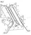
- Fig. 1 is an inventive unit for container-reverse vending machines for the transport and rotation of containers like Bottles and cans shown in a lying position.
- a unit is in a machine for returning containers such as glass bottles, PET bottles and cans.
- the containers are passed through an input port in the case of the machine, which is not shown here, on the Transport unit laid.
- the unit consists of two rollers 1 and 2, the order Axles 3 and 4 are rotatable.
- the rollers 1, 2 are hollow and have in their lateral surface 5 each have an opening 6.
- the rollers 1, 2 each have a conveying device 7, 8 is arranged.
- the conveyors 7, 8 each have a conveyor belt 9, the over pulleys 10 is performed.
- the conveying device 7, 8 is in such a way in the rollers 1,2 arranged that the conveyor belt 9 slightly below the lateral surface. 5 the rollers 5 is in the region of the opening 6.
- a container 11 rests on the conveyor belts 9 of the conveying devices 7, 8, which at an angle of about 120 degrees and thus V-shaped are arranged.
- the drive of the conveyors 7, 8 is advantageously carried out by a common electric motor 12 and a coupling 13.
- a container be transported in its longitudinal direction.
- the pulleys 10 of Conveyors 7, 8 are fixed to supports 14 which are fixed to a in Container automatic reverse vending machines arranged base frame are connected, so that the position of the conveying devices 7, 8 is fixed.
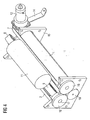
- the rotation rollers 1, 2 are in an engagement with the lateral surface 5 Storage rack 15 rotatably mounted.
- the rotation rollers 1,2 stored between two storage racks 15 to increased stability to achieve the storage of the rollers 1, 2.
- the Rollers 1, 2 at one end face with a ring gear 16 for driving the Rollers 1, 2 provided.
- the storage of rollers 1,2 on the drive side can either also by the storage rack 15 or by a storage take place on the sprocket axis 17.
- the gear 18 will turn driven by a second motor 199.
- the drive motor 19 for driving the rollers 1, 2 in a simple manner outside be attached to the roller. If the rotating rollers 1, 2 in rotation offset, then the lateral surface 5 of the rollers 1, 2 moves over the conveyor belt 9 of the respective conveyor device 7, 8 of time. One on the conveyor belts 9 of the conveyor 7, 8 transported container 11 is through the lateral surface 5 of the roller 1, 2 slightly raised and now stored on the lateral surfaces 5 of the two rollers 1,2. By the same direction Rotary movement of the rollers 1, 2, the container 11 is now rotated, so that above the rollers 1, 2 arranged detector such as a Scanner - not shown here - an attached to the container identification feature such as a barcode or other optical Coding can capture as soon as the feature in the coverage of the Detector comes.
- detector such as a Scanner - not shown here - an attached to the container identification feature such as a barcode or other optical Coding can capture as soon as the feature in the coverage of the Detector comes.
- the container 11 is arranged downstream of one of the transport device Place led. If, on the other hand, it is determined that it is a container 11 for which no pledge is paid out, the container 11 of the Transport device transported in the direction of the input area again.
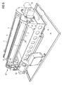
- rollers 1,2 not made of a tube, but consist of individual strip-shaped segments 20 in the longitudinal direction of the rollers 1,2 are arranged and form the lateral surface 5 of the rollers 1,2.
- the Segments 20 are bent in a substantially circular shape so that they are sections form the cylindrical surface 5.
- the segments 20 are on each screwed onto annular support bodies 21 the two ends.
- the lateral surface 5 of Roll 1.2 to provide a coating to the frictional engagement between to influence the rollers 1,2 and the container 11 and running noise to soften the bottle during the rotation.
- the pulleys 10 of the conveyor belts 9 by means of a coupled belt drive 22 to drive and thereby enable a synchronous movement of the conveyor belts 9.
- the pulleys 10 of the conveyor 7,8 are with a Groove 23 provided for the belt 24.
- the belts 24 engage around the Motor 12 arranged deflection plate 25 and are of two other pulleys 26 led.
- a shaft 27 connects the deflection plate 25 with a Deflection pulley 28 for driving the second conveyor 7.
- a coupled belt drive 22 has the advantage over a clutch 13, that it is less susceptible to interference and therefore more suitable for continuous operation is.
- the wheels and belts of the belt drive 22 are also in one Area that is less susceptible to dirt than the intermediate area between the rollers 1,2, since here by the filled with residual fluid bottles soiling can occur due to leaking fluid.
Landscapes
- Mechanical Engineering (AREA)
- Engineering & Computer Science (AREA)
- Physics & Mathematics (AREA)
- General Physics & Mathematics (AREA)
- Sorting Of Articles (AREA)
- Attitude Control For Articles On Conveyors (AREA)
- Processing Of Solid Wastes (AREA)
- Transplanting Machines (AREA)
- Vending Machines For Individual Products (AREA)
- Vehicle Body Suspensions (AREA)
- Forklifts And Lifting Vehicles (AREA)
- Structure Of Belt Conveyors (AREA)
- Surface Acoustic Wave Elements And Circuit Networks Thereof (AREA)
- Body Structure For Vehicles (AREA)
- Turbine Rotor Nozzle Sealing (AREA)
Applications Claiming Priority (5)
| Application Number | Priority Date | Filing Date | Title |
|---|---|---|---|
| DE2003153537 DE10353537B4 (de) | 2003-11-14 | 2003-11-14 | Einheit für Behälter-Rücknahmeautomaten |
| DE10353537 | 2003-11-14 | ||
| DE200410032330 DE102004032330A1 (de) | 2004-07-02 | 2004-07-02 | Behälter-Rücknahmeautomat |
| DE102004032330 | 2004-07-02 | ||
| EP20040017846 EP1531433B1 (fr) | 2003-11-14 | 2004-07-28 | Automate pour conteneurs consignes |
Related Parent Applications (2)
| Application Number | Title | Priority Date | Filing Date |
|---|---|---|---|
| EP20040017846 Division EP1531433B1 (fr) | 2003-11-14 | 2004-07-28 | Automate pour conteneurs consignes |
| EP04017846.9 Division | 2004-07-28 |
Publications (2)
| Publication Number | Publication Date |
|---|---|
| EP1536386A1 true EP1536386A1 (fr) | 2005-06-01 |
| EP1536386B1 EP1536386B1 (fr) | 2006-06-21 |
Family
ID=34436334
Family Applications (2)
| Application Number | Title | Priority Date | Filing Date |
|---|---|---|---|
| EP20040022319 Expired - Lifetime EP1536386B1 (fr) | 2003-11-14 | 2004-07-28 | Appareil de récupération automatique de déchets |
| EP20040017846 Expired - Lifetime EP1531433B1 (fr) | 2003-11-14 | 2004-07-28 | Automate pour conteneurs consignes |
Family Applications After (1)
| Application Number | Title | Priority Date | Filing Date |
|---|---|---|---|
| EP20040017846 Expired - Lifetime EP1531433B1 (fr) | 2003-11-14 | 2004-07-28 | Automate pour conteneurs consignes |
Country Status (9)
| Country | Link |
|---|---|
| US (1) | US7407056B2 (fr) |
| EP (2) | EP1536386B1 (fr) |
| JP (1) | JP2007510607A (fr) |
| AT (2) | ATE339746T1 (fr) |
| DE (2) | DE502004001461D1 (fr) |
| DK (1) | DK1531433T3 (fr) |
| ES (1) | ES2271751T3 (fr) |
| NO (1) | NO335233B1 (fr) |
| WO (1) | WO2005052870A1 (fr) |
Families Citing this family (23)
| Publication number | Priority date | Publication date | Assignee | Title |
|---|---|---|---|---|
| JP2006346634A (ja) * | 2005-06-17 | 2006-12-28 | Sansei Foods Co Ltd | 異形物品の分別方法及びその装置 |
| DE102009037124A1 (de) | 2009-08-11 | 2011-02-17 | Wincor Nixdorf International Gmbh | Vorrichtung und Verfahren zum optischen Abtasten einer maschinenlesbaren Markierung |
| DE102009044537A1 (de) | 2009-11-16 | 2011-05-19 | Wincor Nixdorf International Gmbh | System für eine mobile Warenerfassung und Verfahren hierzu |
| DE102011000025A1 (de) | 2011-01-04 | 2012-07-05 | Wincor Nixdorf International Gmbh | Vorrichtung zum Erfassen von Waren |
| DE102011000087A1 (de) | 2011-01-11 | 2012-07-12 | Wincor Nixdorf International Gmbh | Transporteinheit und Verfahren zum Betrieb derselben |
| DE102011011726A1 (de) * | 2011-02-18 | 2012-08-23 | Envipco Holding N.V. | Einheit für Behälter-Rücknahmeautomaten |
| AU2012205284B2 (en) * | 2011-08-16 | 2015-07-23 | Maf Agrobotic | Singulator |
| CN103420132A (zh) * | 2012-05-15 | 2013-12-04 | 上海沛愉机械制造有限公司 | 一种理瓶机瓶子方位理正方法 |
| EP2727860A1 (fr) * | 2012-10-30 | 2014-05-07 | Tomra Systems ASA | Module d'accueil de module de transporteur pour distributeur automatique inverse |
| KR200480081Y1 (ko) | 2014-07-08 | 2016-04-12 | 권익삼 | 농산물 선별기 |
| CN104443943B (zh) * | 2014-10-14 | 2017-03-15 | 深圳市利恩信息技术有限公司 | 一种饮料瓶回收装置 |
| CN104528343B (zh) * | 2014-12-10 | 2017-12-19 | 浙江群石工业设计有限公司 | 一种圆头端轴类工件调头装置 |
| JP6690640B2 (ja) * | 2015-04-24 | 2020-04-28 | ニプロ株式会社 | 医療用ガラス容器の製造方法及び回転装置を備えたファイアブラスト装置 |
| EP3159856B1 (fr) * | 2015-10-21 | 2022-01-26 | Wincor Nixdorf International GmbH | Unité d'introduction pour un automate de reprise pour bouteilles consignées et automate de reprise pour bouteilles consignées |
| IT201700044060A1 (it) * | 2017-04-21 | 2018-10-21 | Laservideo S R L | Distributore automatico di pacchetti |
| CN107215672A (zh) * | 2017-06-28 | 2017-09-29 | 深圳市研创精密设备有限公司 | 一种插片机的玻璃输送机构 |
| CN109896224B (zh) * | 2017-12-11 | 2024-03-12 | 江苏中天华宇智能科技有限公司 | 光纤盘的输送系统 |
| CN109176567B (zh) * | 2018-09-27 | 2024-09-24 | 湖北汉唐智能科技股份有限公司 | 齿轮搬运检测助力机械臂 |
| US10494179B1 (en) * | 2018-10-10 | 2019-12-03 | Amazon Technologies, Inc. | Systems having V-shaped conveyors and methods of using the same |
| US11040831B2 (en) * | 2018-10-31 | 2021-06-22 | Setpoint Systems, Inc. | Dual conveyor sorting system |
| CN114524247B (zh) * | 2022-02-23 | 2024-05-31 | 广西禾乐生态农业开发有限公司 | 一种含射频识别技术的分拣作业工作台 |
| CN117875342B (zh) * | 2024-03-12 | 2024-05-10 | 山东软服自动识别技术有限公司 | 一种用于产品标识微识别的设备 |
| CN118651816B (zh) * | 2024-08-21 | 2025-02-07 | 河北博嘉农业有限公司 | 异形瓶分离设备 |
Citations (4)
| Publication number | Priority date | Publication date | Assignee | Title |
|---|---|---|---|---|
| US4151908A (en) * | 1976-12-07 | 1979-05-01 | Ugo Brusa | Device for displacing elongated bodies transversely to their axes |
| US5934440A (en) * | 1996-07-12 | 1999-08-10 | Tomra Systems Asa | Conveyor device for inspecting containers and transporting them to selected destinations |
| EP1167247A1 (fr) * | 2000-06-16 | 2002-01-02 | Bevesys Oy | Ensemble de convoyage |
| US20030187546A1 (en) * | 2000-08-04 | 2003-10-02 | Kristian Holmen | Device for handling liquid containers |
Family Cites Families (2)
| Publication number | Priority date | Publication date | Assignee | Title |
|---|---|---|---|---|
| DE10055208B4 (de) | 2000-11-07 | 2004-01-22 | Prokent Ag I.Ins. | Einheit für Behälter-Rücknahmeautomaten |
| WO2002039393A2 (fr) * | 2000-11-07 | 2002-05-16 | Prokent Ag | Unite destinee a des systemes automatiques de reprise de contenants |
-
2004
- 2004-07-28 EP EP20040022319 patent/EP1536386B1/fr not_active Expired - Lifetime
- 2004-07-28 AT AT04017846T patent/ATE339746T1/de not_active IP Right Cessation
- 2004-07-28 EP EP20040017846 patent/EP1531433B1/fr not_active Expired - Lifetime
- 2004-07-28 DE DE200450001461 patent/DE502004001461D1/de not_active Expired - Lifetime
- 2004-07-28 AT AT04022319T patent/ATE331262T1/de active
- 2004-07-28 DE DE200450000823 patent/DE502004000823D1/de not_active Expired - Lifetime
- 2004-07-28 ES ES04017846T patent/ES2271751T3/es not_active Expired - Lifetime
- 2004-07-28 DK DK04017846T patent/DK1531433T3/da active
- 2004-09-20 JP JP2006538673A patent/JP2007510607A/ja not_active Withdrawn
- 2004-09-20 US US10/579,116 patent/US7407056B2/en not_active Expired - Lifetime
- 2004-09-20 WO PCT/EP2004/010541 patent/WO2005052870A1/fr not_active Ceased
-
2006
- 2006-06-13 NO NO20062748A patent/NO335233B1/no not_active IP Right Cessation
Patent Citations (4)
| Publication number | Priority date | Publication date | Assignee | Title |
|---|---|---|---|---|
| US4151908A (en) * | 1976-12-07 | 1979-05-01 | Ugo Brusa | Device for displacing elongated bodies transversely to their axes |
| US5934440A (en) * | 1996-07-12 | 1999-08-10 | Tomra Systems Asa | Conveyor device for inspecting containers and transporting them to selected destinations |
| EP1167247A1 (fr) * | 2000-06-16 | 2002-01-02 | Bevesys Oy | Ensemble de convoyage |
| US20030187546A1 (en) * | 2000-08-04 | 2003-10-02 | Kristian Holmen | Device for handling liquid containers |
Also Published As
| Publication number | Publication date |
|---|---|
| ATE331262T1 (de) | 2006-07-15 |
| NO20062748L (no) | 2006-06-13 |
| US7407056B2 (en) | 2008-08-05 |
| DE502004000823D1 (de) | 2006-08-03 |
| NO335233B1 (no) | 2014-10-27 |
| JP2007510607A (ja) | 2007-04-26 |
| US20070080045A1 (en) | 2007-04-12 |
| DE502004001461D1 (de) | 2006-10-26 |
| EP1531433A1 (fr) | 2005-05-18 |
| WO2005052870A1 (fr) | 2005-06-09 |
| DK1531433T3 (da) | 2007-01-02 |
| EP1536386B1 (fr) | 2006-06-21 |
| ES2271751T3 (es) | 2007-04-16 |
| ATE339746T1 (de) | 2006-10-15 |
| EP1531433B1 (fr) | 2006-09-13 |
Similar Documents
| Publication | Publication Date | Title |
|---|---|---|
| EP1536386B1 (fr) | Appareil de récupération automatique de déchets | |
| DE69511811T2 (de) | Förderanlage | |
| DE69619009T3 (de) | PKW-Transportanlage | |
| DE69006132T2 (de) | Indexiergerät mit rotierender Bewegung. | |
| DE2262556A1 (de) | Vorrichtung zur pruefung von ampullen | |
| DE2261463C2 (de) | Vorrichtung zum schrittweisen Überführen einer Serie von Behältern zwischen einer Anzahl von Stationen | |
| DE60100297T2 (de) | Anlage zum Sortieren und Überführen von Glasscheiben | |
| DE20002411U1 (de) | Vorrichtung zum Ablenken von Gegenständen, insbesondere Behältern, von einer Bewegungsbahn | |
| WO2013030252A1 (fr) | Dispositif de retournement pour objets d'identification | |
| EP1892207A2 (fr) | Dispositif destiné à la répartition et/ou le trie de rouleaux de matériau et leur transmission et un procédé de transport de rouleaux de matériau | |
| DE10353537B4 (de) | Einheit für Behälter-Rücknahmeautomaten | |
| DE3836363A1 (de) | Verfahren und vorrichtung zum ueberfuehren von einbahnig zugefuehrten gegenstaenden auf mehrere abfoerderbahnen | |
| CH692662A5 (de) | Vorrichtung an einer Spinnereimaschine, z.B. Karde, Strecke, zum Fördern und Bereitstellen von Spinnkannen. | |
| EP0857671B1 (fr) | Dispositif pour retourner des corps de boítes | |
| EP2676251A1 (fr) | Unité pour machines automatiques de récupération de contenants | |
| DE3922934C2 (fr) | ||
| DE19807229A1 (de) | Rollenantriebseinheit und Ladesystem mit Sensoren und einer Steuerlogik, insbesondere zum motorgetriebenen Anheben und Absenken der Antriebsrollen von Rollenantriebseinheiten | |
| DE10055206A1 (de) | Einheit für Behälter-Rücknahmeautomaten | |
| DE2538169C2 (de) | Vorrichtung zum Transport von Werkstücken zwischen einer Werkstückladestation und einer Werkstückentladestation einschließlich des Rückhubes | |
| WO2019238314A1 (fr) | Dispositif pour transporter des récipients dans une machine de nettoyage | |
| DE2552211B2 (de) | Vorrichtung zum Transportieren von Gefäßen | |
| DE102004032330A1 (de) | Behälter-Rücknahmeautomat | |
| DE3709722C2 (fr) | ||
| DE3922522A1 (de) | Verfahren und einrichtung zur automatischen streckenbandversorgung eines oe-spinnspulautomaten | |
| DE4142785A1 (de) | Vorrichtung zur verwendung bei einem verschlussmagazin zum einfuehren von kronenkorken oder dergleichen verschluesse in einen verschlusskanal sowie verschlussmagazin |
Legal Events
| Date | Code | Title | Description |
|---|---|---|---|
| PUAI | Public reference made under article 153(3) epc to a published international application that has entered the european phase |
Free format text: ORIGINAL CODE: 0009012 |
|
| 17P | Request for examination filed |
Effective date: 20040920 |
|
| AC | Divisional application: reference to earlier application |
Ref document number: 1531433 Country of ref document: EP Kind code of ref document: P |
|
| AK | Designated contracting states |
Kind code of ref document: A1 Designated state(s): AT BE BG CH CY CZ DE DK EE ES FI FR GB GR HU IE IT LI LU MC NL PL PT RO SE SI SK TR |
|
| AX | Request for extension of the european patent |
Extension state: AL HR LT LV MK |
|
| GRAP | Despatch of communication of intention to grant a patent |
Free format text: ORIGINAL CODE: EPIDOSNIGR1 |
|
| AKX | Designation fees paid |
Designated state(s): AT BE BG CH CY CZ DE DK EE ES FI FR GB GR HU IE IT LI LU MC NL PL PT RO SE SI SK TR |
|
| GRAS | Grant fee paid |
Free format text: ORIGINAL CODE: EPIDOSNIGR3 |
|
| GRAA | (expected) grant |
Free format text: ORIGINAL CODE: 0009210 |
|
| AC | Divisional application: reference to earlier application |
Ref document number: 1531433 Country of ref document: EP Kind code of ref document: P |
|
| AK | Designated contracting states |
Kind code of ref document: B1 Designated state(s): AT BE BG CH CY CZ DE DK EE ES FI FR GB GR HU IE IT LI LU MC NL PL PT RO SE SI SK TR |
|
| PG25 | Lapsed in a contracting state [announced via postgrant information from national office to epo] |
Ref country code: IT Free format text: LAPSE BECAUSE OF FAILURE TO SUBMIT A TRANSLATION OF THE DESCRIPTION OR TO PAY THE FEE WITHIN THE PRESCRIBED TIME-LIMIT;WARNING: LAPSES OF ITALIAN PATENTS WITH EFFECTIVE DATE BEFORE 2007 MAY HAVE OCCURRED AT ANY TIME BEFORE 2007. THE CORRECT EFFECTIVE DATE MAY BE DIFFERENT FROM THE ONE RECORDED. Effective date: 20060621 Ref country code: GB Free format text: LAPSE BECAUSE OF FAILURE TO SUBMIT A TRANSLATION OF THE DESCRIPTION OR TO PAY THE FEE WITHIN THE PRESCRIBED TIME-LIMIT Effective date: 20060621 Ref country code: SK Free format text: LAPSE BECAUSE OF FAILURE TO SUBMIT A TRANSLATION OF THE DESCRIPTION OR TO PAY THE FEE WITHIN THE PRESCRIBED TIME-LIMIT Effective date: 20060621 Ref country code: IE Free format text: LAPSE BECAUSE OF FAILURE TO SUBMIT A TRANSLATION OF THE DESCRIPTION OR TO PAY THE FEE WITHIN THE PRESCRIBED TIME-LIMIT Effective date: 20060621 Ref country code: SI Free format text: LAPSE BECAUSE OF FAILURE TO SUBMIT A TRANSLATION OF THE DESCRIPTION OR TO PAY THE FEE WITHIN THE PRESCRIBED TIME-LIMIT Effective date: 20060621 Ref country code: CZ Free format text: LAPSE BECAUSE OF FAILURE TO SUBMIT A TRANSLATION OF THE DESCRIPTION OR TO PAY THE FEE WITHIN THE PRESCRIBED TIME-LIMIT Effective date: 20060621 Ref country code: NL Free format text: LAPSE BECAUSE OF FAILURE TO SUBMIT A TRANSLATION OF THE DESCRIPTION OR TO PAY THE FEE WITHIN THE PRESCRIBED TIME-LIMIT Effective date: 20060621 Ref country code: PL Free format text: LAPSE BECAUSE OF FAILURE TO SUBMIT A TRANSLATION OF THE DESCRIPTION OR TO PAY THE FEE WITHIN THE PRESCRIBED TIME-LIMIT Effective date: 20060621 Ref country code: RO Free format text: LAPSE BECAUSE OF FAILURE TO SUBMIT A TRANSLATION OF THE DESCRIPTION OR TO PAY THE FEE WITHIN THE PRESCRIBED TIME-LIMIT Effective date: 20060621 |
|
| REG | Reference to a national code |
Ref country code: GB Ref legal event code: FG4D Free format text: NOT ENGLISH |
|
| REG | Reference to a national code |
Ref country code: CH Ref legal event code: EP |
|
| REG | Reference to a national code |
Ref country code: IE Ref legal event code: FG4D Free format text: LANGUAGE OF EP DOCUMENT: GERMAN |
|
| PG25 | Lapsed in a contracting state [announced via postgrant information from national office to epo] |
Ref country code: BE Free format text: LAPSE BECAUSE OF NON-PAYMENT OF DUE FEES Effective date: 20060731 Ref country code: MC Free format text: LAPSE BECAUSE OF NON-PAYMENT OF DUE FEES Effective date: 20060731 |
|
| REF | Corresponds to: |
Ref document number: 502004000823 Country of ref document: DE Date of ref document: 20060803 Kind code of ref document: P |
|
| PG25 | Lapsed in a contracting state [announced via postgrant information from national office to epo] |
Ref country code: DK Free format text: LAPSE BECAUSE OF FAILURE TO SUBMIT A TRANSLATION OF THE DESCRIPTION OR TO PAY THE FEE WITHIN THE PRESCRIBED TIME-LIMIT Effective date: 20060921 |
|
| PG25 | Lapsed in a contracting state [announced via postgrant information from national office to epo] |
Ref country code: ES Free format text: LAPSE BECAUSE OF FAILURE TO SUBMIT A TRANSLATION OF THE DESCRIPTION OR TO PAY THE FEE WITHIN THE PRESCRIBED TIME-LIMIT Effective date: 20061002 |
|
| REG | Reference to a national code |
Ref country code: SE Ref legal event code: TRGR |
|
| PG25 | Lapsed in a contracting state [announced via postgrant information from national office to epo] |
Ref country code: PT Free format text: LAPSE BECAUSE OF FAILURE TO SUBMIT A TRANSLATION OF THE DESCRIPTION OR TO PAY THE FEE WITHIN THE PRESCRIBED TIME-LIMIT Effective date: 20061121 |
|
| NLV1 | Nl: lapsed or annulled due to failure to fulfill the requirements of art. 29p and 29m of the patents act | ||
| GBV | Gb: ep patent (uk) treated as always having been void in accordance with gb section 77(7)/1977 [no translation filed] |
Effective date: 20060621 |
|
| REG | Reference to a national code |
Ref country code: IE Ref legal event code: FD4D |
|
| PLBE | No opposition filed within time limit |
Free format text: ORIGINAL CODE: 0009261 |
|
| STAA | Information on the status of an ep patent application or granted ep patent |
Free format text: STATUS: NO OPPOSITION FILED WITHIN TIME LIMIT |
|
| EN | Fr: translation not filed | ||
| 26N | No opposition filed |
Effective date: 20070322 |
|
| BERE | Be: lapsed |
Owner name: WINCOR NIXDORF INTERNATIONAL G.M.B.H. Effective date: 20060731 |
|
| PG25 | Lapsed in a contracting state [announced via postgrant information from national office to epo] |
Ref country code: FR Free format text: LAPSE BECAUSE OF FAILURE TO SUBMIT A TRANSLATION OF THE DESCRIPTION OR TO PAY THE FEE WITHIN THE PRESCRIBED TIME-LIMIT Effective date: 20070504 Ref country code: GR Free format text: LAPSE BECAUSE OF FAILURE TO SUBMIT A TRANSLATION OF THE DESCRIPTION OR TO PAY THE FEE WITHIN THE PRESCRIBED TIME-LIMIT Effective date: 20060922 |
|
| PG25 | Lapsed in a contracting state [announced via postgrant information from national office to epo] |
Ref country code: BG Free format text: LAPSE BECAUSE OF FAILURE TO SUBMIT A TRANSLATION OF THE DESCRIPTION OR TO PAY THE FEE WITHIN THE PRESCRIBED TIME-LIMIT Effective date: 20060921 Ref country code: FI Free format text: LAPSE BECAUSE OF FAILURE TO SUBMIT A TRANSLATION OF THE DESCRIPTION OR TO PAY THE FEE WITHIN THE PRESCRIBED TIME-LIMIT Effective date: 20060621 Ref country code: EE Free format text: LAPSE BECAUSE OF FAILURE TO SUBMIT A TRANSLATION OF THE DESCRIPTION OR TO PAY THE FEE WITHIN THE PRESCRIBED TIME-LIMIT Effective date: 20060621 |
|
| PG25 | Lapsed in a contracting state [announced via postgrant information from national office to epo] |
Ref country code: TR Free format text: LAPSE BECAUSE OF FAILURE TO SUBMIT A TRANSLATION OF THE DESCRIPTION OR TO PAY THE FEE WITHIN THE PRESCRIBED TIME-LIMIT Effective date: 20060621 Ref country code: HU Free format text: LAPSE BECAUSE OF FAILURE TO SUBMIT A TRANSLATION OF THE DESCRIPTION OR TO PAY THE FEE WITHIN THE PRESCRIBED TIME-LIMIT Effective date: 20061222 Ref country code: LU Free format text: LAPSE BECAUSE OF NON-PAYMENT OF DUE FEES Effective date: 20060728 |
|
| PG25 | Lapsed in a contracting state [announced via postgrant information from national office to epo] |
Ref country code: FR Free format text: LAPSE BECAUSE OF FAILURE TO SUBMIT A TRANSLATION OF THE DESCRIPTION OR TO PAY THE FEE WITHIN THE PRESCRIBED TIME-LIMIT Effective date: 20060731 |
|
| PG25 | Lapsed in a contracting state [announced via postgrant information from national office to epo] |
Ref country code: FR Free format text: LAPSE BECAUSE OF FAILURE TO SUBMIT A TRANSLATION OF THE DESCRIPTION OR TO PAY THE FEE WITHIN THE PRESCRIBED TIME-LIMIT Effective date: 20060621 Ref country code: CY Free format text: LAPSE BECAUSE OF FAILURE TO SUBMIT A TRANSLATION OF THE DESCRIPTION OR TO PAY THE FEE WITHIN THE PRESCRIBED TIME-LIMIT Effective date: 20060621 |
|
| REG | Reference to a national code |
Ref country code: CH Ref legal event code: PL |
|
| PG25 | Lapsed in a contracting state [announced via postgrant information from national office to epo] |
Ref country code: CH Free format text: LAPSE BECAUSE OF NON-PAYMENT OF DUE FEES Effective date: 20080731 Ref country code: LI Free format text: LAPSE BECAUSE OF NON-PAYMENT OF DUE FEES Effective date: 20080731 |
|
| PGFP | Annual fee paid to national office [announced via postgrant information from national office to epo] |
Ref country code: SE Payment date: 20100723 Year of fee payment: 7 |
|
| REG | Reference to a national code |
Ref country code: SE Ref legal event code: EUG |
|
| PG25 | Lapsed in a contracting state [announced via postgrant information from national office to epo] |
Ref country code: SE Free format text: LAPSE BECAUSE OF NON-PAYMENT OF DUE FEES Effective date: 20110729 |
|
| REG | Reference to a national code |
Ref country code: DE Ref legal event code: R082 Ref document number: 502004000823 Country of ref document: DE Representative=s name: SCHAUMBURG & PARTNER PATENTANWAELTE GBR, DE Ref country code: DE Ref legal event code: R082 Ref document number: 502004000823 Country of ref document: DE Representative=s name: SCHAUMBURG UND PARTNER PATENTANWAELTE MBB, DE |
|
| PGFP | Annual fee paid to national office [announced via postgrant information from national office to epo] |
Ref country code: AT Payment date: 20190621 Year of fee payment: 16 |
|
| REG | Reference to a national code |
Ref country code: AT Ref legal event code: MM01 Ref document number: 331262 Country of ref document: AT Kind code of ref document: T Effective date: 20200728 |
|
| PG25 | Lapsed in a contracting state [announced via postgrant information from national office to epo] |
Ref country code: AT Free format text: LAPSE BECAUSE OF NON-PAYMENT OF DUE FEES Effective date: 20200728 |
|
| REG | Reference to a national code |
Ref country code: DE Ref legal event code: R082 Ref document number: 502004000823 Country of ref document: DE Representative=s name: VIERING, JENTSCHURA & PARTNER MBB PATENT- UND , DE |
|
| PGFP | Annual fee paid to national office [announced via postgrant information from national office to epo] |
Ref country code: DE Payment date: 20220422 Year of fee payment: 19 |
|
| REG | Reference to a national code |
Ref country code: DE Ref legal event code: R119 Ref document number: 502004000823 Country of ref document: DE |
|
| PG25 | Lapsed in a contracting state [announced via postgrant information from national office to epo] |
Ref country code: DE Free format text: LAPSE BECAUSE OF NON-PAYMENT OF DUE FEES Effective date: 20240201 |