EP1536455A1 - Vakuumschleusenanordnung - Google Patents
Vakuumschleusenanordnung Download PDFInfo
- Publication number
- EP1536455A1 EP1536455A1 EP04027993A EP04027993A EP1536455A1 EP 1536455 A1 EP1536455 A1 EP 1536455A1 EP 04027993 A EP04027993 A EP 04027993A EP 04027993 A EP04027993 A EP 04027993A EP 1536455 A1 EP1536455 A1 EP 1536455A1
- Authority
- EP
- European Patent Office
- Prior art keywords
- lock
- vacuum
- substrate
- substrate holder
- high vacuum
- Prior art date
- Legal status (The legal status is an assumption and is not a legal conclusion. Google has not performed a legal analysis and makes no representation as to the accuracy of the status listed.)
- Granted
Links
Images

Classifications
-
- C—CHEMISTRY; METALLURGY
- C23—COATING METALLIC MATERIAL; COATING MATERIAL WITH METALLIC MATERIAL; CHEMICAL SURFACE TREATMENT; DIFFUSION TREATMENT OF METALLIC MATERIAL; COATING BY VACUUM EVAPORATION, BY SPUTTERING, BY ION IMPLANTATION OR BY CHEMICAL VAPOUR DEPOSITION, IN GENERAL; INHIBITING CORROSION OF METALLIC MATERIAL OR INCRUSTATION IN GENERAL
- C23C—COATING METALLIC MATERIAL; COATING MATERIAL WITH METALLIC MATERIAL; SURFACE TREATMENT OF METALLIC MATERIAL BY DIFFUSION INTO THE SURFACE, BY CHEMICAL CONVERSION OR SUBSTITUTION; COATING BY VACUUM EVAPORATION, BY SPUTTERING, BY ION IMPLANTATION OR BY CHEMICAL VAPOUR DEPOSITION, IN GENERAL
- C23C14/00—Coating by vacuum evaporation, by sputtering or by ion implantation of the coating forming material
- C23C14/22—Coating by vacuum evaporation, by sputtering or by ion implantation of the coating forming material characterised by the process of coating
- C23C14/56—Apparatus specially adapted for continuous coating; Arrangements for maintaining the vacuum, e.g. vacuum locks
- C23C14/564—Means for minimising impurities in the coating chamber such as dust, moisture, residual gases
- C23C14/566—Means for minimising impurities in the coating chamber such as dust, moisture, residual gases using a load-lock chamber
-
- H—ELECTRICITY
- H10—SEMICONDUCTOR DEVICES; ELECTRIC SOLID-STATE DEVICES NOT OTHERWISE PROVIDED FOR
- H10P—GENERIC PROCESSES OR APPARATUS FOR THE MANUFACTURE OR TREATMENT OF DEVICES COVERED BY CLASS H10
- H10P72/00—Handling or holding of wafers, substrates or devices during manufacture or treatment thereof
- H10P72/30—Handling or holding of wafers, substrates or devices during manufacture or treatment thereof for conveying, e.g. between different workstations
- H10P72/33—Handling or holding of wafers, substrates or devices during manufacture or treatment thereof for conveying, e.g. between different workstations into and out of processing chamber
- H10P72/3308—Vertical transfer of a single workpiece
Definitions
- the invention relates to a vacuum lock arrangement with a lock and a Chamber for high vacuum, which can be connected to the lock.
- the invention relates to a vacuum lock arrangement consisting of a Sluice, a transport chamber and two process chambers, for example, for a Both sides treatment of substrates is suitable, and a transport method by means of the arrangement according to the invention is carried out. At least one substrate is over the Lock placed in a substrate holder, which is arranged on a substrate carrier and is transported through the transport chamber to the process chambers, wherein in the Transport chamber and in the Prozeßkammem a high vacuum exists or maintained becomes.
- DE-C1-198 06 282 discloses a device with a lock, a transport chamber and a Process chamber in which a substrate via a lock on a substrate carrier, as Hubschwenkja is formed, is stored and through the transport chamber for Process chamber is transported. After a pre-vacuum has been generated in the lock, the substrate carrier is lowered to transport the substrate into the process chamber, wherein the pre-vacuum over the transport space with the high vacuum of the process chamber in Connection comes; The occurring pressure increase can the process in the Negatively influence the process chamber.
- the invention is based on the object, a vacuum lock arrangement and a Transport method to provide by means of this arrangement, wherein a pressure surge or an increase in pressure in at least one high-vacuum chamber in another Evacuation of a preceding Vorvakuumhunt is reliably avoided.
- the invention is based on the following basic ideas.
- the substrate holders are e.g. via tension springs with the substrate carrier coupled.
- the lock has an outer first and an inner second Lock cover on. The first lock cover closes the lock to the outside, and the second lock cover closes together with a respective substrate holder the Transport space and the Prozeßkammem against the lock when a substrate introduced becomes.
- the second lock lid pushes the substrate holder against the force of the springs, holding the substrate holder in the substrate carrier, against the opening of the lock.
- the second Sluice cover is divided into two parts, with a first part via springs, preferably compression springs connected to a second part, so that the springs in the unloaded state between Keep the two parts open an annular high-vacuum channel.
- the springs i. when the second lock cover the substrate holder against the opening of the Lock presses, the high vacuum channel is closed.
- the lock After inserting at least one Substrate in the substrate holder at the lock is the lock through the first Closed lock and a vent Vorvakuumpumpenkanal by a Pre-vacuum pump evacuated to pre-vacuum.
- the second lock cover from the lock wegrion so that the substrate holder with the substrate to be treated, for example by the force of the spring connecting it to the substrate carrier, or if the chambers are horizontally disposed, retracted only by gravity on the substrate carrier becomes.
- About the still open high-vacuum channel are now the process chambers, the Transport chamber and the lock connected to the high vacuum pump and a suitable high vacuum can be maintained.
- a treated substrate from the Process chambers can then to the lock and vice versa the substrate to be treated to the Process chamber to be transported through the turntable.
- the removal of the treated Substrate takes place after the second lock cover the substrate holder to the Lock opening has been pressed, the high-vacuum channel is closed and the lock ventilated by a valve.
- the advantage of the invention lies in more stable process conditions and an improvement of Quality in the treatment of, for example, CDs, DVDs, optical lenses and Eyeglass lenses, for example in sensitive coating processes.
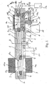
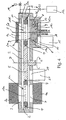
- Figures 1 to 4 show cross-sections of an embodiment of the vacuum lock arrangement according to the invention, which is preferably provided for the two-sided treatment of substrates.
- the system according to the invention comprises a transport chamber 2 between a lock 1 and two mutually opposite process chambers 3 and 4, at whose openings process devices 3a and 4a, eg sputtering devices, ion guns or CVD coating devices are arranged, which are arranged horizontally in the figures , but also differently, for example vertically standing, can be arranged.
- the transport chamber 2 designed as a turntable or swivel arm substrate carrier 5 is arranged, which carries a first and a second substrate holder 6a and 6b and in the direction of arrow C about the axis D between the lock 1 and the process chambers 3 and 4 is pivotable. In the context of the invention, a movement along the axis D is not required.
- the substrate holder 6a, 6b are arranged by means of tension springs 7 on the substrate carrier 5 against this movable, wherein, when the springs 7 are not loaded, they are at the same level as the substrate carrier.
- the transport chamber 2 has a further high-vacuum pump connection 19 with a high-vacuum pump 20.
- the lock 1 has an outer first lock cover 1a and an inner second lock cover 16.
- the inner second lock cover 1b is relative to the lock 1 along the axis E in the direction of arrow A and B by a piston rod 18 slidably.
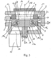
- the second lock cover 1b consists of two parts 1b 1 and 1b 2 , which are interconnected by compression springs 8 and form an annular high-vacuum channel 9 with unloaded springs between them.
- a high vacuum pump connection 10 is arranged, which communicates with the high vacuum passage 9.
- a high vacuum pump 15 is connected, which is preferably a turbomolecular pump.
- the lock 1 has a ventilation and pre-vacuum pump channel 11 to ventilate the lock 1 either via a valve 14 or to evacuate with a closed valve 14 via an open valve 16 through a backing pump 12.
- the substrate holder 6b is sealed by vacuum seals (not shown) in the region of the lock against the wall 2a of the transport chamber 2 and the part 1b 1 .
- Vacuum seals (not shown) are also disposed between the first part 1b 1 and the second part 1b 2 of the inner lock cover to reliably close the high vacuum passage 9 when the lock 1 is opened to the outside or pre-vacuum is generated.
- the two process chambers with respect to the axis of rotation D in the azimuth direction can also be arranged offset from one another on both sides of the transport device 5 if more than two substrate holders are provided.
- the lock 1 is thus closed against the transport chamber 2, and thus against the process chambers 3 and 4, and against the space 13 behind the second lock cover 1 b with the high vacuum pump connection 10.
- the first substrate holder 6a is located between the process chambers 3 and 4, so that the substrate 17a can be treated on one side and preferably simultaneously or sequentially from both sides. In this way, for example, CDs, DVDs, optical lenses or spectacle lenses can be coated or cleaned, for example by sputter etching.
- the lock 1 is closed with the valve 14 and valve 16 open via the channel 11 through the backing pump 12 to a pre-vacuum of e.g. 0.1 to 3 mbar, preferably 1 mbar evacuated. This condition is shown in FIG.
- the second lock cover 1b with Help the piston rod 18 in the direction of arrow A by a certain distance further down moved, but preferably not on the floor 13a of the space 13 behind (in the Drawing below) placed on the inner lock cover, the high vacuum channel. 9 opened by the pressure force of the springs 8 and in conjunction with the High vacuum connection 10 remains.
- the second substrate holder 6b is released and by the force of the springs 7 in the Retracted position shown in Fig. 4 in the substrate carrier 5.
- the second substrate carrier 6b becomes the substrate 17b to be treated Process chambers 3 and 4 and the first substrate holder 6a with the treated substrate 17a for Lock 1 by a rotational movement of the substrate carrier 5 in the direction of arrow C about the axis D transported.
- the transport chamber 2 and the lock 1 is through the high vacuum passage 9 and the high vacuum pump port 10 through the High vacuum pump 15 and the high vacuum pump port 19 through the High vacuum pump 20 maintained a high vacuum. This state is in FIG. 4 shown.
- the substrate carrier (turntable) 5 may have more than two substrate holders 6a, 6b, for example five with each 72 ° distance on the circumference, in the same way as the first two substrate holder 6a and 6b connected via tension springs to the substrate carrier 5 could be.
- the substrate holder may be constructed to have a plurality of Can carry substrates, so that several substrates simultaneously in the first and second Process space 3 or 4 can be treated.
Landscapes
- Chemical & Material Sciences (AREA)
- Chemical Kinetics & Catalysis (AREA)
- Engineering & Computer Science (AREA)
- Materials Engineering (AREA)
- Mechanical Engineering (AREA)
- Metallurgy (AREA)
- Organic Chemistry (AREA)
- Physical Vapour Deposition (AREA)
- Exposure Of Semiconductors, Excluding Electron Or Ion Beam Exposure (AREA)
- Container, Conveyance, Adherence, Positioning, Of Wafer (AREA)
- Compressors, Vaccum Pumps And Other Relevant Systems (AREA)
- External Artificial Organs (AREA)
- Superconductors And Manufacturing Methods Therefor (AREA)
- Respiratory Apparatuses And Protective Means (AREA)
Abstract
Description
- Figur 1
- einen Querschnitt durch eine Ausführungsform der erfindungsgemäßen Anordnung, wobei die Verbindung zwischen der Schleuse und der Transportkammer sowie den Prozeßkammern geschlossen ist,
- Figur 2
- die Ausführungsform gemäß Figur 1, wobei eine Verbindung zwischen der Schleuse und einer Hochvakuumpumpe hergestellt ist,
- Figur 3
- einen vergrößerten Ausschnitt aus Figur 2, und
- Figur 4
- die Ausführungsform gemäß Figur 1, wobei eine Verbindung zwischen den Prozeßkammern, der Transportkammer, der Schleuse und der Hochvakuumpumpe hergestellt ist.
Claims (19)
- Vakuumschleusenanordnung mit:(a) einer Schleuse (1) mit einem Belüftungs- Vakuumpumpenanschluß (11);(b) einer Hochvakuumkammer (2); wobei(c) die Schleuse (1) einen äußeren Schleusendeckel (1a) und einen inneren Schleusendeckel (1b) zum Verschließen der Schleuse (1) gegen die Hochvakuumkammer (2) aufweist,
dadurch gekennzeichnet, daß(d) der innere Schleusendeckel (1b) ein erstes Teil (1b1) und ein zweites Teil (1b2) aufweist, die durch Federn (8) miteinander verbunden sind und bei unbelasteten Federn (8) zwischen sich einen ersten Hochvakuumkanal (9) ausbilden, der die Schleuse (1) mit einem ersten Hochvakuumsanschluß (10) verbindet. - Vakuumschleusenanordnung nach Anspruch 1, wobei die Hochvakuumkammer als Transportkammer (2) ausgebildet ist, in der eine Transporteinrichtung (5) zum Transportieren mindestens eines Substrats (17a, 17b) angeordnet ist.
- Vakuumschleusenanordnung nach Anspruch 2, wobei die Transporteinrichtung ein als Drehteller ausgebildeter Substratträger (5) ist und mindestens ein erster und ein zweiter Substrathalter (6a bzw. 6b) vorgesehen sind, die bewegbar mit dem Substratträger (5) verbunden sind.
- Vakuumschleusenanordnung nach Anspruch 3, wobei der Substrathalter (6a, 6b) gegen die Öffnung (1c) der Schleuse (1) durch den inneren Schleusendeckel mittels einer Hubstange (18) drückbar ist, so daß der Substrathalter (6a, 6b) und der innere Schleusendeckel (1b) die Transportkammer (2) gegen die Schleuse (1) verschließen.
- Vakuumanordnung nach Anspruch 4, wobei mit der Transportkammer (2) mindestens eine erste Prozeßkammer (3) für Hochvakuum verbunden ist.
- Vakuumschleusenanordnung nach Anspruch 5, wobei eine zweite Prozeßkammer (4) der ersten Prozeßkammer (3) gegenüberliegend auf der anderen Seite der Transporteinrichtung (5) angeordnet ist.
- Vakuumschleuseneinrichtung nach Anspruch 5, wobei eine zweite Prozeßkammer auf der anderen Seite der Transporteinrichtung (5) und bezüglich der Drehachse D in Azimutrichtung versetzt zur ersten Prozeßkammer (3) angeordnet ist.
- Vakuumschleusenanordnung nach Anspruch 5, 6 oder 7, wobei der Substratträger (5) um eine Schwenkachse (D) in Schwenkrichtung (C) zwischen der Schleuse (1) und der mindestens einen Prozeßkammer (3) hin und her bewegbar ist.
- Vakuumschleusenanordnung nach einem der Ansprüche 1 bis 8, wobei der erste Hochvakuumpumpenanschluß (10) in Richtung (A) hinter dem zweiten Schleusendeckel (1b) angeordnet ist.
- Vakuumschleusenanordnung nach einem der Ansprüche 7 bis 9, wobei die Transportkammer (2) einen zweiten Hochvakuumpumpenanschluß (19) mit einer zweiten Hochvakuumpumpe (20) aufweist.
- Vakuumschleusenanordnung nach einem der Ansprüche 3 bis 10, wobei die ersten und zweiten Substrathalter (6a bzw. 6b) durch Federn (7) mit dem Substratträger (5) verbunden sind.
- Vakuumschleusenanordnung nach einem der Ansprüche 1 bis 11, wobei die Federn (7, 8) vorgespannte Druckfedern oder Zugfedern sind, die vorzugsweise durch Membranfedern geführt werden.
- Vakuumschleusenanordnung nach einem der Ansprüche 1 bis 12, wobei die Hochvakuumpumpenanschlüsse (10, 19) an Turbomolekularpumpen (15 bzw. 20) angeschlossen sind.
- Verfahren zum Transportieren eines Objekts in einer Transportkammer unter Vakuumbedingungen zwischen einer Schleuse und einem ersten und zweiten Prozeßraum mittels der Vakuumschleusenanordnung nach einem der Ansprüche 6 bis 13, mit den Schritten:(a) Einlegen mindestens eines Substrats (17b) in den zweiten Substrathalter (6b) in der Schleuse (1) in einer Stellung (B) des inneren Schleusendeckels (1b), wobei das Hochvakuum der Transportkammer (2) durch den zweiten Substrathalter (6b) und den inneren Schleusendeckel (1b) und das Hochvakuum eines Raumes (13) mit dem ersten Hochvakuumpumpenanschluß (10) hinter dem inneren Schleusendeckel (1b) durch den inneren Schleusendeckel (1b) gegen die Schleuse abgedichtet ist;(b) Verschließen der Schleuse (1) durch den äußeren Schleusendeckel (1a);(c) Evakuieren der Schleuse (1) auf Vorvakuum durch eine Vorvakuumpumpe (12) über den Belüftungs- Vorvakuumpumpenkanal (11);(d) Entlasten der Federn (8), so daß das erste Teil (1b1) des inneren Schleusendeckels (1b) sich von dem zweiten Teil (1b2) weg bewegt, wobei sich der Hochvakuumkanal (9) öffnet und das Gasvolumen aus der Schleuse (1) in den Raum (13) hinter dem zweiten Schleusendeckel (1b) expandiert und über den ersten Hochvakuumpumpenanschluß (10) durch die erste Hochvakuumpumpe (15) abgesaugt wird, und wobei das zweite Teil (1b2) durch die Kraft der Federn (8) den zweiten Substrathalter (6b) gegen die Öffnung (1c) der Schleuse (1) gedrückt hält und der zweite Teil (1b2) und der zweite Substrathalter (6b) die Transportkammer (2) und die Prozeßkammern (3, 4) gegen die Schleuse (1) weiterhin verschlossen halten;(e) Bewegen des zweiten Schleusendeckels (1b) um eine bestimmte Strecke in Richtung des Bodens (13a) des Raumes (13) nachdem in der Schleuse (1) im wesentlichen das gleiche Vakuum wie in der Transportkammer (2) und den Prozeßkammern (3, 4) erreicht wurde, wobei der zweite Substrathalter (6b) auf den Substratträger (5) zurückgezogen und in der Schleuse (1), der Transportkammer (2) und den Prozeßkammern (3, 4) durch den zweiten Hochvakuumanschluß (19) und den offenen Hochvakuumkanal (9) über den ersten Hochvakuumanschluß (10) das Hochvakuum aufrecht erhalten wird;(f) Transportieren des zweiten Substrathalters (6b) mit dem zu behandelnden Substrat (17b) zu der ersten und zweiten Prozeßkammer (3 bzw. 4) und des ersten Substrathalters mit einem behandelten Substrat (17a) zur Schleuse (1);(g) Heranfahren des inneren Schleusendeckels (1b) an den ersten Substrathalter (6a) und Andrücken des ersten Substrathalters (6a) an die Öffnung (1c) der Schleuse (1), wobei die Prozeßkammern (3, 4), die Transportkammer (2) und der Hochvakuumkanal (9) gegen die Kraft der Federn (8) gegenüber der Schleuse (1) verschlossen werden;(h) Belüften der Schleuse (1) durch ein Ventil (14) über den Belüftungs-Vorvakuumkanal (11); und(i) Entnehmen des Substrats (17a).
- Verfahren nach Anspruch 14, wobei in Schritt (e) die Federn (7) den Substrathalter (6a, 6b) auf den Substratträger (5) zurückbewegen.
- Verfahren nach Anspruch 14 oder 15, wobei in Schritt (c) ein Vorvakuum von 0,1 bis 3 mbar erzeugt wird.
- Verfahren nach Anspruch 16, wobei in Schritt (c) ein Vorvakuum von 1 mbar erzeugt wird.
- Verwendung der Vakuumschleusenanordnung nach einem der Ansprüche 1 bis 13 und des Verfahrens nach einem der Ansprüche 14 bis 17 bei der Beschichtung von CDs, DVDs, optischen Linsen und Brillengläsern.
- Verwendung der Vakuumschleusenanordnung nach einem der Ansprüche 1 bis 13 und des Verfahrens nach einem der Ansprüche 14 bis 17 bei der Reinigung von CDs, DVDs, optischen Linsen und Brillengläsern.
Applications Claiming Priority (2)
| Application Number | Priority Date | Filing Date | Title |
|---|---|---|---|
| DE10355683 | 2003-11-28 | ||
| DE10355683A DE10355683B4 (de) | 2003-11-28 | 2003-11-28 | Vakuumschleusenanordnung, Verfahren zum Transportieren eines Objekts mit der Vakuumschleusenanordnung und Verwendung der Vakuumschleusenanordnung zum Beschichten und Reinigen von Objekten |
Publications (2)
| Publication Number | Publication Date |
|---|---|
| EP1536455A1 true EP1536455A1 (de) | 2005-06-01 |
| EP1536455B1 EP1536455B1 (de) | 2006-08-16 |
Family
ID=34442328
Family Applications (1)
| Application Number | Title | Priority Date | Filing Date |
|---|---|---|---|
| EP04027993A Expired - Lifetime EP1536455B1 (de) | 2003-11-28 | 2004-11-25 | Vakuumschleusenanordnung |
Country Status (3)
| Country | Link |
|---|---|
| EP (1) | EP1536455B1 (de) |
| AT (1) | ATE336803T1 (de) |
| DE (2) | DE10355683B4 (de) |
Cited By (1)
| Publication number | Priority date | Publication date | Assignee | Title |
|---|---|---|---|---|
| CN108149214A (zh) * | 2018-02-05 | 2018-06-12 | 苏州新材料研究所有限公司 | 高产能薄膜沉积装置及薄膜批量化生产方法 |
Families Citing this family (1)
| Publication number | Priority date | Publication date | Assignee | Title |
|---|---|---|---|---|
| DE102014012816A1 (de) * | 2014-08-28 | 2016-03-03 | Global Beam Technologies Ag | Teilchenstrahlbearbeitungsvorrichtung |
Citations (4)
| Publication number | Priority date | Publication date | Assignee | Title |
|---|---|---|---|---|
| EP0344823A2 (de) * | 1984-05-17 | 1989-12-06 | Varian Associates, Inc. | Anlage zur Behandlung von Werkstücken |
| DE4009603A1 (de) * | 1989-03-30 | 1990-10-04 | Leybold Ag | Vorrichtung zum ein- und ausschleusen eines werkstuecks in eine vakuumkammer |
| DE19812670A1 (de) * | 1998-03-23 | 1999-10-07 | Singulus Technologies Ag | Vorrichtung zum Transport von Substraten |
| DE19816739A1 (de) * | 1998-04-15 | 1999-10-21 | Siemens Ag | Vorrichtung zum Beladen und Entladen eines Prozeßreaktors mit Gegenständen, vorzugsweise Wafern, und Prozeßreaktor |
Family Cites Families (2)
| Publication number | Priority date | Publication date | Assignee | Title |
|---|---|---|---|---|
| DE19742923A1 (de) * | 1997-09-29 | 1999-04-01 | Leybold Systems Gmbh | Vorrichtung zum Beschichten eines im wesentlichen flachen, scheibenförmigen Substrats |
| DE19806282C1 (de) * | 1998-02-16 | 1999-03-25 | Singulus Technologies Ag | Vorrichtung und Verfahren von zum Belüften einer Vakuum-Bearbeitungskammer mit einer Transportkammer |
-
2003
- 2003-11-28 DE DE10355683A patent/DE10355683B4/de not_active Expired - Fee Related
-
2004
- 2004-11-25 DE DE502004001192T patent/DE502004001192D1/de not_active Expired - Lifetime
- 2004-11-25 AT AT04027993T patent/ATE336803T1/de not_active IP Right Cessation
- 2004-11-25 EP EP04027993A patent/EP1536455B1/de not_active Expired - Lifetime
Patent Citations (4)
| Publication number | Priority date | Publication date | Assignee | Title |
|---|---|---|---|---|
| EP0344823A2 (de) * | 1984-05-17 | 1989-12-06 | Varian Associates, Inc. | Anlage zur Behandlung von Werkstücken |
| DE4009603A1 (de) * | 1989-03-30 | 1990-10-04 | Leybold Ag | Vorrichtung zum ein- und ausschleusen eines werkstuecks in eine vakuumkammer |
| DE19812670A1 (de) * | 1998-03-23 | 1999-10-07 | Singulus Technologies Ag | Vorrichtung zum Transport von Substraten |
| DE19816739A1 (de) * | 1998-04-15 | 1999-10-21 | Siemens Ag | Vorrichtung zum Beladen und Entladen eines Prozeßreaktors mit Gegenständen, vorzugsweise Wafern, und Prozeßreaktor |
Cited By (1)
| Publication number | Priority date | Publication date | Assignee | Title |
|---|---|---|---|---|
| CN108149214A (zh) * | 2018-02-05 | 2018-06-12 | 苏州新材料研究所有限公司 | 高产能薄膜沉积装置及薄膜批量化生产方法 |
Also Published As
| Publication number | Publication date |
|---|---|
| DE502004001192D1 (de) | 2006-09-28 |
| EP1536455B1 (de) | 2006-08-16 |
| ATE336803T1 (de) | 2006-09-15 |
| DE10355683B4 (de) | 2008-08-14 |
| DE10355683A1 (de) | 2005-06-30 |
Similar Documents
| Publication | Publication Date | Title |
|---|---|---|
| DE4210110C2 (de) | Halbleitereinrichtung-Herstellungsvorrichtung und Verfahren zum Herstellen einer Halbleitereinrichtung | |
| EP0555764B1 (de) | Vakuumbearbeitungsanlage | |
| DE4116554C2 (de) | Transportverfahren und -vorrichtung für Reinraumbedingungen | |
| DE3016069A1 (de) | Verfahren zur vakuumbeschichtung und fuer dieses verfahren geeignete vorrichtung | |
| DE3442844C2 (de) | Vorrichtung zur Behandlung einer Probe im Vakuum | |
| DE60037515T2 (de) | Vorrichtung und verfahren zum transferieren eines werkstückes | |
| DE69108079T2 (de) | Sputteranlage. | |
| DE4230808A1 (de) | System zur handhabung und verarbeitung eines substrats | |
| DE3853233T2 (de) | Hitzebeständiges Vakuumsystem. | |
| EP1571234B1 (de) | Verfahren für den Betrieb einer Inline-Beschichtungsanlage | |
| EP0905275B1 (de) | Vorrichtung zum Beschichten eines im wesentlichen flachen scheibenförmigen Substrats | |
| WO2004096678A1 (de) | Vorrichtung zum transportieren eines flachen substrats in einer vakuumkammer | |
| WO2010122152A1 (de) | Transporteinrichtung mit einem auslenkbaren dichtrahmen | |
| DE69102536T2 (de) | Verfahren und vorrichtung zum verringern der wafer-verunreinigung. | |
| DE102011015464B4 (de) | Vakuumpumpeinrichtung und -verfahren für staubhaltige Gase | |
| EP1536455B1 (de) | Vakuumschleusenanordnung | |
| EP3717676B1 (de) | Vakuumschleuse und verfahren zum schleusen eines substratträgers | |
| DE10355678B4 (de) | Vakuumsystem, Verfahren zum Transport eines Objekts im Vakuum mittels des Vakuumsystems und Verwendung des Vakuumsystems | |
| DE69616131T2 (de) | Verfahren zur Beschichtung eines Substrats durch Sputtern | |
| DE102008012836A1 (de) | Schleusenvorrichtung zum Ein- und Ausbringen von Gegenstände in und aus einer Vakuumbehandlungskammer | |
| WO2007059749A1 (de) | Trenneinrichtung für prozesskammern von vakuumbeschichtungsanlagen und vakuumbeschichtungsanlage | |
| DE10215040B4 (de) | Vorrichtung und Verfahren zum Be- und Entladen einer Vakuumkammer | |
| DE102018106054A1 (de) | Vakuumschleusenkammer und Vakuumprozessieranlage | |
| EP1250471A1 (de) | Sputterkammer sowie vakuumtransportkammer und vakuumbehandlungsanlagen mit solchen kammern | |
| DE10058770A1 (de) | Vorrichtung zum Aufsetzen und Abnehmen von Masken auf ein bzw. von einem Substrat bei einer Bearbeitung des Substrats im Vakuum |
Legal Events
| Date | Code | Title | Description |
|---|---|---|---|
| PUAI | Public reference made under article 153(3) epc to a published international application that has entered the european phase |
Free format text: ORIGINAL CODE: 0009012 |
|
| AK | Designated contracting states |
Kind code of ref document: A1 Designated state(s): AT BE BG CH CY CZ DE DK EE ES FI FR GB GR HU IE IS IT LI LU MC NL PL PT RO SE SI SK TR |
|
| AX | Request for extension of the european patent |
Extension state: AL HR LT LV MK YU |
|
| 17P | Request for examination filed |
Effective date: 20050805 |
|
| GRAP | Despatch of communication of intention to grant a patent |
Free format text: ORIGINAL CODE: EPIDOSNIGR1 |
|
| AKX | Designation fees paid |
Designated state(s): AT BE BG CH CY CZ DE DK EE ES FI FR GB GR HU IE IS IT LI LU MC NL PL PT RO SE SI SK TR |
|
| GRAS | Grant fee paid |
Free format text: ORIGINAL CODE: EPIDOSNIGR3 |
|
| GRAA | (expected) grant |
Free format text: ORIGINAL CODE: 0009210 |
|
| RTI1 | Title (correction) |
Free format text: VACUUM LOCK ARRANGEMENT |
|
| AK | Designated contracting states |
Kind code of ref document: B1 Designated state(s): AT BE BG CH CY CZ DE DK EE ES FI FR GB GR HU IE IS IT LI LU MC NL PL PT RO SE SI SK TR |
|
| PG25 | Lapsed in a contracting state [announced via postgrant information from national office to epo] |
Ref country code: IT Free format text: LAPSE BECAUSE OF FAILURE TO SUBMIT A TRANSLATION OF THE DESCRIPTION OR TO PAY THE FEE WITHIN THE PRESCRIBED TIME-LIMIT;WARNING: LAPSES OF ITALIAN PATENTS WITH EFFECTIVE DATE BEFORE 2007 MAY HAVE OCCURRED AT ANY TIME BEFORE 2007. THE CORRECT EFFECTIVE DATE MAY BE DIFFERENT FROM THE ONE RECORDED. Effective date: 20060816 Ref country code: SK Free format text: LAPSE BECAUSE OF FAILURE TO SUBMIT A TRANSLATION OF THE DESCRIPTION OR TO PAY THE FEE WITHIN THE PRESCRIBED TIME-LIMIT Effective date: 20060816 Ref country code: IS Free format text: LAPSE BECAUSE OF FAILURE TO SUBMIT A TRANSLATION OF THE DESCRIPTION OR TO PAY THE FEE WITHIN THE PRESCRIBED TIME-LIMIT Effective date: 20060816 Ref country code: PL Free format text: LAPSE BECAUSE OF FAILURE TO SUBMIT A TRANSLATION OF THE DESCRIPTION OR TO PAY THE FEE WITHIN THE PRESCRIBED TIME-LIMIT Effective date: 20060816 Ref country code: SI Free format text: LAPSE BECAUSE OF FAILURE TO SUBMIT A TRANSLATION OF THE DESCRIPTION OR TO PAY THE FEE WITHIN THE PRESCRIBED TIME-LIMIT Effective date: 20060816 Ref country code: FI Free format text: LAPSE BECAUSE OF FAILURE TO SUBMIT A TRANSLATION OF THE DESCRIPTION OR TO PAY THE FEE WITHIN THE PRESCRIBED TIME-LIMIT Effective date: 20060816 Ref country code: IE Free format text: LAPSE BECAUSE OF FAILURE TO SUBMIT A TRANSLATION OF THE DESCRIPTION OR TO PAY THE FEE WITHIN THE PRESCRIBED TIME-LIMIT Effective date: 20060816 Ref country code: RO Free format text: LAPSE BECAUSE OF FAILURE TO SUBMIT A TRANSLATION OF THE DESCRIPTION OR TO PAY THE FEE WITHIN THE PRESCRIBED TIME-LIMIT Effective date: 20060816 Ref country code: CZ Free format text: LAPSE BECAUSE OF FAILURE TO SUBMIT A TRANSLATION OF THE DESCRIPTION OR TO PAY THE FEE WITHIN THE PRESCRIBED TIME-LIMIT Effective date: 20060816 |
|
| REG | Reference to a national code |
Ref country code: GB Ref legal event code: FG4D Free format text: NOT ENGLISH |
|
| REG | Reference to a national code |
Ref country code: CH Ref legal event code: NV Representative=s name: VOSSIUS & PARTNER Ref country code: CH Ref legal event code: EP |
|
| REG | Reference to a national code |
Ref country code: IE Ref legal event code: FG4D Free format text: LANGUAGE OF EP DOCUMENT: GERMAN |
|
| REF | Corresponds to: |
Ref document number: 502004001192 Country of ref document: DE Date of ref document: 20060928 Kind code of ref document: P |
|
| GBT | Gb: translation of ep patent filed (gb section 77(6)(a)/1977) |
Effective date: 20060913 |
|
| PG25 | Lapsed in a contracting state [announced via postgrant information from national office to epo] |
Ref country code: DK Free format text: LAPSE BECAUSE OF FAILURE TO SUBMIT A TRANSLATION OF THE DESCRIPTION OR TO PAY THE FEE WITHIN THE PRESCRIBED TIME-LIMIT Effective date: 20061116 Ref country code: SE Free format text: LAPSE BECAUSE OF FAILURE TO SUBMIT A TRANSLATION OF THE DESCRIPTION OR TO PAY THE FEE WITHIN THE PRESCRIBED TIME-LIMIT Effective date: 20061116 Ref country code: BG Free format text: LAPSE BECAUSE OF FAILURE TO SUBMIT A TRANSLATION OF THE DESCRIPTION OR TO PAY THE FEE WITHIN THE PRESCRIBED TIME-LIMIT Effective date: 20061116 |
|
| PG25 | Lapsed in a contracting state [announced via postgrant information from national office to epo] |
Ref country code: ES Free format text: LAPSE BECAUSE OF FAILURE TO SUBMIT A TRANSLATION OF THE DESCRIPTION OR TO PAY THE FEE WITHIN THE PRESCRIBED TIME-LIMIT Effective date: 20061127 |
|
| PG25 | Lapsed in a contracting state [announced via postgrant information from national office to epo] |
Ref country code: BE Free format text: LAPSE BECAUSE OF NON-PAYMENT OF DUE FEES Effective date: 20061130 Ref country code: MC Free format text: LAPSE BECAUSE OF NON-PAYMENT OF DUE FEES Effective date: 20061130 |
|
| PG25 | Lapsed in a contracting state [announced via postgrant information from national office to epo] |
Ref country code: PT Free format text: LAPSE BECAUSE OF FAILURE TO SUBMIT A TRANSLATION OF THE DESCRIPTION OR TO PAY THE FEE WITHIN THE PRESCRIBED TIME-LIMIT Effective date: 20070116 |
|
| ET | Fr: translation filed | ||
| REG | Reference to a national code |
Ref country code: IE Ref legal event code: FD4D |
|
| PLBE | No opposition filed within time limit |
Free format text: ORIGINAL CODE: 0009261 |
|
| STAA | Information on the status of an ep patent application or granted ep patent |
Free format text: STATUS: NO OPPOSITION FILED WITHIN TIME LIMIT |
|
| 26N | No opposition filed |
Effective date: 20070518 |
|
| BERE | Be: lapsed |
Owner name: SINGULUS TECHNOLOGIES A.G. Effective date: 20061130 |
|
| REG | Reference to a national code |
Ref country code: CH Ref legal event code: PCAR Free format text: VOSSIUS & PARTNER;NADELBERG 3;4051 BASEL (CH) |
|
| PG25 | Lapsed in a contracting state [announced via postgrant information from national office to epo] |
Ref country code: AT Free format text: LAPSE BECAUSE OF NON-PAYMENT OF DUE FEES Effective date: 20061125 |
|
| PG25 | Lapsed in a contracting state [announced via postgrant information from national office to epo] |
Ref country code: GR Free format text: LAPSE BECAUSE OF FAILURE TO SUBMIT A TRANSLATION OF THE DESCRIPTION OR TO PAY THE FEE WITHIN THE PRESCRIBED TIME-LIMIT Effective date: 20061117 |
|
| PG25 | Lapsed in a contracting state [announced via postgrant information from national office to epo] |
Ref country code: EE Free format text: LAPSE BECAUSE OF FAILURE TO SUBMIT A TRANSLATION OF THE DESCRIPTION OR TO PAY THE FEE WITHIN THE PRESCRIBED TIME-LIMIT Effective date: 20060816 |
|
| PG25 | Lapsed in a contracting state [announced via postgrant information from national office to epo] |
Ref country code: HU Free format text: LAPSE BECAUSE OF FAILURE TO SUBMIT A TRANSLATION OF THE DESCRIPTION OR TO PAY THE FEE WITHIN THE PRESCRIBED TIME-LIMIT Effective date: 20070217 Ref country code: TR Free format text: LAPSE BECAUSE OF FAILURE TO SUBMIT A TRANSLATION OF THE DESCRIPTION OR TO PAY THE FEE WITHIN THE PRESCRIBED TIME-LIMIT Effective date: 20060816 Ref country code: LU Free format text: LAPSE BECAUSE OF NON-PAYMENT OF DUE FEES Effective date: 20061125 |
|
| PG25 | Lapsed in a contracting state [announced via postgrant information from national office to epo] |
Ref country code: CY Free format text: LAPSE BECAUSE OF FAILURE TO SUBMIT A TRANSLATION OF THE DESCRIPTION OR TO PAY THE FEE WITHIN THE PRESCRIBED TIME-LIMIT Effective date: 20060816 |
|
| PGFP | Annual fee paid to national office [announced via postgrant information from national office to epo] |
Ref country code: GB Payment date: 20091124 Year of fee payment: 6 |
|
| GBPC | Gb: european patent ceased through non-payment of renewal fee |
Effective date: 20101125 |
|
| PG25 | Lapsed in a contracting state [announced via postgrant information from national office to epo] |
Ref country code: GB Free format text: LAPSE BECAUSE OF NON-PAYMENT OF DUE FEES Effective date: 20101125 |
|
| PGFP | Annual fee paid to national office [announced via postgrant information from national office to epo] |
Ref country code: IT Payment date: 20121126 Year of fee payment: 9 |
|
| PGFP | Annual fee paid to national office [announced via postgrant information from national office to epo] |
Ref country code: NL Payment date: 20121121 Year of fee payment: 9 Ref country code: FR Payment date: 20121214 Year of fee payment: 9 |
|
| REG | Reference to a national code |
Ref country code: NL Ref legal event code: V1 Effective date: 20140601 |
|
| REG | Reference to a national code |
Ref country code: FR Ref legal event code: ST Effective date: 20140731 |
|
| PG25 | Lapsed in a contracting state [announced via postgrant information from national office to epo] |
Ref country code: NL Free format text: LAPSE BECAUSE OF NON-PAYMENT OF DUE FEES Effective date: 20140601 Ref country code: IT Free format text: LAPSE BECAUSE OF NON-PAYMENT OF DUE FEES Effective date: 20131125 |
|
| PG25 | Lapsed in a contracting state [announced via postgrant information from national office to epo] |
Ref country code: FR Free format text: LAPSE BECAUSE OF NON-PAYMENT OF DUE FEES Effective date: 20131202 |
|
| PGFP | Annual fee paid to national office [announced via postgrant information from national office to epo] |
Ref country code: CH Payment date: 20141127 Year of fee payment: 11 |
|
| PGFP | Annual fee paid to national office [announced via postgrant information from national office to epo] |
Ref country code: DE Payment date: 20141223 Year of fee payment: 11 |
|
| REG | Reference to a national code |
Ref country code: DE Ref legal event code: R119 Ref document number: 502004001192 Country of ref document: DE |
|
| REG | Reference to a national code |
Ref country code: CH Ref legal event code: PL |
|
| PG25 | Lapsed in a contracting state [announced via postgrant information from national office to epo] |
Ref country code: CH Free format text: LAPSE BECAUSE OF NON-PAYMENT OF DUE FEES Effective date: 20151130 Ref country code: LI Free format text: LAPSE BECAUSE OF NON-PAYMENT OF DUE FEES Effective date: 20151130 |
|
| PG25 | Lapsed in a contracting state [announced via postgrant information from national office to epo] |
Ref country code: DE Free format text: LAPSE BECAUSE OF NON-PAYMENT OF DUE FEES Effective date: 20160601 |